Page 2602 of 6000

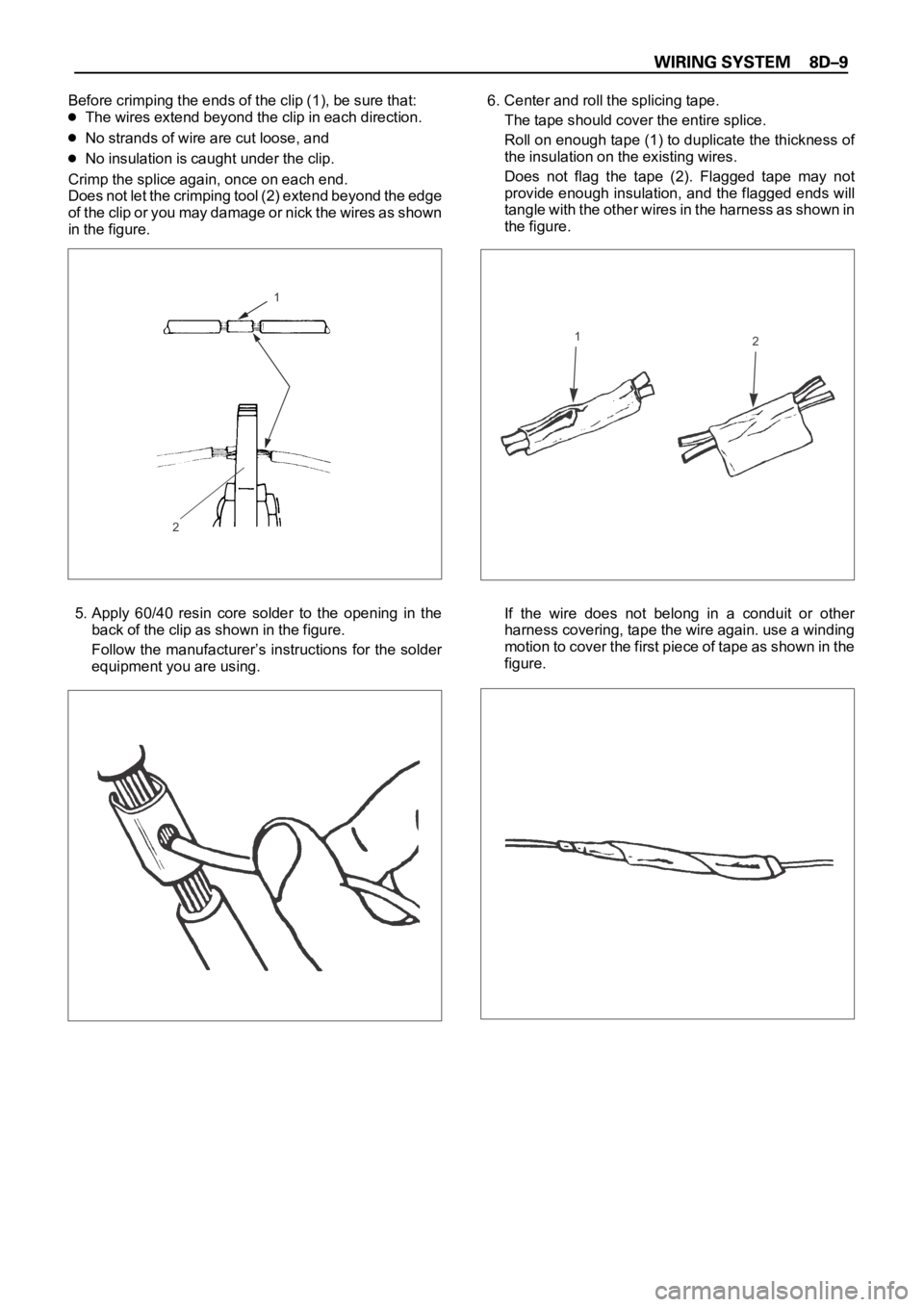
Before crimping the ends of the clip (1), be sure that:
The wires extend beyond the clip in each direction.
No strands of wire are cut loose, and
No insulation is caught under the clip.
Crimp the splice again, once on each end.
Does not let the crimping tool (2) extend beyond the edge
of the clip or you may damage or nick the wires as shown
in the figure.
5. Apply 60/40 resin core solder to the opening in the
back of the clip as shown in the figure.
Follow the manufacturer’s instructions for the solder
equipment you are using.6. Center and roll the splicing tape.
The tape should cover the entire splice.
Roll on enough tape (1) to duplicate the thickness of
the insulation on the existing wires.
Does not flag the tape (2). Flagged tape may not
provide enough insulation, and the flagged ends will
tangle with the other wires in the harness as shown in
the figure.
If the wire does not belong in a conduit or other
harness covering, tape the wire again. use a winding
motion to cover the first piece of tape as shown in the
figure.
1
2
12
Page 2650 of 6000
3.0
B/Y3.0
B/Y
3.0
B/Y3.0
B/Y3.0
W/G3.0
B/R
3.0
B/R 3.0
B/Y
0.5
R/B
HAZARD
WARNING
SW
(8)PCM
MAIN
RELAY
(1)IGNITION
COILMETER STARTER
RELAY
(6)SEAT
HEATERWINDSHIELD
WIPER
MOTORRR
WIPER
MOTORHEADLIGHT
WIPER
MOTOR
AC GENERATOR
(IG) ALARM & RELAY
CONTROL UNIT C-3 10A
TURN
BACK
0.5
L/WC-4 10A
ELEC.
IGN.
0.5
L/YC-10 10A
METER
GAUGE
0.5
W/RC-1 10A
STARTER
RELAY
0.85
W/LC-5 15A
FRT WIPER
& WASHERC-6 10A
RR WIPER
& WASHERC-7 10A
H/LAMP
WIPER
FUSE BOX
1.25
B/OC-9 15A
IG COIL C-8 15A
ENGINE
0.5
L/B
0.85
B/Y
0.85
B/Y
0.5
R
0.75
B/R
SDM
(12)C-21 10A
SRS
1.25
G/RC-2 15A
SEAT
HEATER
H-631
3
H-63
��
D08RWB15
Page 2658 of 6000
3.0
B/Y3.0
B/Y
3.0
B/Y3.0
B/Y3.0
W/G3.0
B/R
3.0
B/R 3.0
B/Y
0.5
R/B
HAZARD
WARNING
SW
(8)C-3 10A
TURN
BACK
0.5
L/WC-4 10A
ELEC.
IGN.
0.5
L/Y
METER ECM
(J2-9) ALARM & RELAY��
C O NTR O L UNITC-10 10A
METER
GAUGE
0.5
W/R
STARTER
RELAY
(6)C-1 10A
STARTER
RELAY
0.85
W/L
WINDSHIELD
WIPER
MOTORC-5 15A
FRT WIPER
& WASHERC-6 10A
RR WIPER
& WASHERC-7 10A
H/LAMP
WIPER
FUSE BOX
C-8 15A
ENGINE
0.5
L/B
RR
WIPER
MOTORHEADLIGHT
WIPER
MOTOR
0.85
B/Y
0.5
R
0.75
B/R
SDM
(12)C-21 10A
SRS
1.25
G/R
SEAT
HEATERC-2 15A
SEAT
HEATER
H-631
3
H-63
��
D08RWB20
Page 2682 of 6000
3.0
B/Y
C-3 10A
TURN, BACKC-1 10A
STARTER RELAYSTARTER SW
(IG1)EHCU : ELECTRONIC HYDRAULIC CONTROL UNIT
PCM : POWERTRAIN CONTROL MODULE
P C M
H-11H-7
6M-25
3 0.85
R/B
0.75
R/B
0.75
R/L
BACKUP
LIGHT 0.5
R/B
17M-258H-117
3.0
W/GSTARTER SW
(ST)
H-10H-12
0.5
W/L
1.25
W/L
STARTER
RELAY (6)0.5
W/RM-25
M-25
5C-3
E12 0.5
L/W
0.5
L/WH-531
M-25
6C-3
E7 0.5
L/Y
0.5
L/YH-532
M-25
7C-3
F2 0.5
L/B
0.5
L/BH-533
M-25
2C-3
F3 0.5
Y/G
0.5
Y/GH-534
8
H-87
MODE SW
1 152
C-1EHCU (6)
0.5
GR
A12
C-3
CRUISE CONTROL
UNIT (5)
0.5
GR/L
F10
M-25
1.25
W/RH-104
16H-42
D08RW595
Page 2697 of 6000
3.0
B/Y
C-3 10A
TURN, BACKC-1 10A
STARTER RELAYSTARTER SW
(IG1)EHCU : ELECTRONIC HYDRAULIC CONTROL UNIT
PCM : POWERTRAIN CONTROL MODULE
P C M
H-11H-8
6M-25
3 0.85
R/B
0.75
R/B
0.75
R/L
BACKUP
LIGHT 0.5
R/B
4M-258H-117
3.0
W/GSTARTER SW
(ST)
H-10H-8
0.5
W/L
1.25
W/L
STARTER
RELAY (6)0.5
W/RM-25
M-25
5C-3
E12 0.5
L/W
0.5
L/WH-531
M-25
6C-3
E7 0.5
L/Y
0.5
L/YH-532
M-25
7C-3
F2 0.5
L/B
0.5
L/BH-533
M-25
2C-3
F3 0.5
Y/G
0.5
Y/GH-534
8
H-72
MODE SW
1 151
C-1EHCU (6)
0.5
GR
A12
C-3
CRUISE CONTROL
UNIT (5)
0.5
GR/L
F10
M-25
1.25
W/RH-104
16H-42
D08RW909
Page 2787 of 6000
I-115
B-53
B1
H-2716
H-257
B-53
2 L
H-25100.85
R/B0.85
G/O
H-1612
HAZARD
WARNING
SW
TURN SIGNAL
LIGHT SWFLASHER
UNIT
0.85
G/B0.85
G/B
0.85
G/B0.85
P/B
0.85
P/B2.0
G/O0.3
R/G 0.85
G/R
ILLUMINATION
CONTROLLER
(3) 0.85
P/B 2.0
LG/B 0.5
B
1.25
B2.0
LG/B
2.0
LG/B
2.0
LG/B2.0
B/R2.0
B/R
0.85
R/B 0.85
R/B2.0
G/O
5.0
W BATT.(+)
F-3 15A
HORN,HAZARD3.0
B/Y STARTER SW
(IG1)
C-3 10A
TURN
BACK
B-12
B-12
4
B-12
5 3
LR
A
I-11I-11I-11I-11
64 2 1
I-117I-118I-11 TAIL RELAY
(4) BACK UP
LIGHT
3
B
B-53
3 E
HORN RELAY
(2)
H-276H-2710
B-19
BODY-RH
D08RW683
Page 2791 of 6000
I-115
B-53
B1
H-204
H-202
B-53
2 L
H-25170.85
R/B0.85
G/O
H-1614
HAZARD
WARNING
SW
TURN SIGNAL
LIGHT SWFLASHER
UNIT
0.85
G/B0.85
G/B
0.85
G/B0.85
P/B
0.85
P/B2.0
G/O0.3
R/G 0.85
G/R
ILLUMINATION
CONTROLLER
(3) 0.85
P/B 2.0
LG/B 0.5
B
1.25
B2.0
LG/B
2.0
LG/B
2.0
LG/B2.0
B/R2.0
B/R
0.85
R/B 0.85
R/B2.0
G/O
5.0
W BATT.(+)
F-3 15A
HORN,HAZARD3.0
B/Y STARTER SW
(IG1)
C-3 10A
TURN
BACK
B-12
B-12
4
B-12
5 3
LR
A
I-11I-11I-11I-11
64 2 1
I-117I-118I-11 TAIL RELAY
(4) BACK UP
LIGHT
3
B
B-53
3 E
HORN RELAY
(2)
H-2519H-2520
B-19
BODY-LH
D08RW872
Page 2814 of 6000
3.0
B/Y STARTER SW
(IG1)
MODE
SW
(A/T)
HAZARD
WARN ING
SWITCH (8)0.5
R/B
0.5
R/B 0.5
R/B
0.85
R/B
0.5
R/L0.75
R/L 0.75
R/LC-3 10A
TURN,BACK
H-2517H-717
M-25
M-258
H-117
R-4 3
A
BACKUP
LIGHT SW
(6VD1 M/T)
BACKUP
LIGHT
-LHBACKUP
LIGHT
-RH
0.85
R/B
0.75
R/B
0.5
R/L
H-11
1 6
M-8
M-91
0.85
R/L
H-55
BACKUP
LIGHT SW
(4JG2)
0.5
R/B
0.85
R/B
0.5
R/L
H-5
E-43
1 6
E-421
0.5
R/L
0.85
R/L
0.5
R/L
1.25
B1.25
B 0.5
R/L
H-328
H-716
A
BODY-RR
R-133
R-13
1
R-123
1
R-12 0.75
R/B
H-116
H-117
D08RWC64