Page 2323 of 6000
MANUAL TRANSMISSION7B–5
Manual Transmission Assembly
Transmission and Associated Parts
220RW108
Legend
(1) Gear Control Lever and Knob
(2) Transfer Control Lever and Knob
(3) Front Console Assembly
(4) Grommet Assembly
(5) Transfer Protector
(6) Rear Propeller Shaft
(7) Front Propeller Shaft
(8) Exhaust Pipe
(9) Backup Lamp, 4WD Indicator, and 1–2
Indicator Switch Harness Connector
(10) Speedometer Sensor and 2WD–4WD Actuator
Harness Connector(11) Slave Cylinder Heat Protector
(12) Harness Heat Protector
(13) Slave Cylinder
(14) Dust Cover
(15) Engine Rear Mount Nut
(16) Engine Rear Mount Bolt
(17) Engine Rear Mount
(18) Third Crossmember
(19) Flywheel Under Cover
(20) Transmission Retaining Bolt
(21) Transmission Assembly with Transfer Case
Page 2325 of 6000
MANUAL TRANSMISSION7B–7
13. Disconnect the backup lamp switch, 4WD indicator
switch and 1–2 indicator switch harness connectors.
826RW023
14. Disconnect the speedometer sensor and 2WD-4WD
actuator harness connectors.
826RW024
Page 2334 of 6000

7B–16MANUAL TRANSMISSION
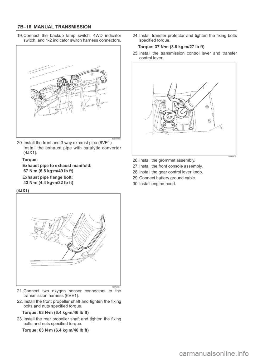
19. Connect the backup lamp switch, 4WD indicator
switch, and 1-2 indicator switch harness connectors.
826RW023
20. Install the front and 3 way exhaust pipe (6VE1).
Install the exhaust pipe with catalytic converter
(4JX1).
Torque:
Exhaust pipe to exhaust manifold:
67 Nꞏm (6.8 kgꞏm/49 Ib ft)
Exhaust pipe flange bolt:
43 Nꞏm (4.4 kgꞏm/32 Ib ft)
(4JX1)
150RW041
21. Connect two oxygen sensor connectors to the
transmission harness (6VE1).
22. Install the front propeller shaft and tighten the fixing
bolts and nuts specified torque.
Torque: 63 Nꞏm (6.4 kgꞏm/46 Ib ft)
23. Install the rear propeller shaft and tighten the fixing
bolts and nuts specified torque.
Torque: 63 Nꞏm (6.4 kgꞏm/46 Ib ft)24. Install transfer protector and tighten the fixing bolts
specified torque.
Torque: 37 Nꞏm (3.8 kgꞏm/27 Ib ft)
25. Install the transmission control lever and transfer
control lever.
235RW014
26. Install the grommet assembly.
27. Install the front console assembly.
28. Install the gear control lever knob.
29. Connect battery ground cable.
30. Install engine hood.
Page 2338 of 6000
7B–20MANUAL TRANSMISSION
220RW095
Legend
(1) Release Bearing and Shift Fork
(2) Clutch Housing
(3) Front Cover
(4) Snap Ring
(5) Snap Ring
(6) 1st and 2nd Switch
(7) Drain Plug
(8) Backup Light Switch
(9) Transmission Case(10) Filler Plug
(11) Gear Control Rod
(12) Reverse Restrict Pin
(13) Oil Receiver Pipe
(14) Transfer Adapter
(15) Plug (6VE1) or Neutral Switch (4JX1)
(16) Gear Control Box
(17) Shift Lever Housing
(18) Oil Seal
(19) Plug
Page 2339 of 6000
MANUAL TRANSMISSION7B–21
Disassembly
1. Remove the drain plug and filler plug.
1. Remove the drain plug (1) and gasket.
2. Remove the filler plug (2) and gasket.
(6VE1)
220RW007
2. Remove the clutch release bearing and shift fork.
1. Remove the clutch release bearing (3) from the
front cover.
2. Remove the split pin (4). Remove the shaft from
the under. Remove the shift fork (5).
220RW086
3. Remove the switch.
1. Remove backup light switch (6) and gasket.
2. Remove neutral switch (7) and gasket (4JX1).
3. Remove 1st and 2nd switch (8) and gasket.
(4JX1)
220RW093
4. Remove the clutch housing.
1. Remove the 9 bolts.
241RW001
Page 2360 of 6000
7B–42MANUAL TRANSMISSION
5. Using a thickness gauge, measure the clearance
between the 4th block ring back and gear spline
end.
Standard: 0.75 – 1.65 mm (0.030 – 0.065 in)
226RW064
6. Check the braking effect of the block ring. Turn
the block ring in one direction while pushing it to
the gear cone. Check that the ring locks. If it does
not lock, replace the block ring.
226RW060
7. Install the needle roller bearing.
2. Reassemble the mainshaft assembly.
NOTE: Apply all parts with engine oil before installing
them.3. Inspect block ring
1. Using a thickness gauge, measure the clearance
between the synchronizer ring back and gear
spline end.
Gear
Standard Clearanse
1st0.80–1.60mm (0.032–0.063in)
2nd0.65–1.75mm (0.026–0.069in)
3rd0.75–1.65mm (0.030–0.065in)
226RW105
2. Turn the synchronizer ring in one direction while
pushing it to the gear cone. Check that the ring
locks.
226RW106
Page 2384 of 6000

7B–66MANUAL TRANSMISSION
38. Install clutch housing.
1. Install the clutch housing to the transmission
case.
Torque: 36 Nꞏm (3.7 kgꞏm/27 lb ft)
NOTE: Tighten the all bolts evenly.
241RW001
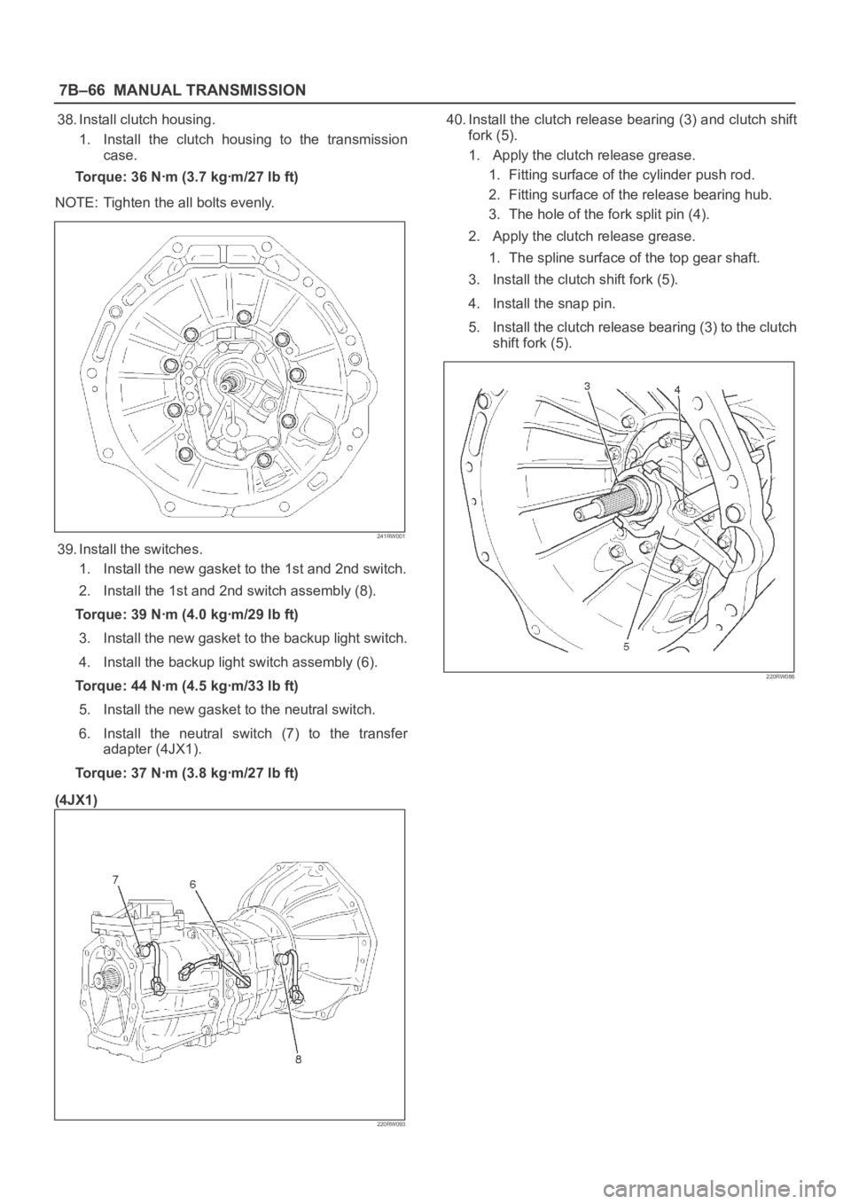
39. Install the switches.
1. Install the new gasket to the 1st and 2nd switch.
2. Install the 1st and 2nd switch assembly (8).
Torque: 39 Nꞏm (4.0 kgꞏm/29 lb ft)
3. Install the new gasket to the backup light switch.
4. Install the backup light switch assembly (6).
Torque: 44 Nꞏm (4.5 kgꞏm/33 lb ft)
5. Install the new gasket to the neutral switch.
6. Install the neutral switch (7) to the transfer
adapter (4JX1).
Torque: 37 Nꞏm (3.8 kgꞏm/27 lb ft)
(4JX1)
220RW093
40. Install the clutch release bearing (3) and clutch shift
fork (5).
1. Apply the clutch release grease.
1. Fitting surface of the cylinder push rod.
2. Fitting surface of the release bearing hub.
3. The hole of the fork split pin (4).
2. Apply the clutch release grease.
1. The spline surface of the top gear shaft.
3. Install the clutch shift fork (5).
4. Install the snap pin.
5. Install the clutch release bearing (3) to the clutch
shift fork (5).
220RW086
Page 2529 of 6000

7C–20CLUTCH
2. Adjust clutch padel adjusting bolt by backing it out
half a turn, and measure the clearance (
)
between the clutch pedal arm and the adjusting
bolt.
203RW010
Legend
(9) Bracket
(10) Clutch Pedal Adjusting Bolt
(11) Lock Nut
(12) Clutch Pedal Arm
3. Lock the lock nut.
Clutch Switch and Clutch Pedal Clearance (
)
0.5 mm – 1.5 mm (0.020 in – 0.059 in)
5. After adjusting the clutch pedal height, push the
clutch pedal by hand rightly to check the clutch pedal
free play (4) to within specification.
Pedal Free Play (4)
5 mm – 15 mm (0.20 in – 0.59 in)
203RW004
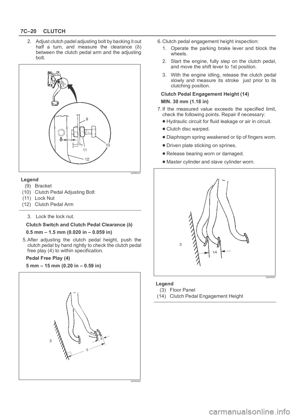
6. Clutch pedal engagement height inspection:
1. Operate the parking brake lever and block the
wheels.
2. Start the engine, fully step on the clutch pedal,
and move the shift lever to 1st position.
3. With the engine idling, release the clutch pedal
slowly and measure its stroke just prior to its
clutching position.
Clutch Pedal Engagement Height (14)
MIN. 30 mm (1.18 in)
7. If the measured value exceeds the specified limit,
check the following points. Repair if necessary:
Hydraulic circuit for fluid leakage or air in circuit.
Clutch disc warped.
Diaphragm spring weakened or tip of fingers worn.
Driven plate sticking on sprines.
Release bearing worn or damaged.
Master cylinder and slave cylinder worn.
203RW007
Legend
(3) Floor Panel
(14) Clutch Pedal Engagement Height