1998 OPEL FRONTERA transmission oil
[x] Cancel search: transmission oilPage 1805 of 6000

6A – 72 ENGINE MECHANICAL
CRANK CASE
REMOVAL
1. Drain engine oil.
2. Remove transmission assembly.
3. Remove crankshaft damper pulley.
4. Remove timing belt cover, timing belt, pulley and
front plate.
5. Remove timing gear case cover.
6. Remove timing gears.
NOTE: Do not forget to set lock bolt for idle gear A and
lock pin for idle gear C.
7. Remove timing gear case.
8. Remove oil level gauge guide assembly.
9. Remove flywheel assembly.
CAUTION:
1) The flywheel heavy; be careful not to drop it.
2) Be careful no to let it slip because the hexagon
of the bolt is thin.10. Remove rear plate (for A/T) or flywheel housing (for
MT).
11. Remove retainer.
NOTE:
1) Be careful not to damage the oil seal; it can be
reused.
2) Inspect installation portion for distortion and flow on
the slinger; also inspect for flow on the oil seal lip.
3) If there is some flow oil seal/slinger, replace a set.
12. Remove bolts from thrust plate of balance shaft LH
then remove balance shaft.
13. Loosen crank case fixing bolts.
14. Use seal cutter to take off the liquid gasket.
Seal cutter: 5-8840-2153-0
15. Remove crank case assembly.
CAUTION:
Do not give shock to crank case for prevention take
off applied vibration insulation material on the
crank case.
1
2
3
012RW029
Legend
(1) Crank Case
(2) Oil Pan
(3) Drain Plug
Page 1898 of 6000
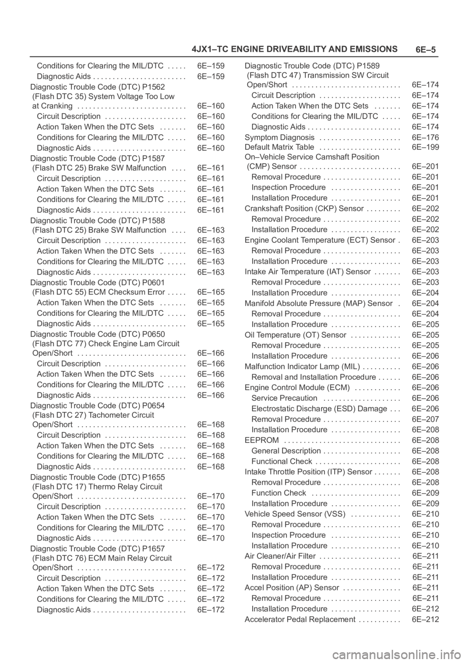
6E–5 4JX1–TC ENGINE DRIVEABILITY AND EMISSIONS
Conditions for Clearing the MIL/DTC 6E–159. . . . .
Diagnostic Aids 6E–159. . . . . . . . . . . . . . . . . . . . . . . .
Diagnostic Trouble Code (DTC) P1562
(Flash DTC 35) System Voltage Too Low
at Cranking 6E–160. . . . . . . . . . . . . . . . . . . . . . . . . . . .
Circuit Description 6E–160. . . . . . . . . . . . . . . . . . . . .
Action Taken When the DTC Sets 6E–160. . . . . . .
Conditions for Clearing the MIL/DTC 6E–160. . . . .
Diagnostic Aids 6E–160. . . . . . . . . . . . . . . . . . . . . . . .
Diagnostic Trouble Code (DTC) P1587
(Flash DTC 25) Brake SW Malfunction 6E–161. . . .
Circuit Description 6E–161. . . . . . . . . . . . . . . . . . . . .
Action Taken When the DTC Sets 6E–161. . . . . . .
Conditions for Clearing the MIL/DTC 6E–161. . . . .
Diagnostic Aids 6E–161. . . . . . . . . . . . . . . . . . . . . . . .
Diagnostic Trouble Code (DTC) P1588
(Flash DTC 25) Brake SW Malfunction 6E–163. . . .
Circuit Description 6E–163. . . . . . . . . . . . . . . . . . . . .
Action Taken When the DTC Sets 6E–163. . . . . . .
Conditions for Clearing the MIL/DTC 6E–163. . . . .
Diagnostic Aids 6E–163. . . . . . . . . . . . . . . . . . . . . . . .
Diagnostic Trouble Code (DTC) P0601
(Flash DTC 55) ECM Checksum Error 6E–165. . . . .
Action Taken When the DTC Sets 6E–165. . . . . . .
Conditions for Clearing the MIL/DTC 6E–165. . . . .
Diagnostic Aids 6E–165. . . . . . . . . . . . . . . . . . . . . . . .
Diagnostic Trouble Code (DTC) P0650
(Flash DTC 77) Check Engine Lam Circuit
Open/Short 6E–166. . . . . . . . . . . . . . . . . . . . . . . . . . . .
Circuit Description 6E–166. . . . . . . . . . . . . . . . . . . . .
Action Taken When the DTC Sets 6E–166. . . . . . .
Conditions for Clearing the MIL/DTC 6E–166. . . . .
Diagnostic Aids 6E–166. . . . . . . . . . . . . . . . . . . . . . . .
Diagnostic Trouble Code (DTC) P0654
(Flash DTC 27) Tachometer Circuit
Open/Short 6E–168. . . . . . . . . . . . . . . . . . . . . . . . . . . .
Circuit Description 6E–168. . . . . . . . . . . . . . . . . . . . .
Action Taken When the DTC Sets 6E–168. . . . . . .
Conditions for Clearing the MIL/DTC 6E–168. . . . .
Diagnostic Aids 6E–168. . . . . . . . . . . . . . . . . . . . . . . .
Diagnostic Trouble Code (DTC) P1655
(Flash DTC 17) Thermo Relay Circuit
Open/Short 6E–170. . . . . . . . . . . . . . . . . . . . . . . . . . . .
Circuit Description 6E–170. . . . . . . . . . . . . . . . . . . . .
Action Taken When the DTC Sets 6E–170. . . . . . .
Conditions for Clearing the MIL/DTC 6E–170. . . . .
Diagnostic Aids 6E–170. . . . . . . . . . . . . . . . . . . . . . . .
Diagnostic Trouble Code (DTC) P1657
(Flash DTC 76) ECM Main Relay Circuit
Open/Short 6E–172. . . . . . . . . . . . . . . . . . . . . . . . . . . .
Circuit Description 6E–172. . . . . . . . . . . . . . . . . . . . .
Action Taken When the DTC Sets 6E–172. . . . . . .
Conditions for Clearing the MIL/DTC 6E–172. . . . .
Diagnostic Aids 6E–172. . . . . . . . . . . . . . . . . . . . . . . . Diagnostic Trouble Code (DTC) P1589
(Flash DTC 47) Transmission SW Circuit
Open/Short 6E–174. . . . . . . . . . . . . . . . . . . . . . . . . . . .
Circuit Description 6E–174. . . . . . . . . . . . . . . . . . . . .
Action Taken When the DTC Sets 6E–174. . . . . . .
Conditions for Clearing the MIL/DTC 6E–174. . . . .
Diagnostic Aids 6E–174. . . . . . . . . . . . . . . . . . . . . . . .
Symptom Diagnosis 6E–176. . . . . . . . . . . . . . . . . . . . .
Default Matrix Table 6E–199. . . . . . . . . . . . . . . . . . . . .
On–Vehicle Service Camshaft Position
(CMP) Sensor 6E–201. . . . . . . . . . . . . . . . . . . . . . . . . .
Removal Procedure 6E–201. . . . . . . . . . . . . . . . . . . .
Inspection Procedure 6E–201. . . . . . . . . . . . . . . . . .
Installation Procedure 6E–201. . . . . . . . . . . . . . . . . .
Crankshaft Position (CKP) Sensor 6E–202. . . . . . . . .
Removal Procedure 6E–202. . . . . . . . . . . . . . . . . . . .
Installation Procedure 6E–202. . . . . . . . . . . . . . . . . .
Engine Coolant Temperature (ECT) Sensor 6E–203.
Removal Procedure 6E–203. . . . . . . . . . . . . . . . . . . .
Installation Procedure 6E–203. . . . . . . . . . . . . . . . . .
Intake Air Temperature (IAT) Sensor 6E–203. . . . . . .
Removal Procedure 6E–203. . . . . . . . . . . . . . . . . . . .
Installation Procedure 6E–204. . . . . . . . . . . . . . . . . .
Manifold Absolute Pressure (MAP) Sensor 6E–204.
Removal Procedure 6E–204. . . . . . . . . . . . . . . . . . . .
Installation Procedure 6E–205. . . . . . . . . . . . . . . . . .
Oil Temperature (OT) Sensor 6E–205. . . . . . . . . . . . .
Removal Procedure 6E–205. . . . . . . . . . . . . . . . . . . .
Installation Procedure 6E–206. . . . . . . . . . . . . . . . . .
Malfunction Indicator Lamp (MIL) 6E–206. . . . . . . . . .
Removal and Installation Procedure 6E–206. . . . . .
Engine Control Module (ECM) 6E–206. . . . . . . . . . . .
Service Precaution 6E–206. . . . . . . . . . . . . . . . . . . .
Electrostatic Discharge (ESD) Damage 6E–206. . .
Removal Procedure 6E–207. . . . . . . . . . . . . . . . . . . .
Installation Procedure 6E–208. . . . . . . . . . . . . . . . . .
EEPROM 6E–208. . . . . . . . . . . . . . . . . . . . . . . . . . . . . .
General Description 6E–208. . . . . . . . . . . . . . . . . . . .
Functional Check 6E–208. . . . . . . . . . . . . . . . . . . . . .
Intake Throttle Position (ITP) Sensor 6E–208. . . . . . .
Removal Procedure 6E–208. . . . . . . . . . . . . . . . . . . .
Function Check 6E–209. . . . . . . . . . . . . . . . . . . . . . .
Installation Procedure 6E–209. . . . . . . . . . . . . . . . . .
Vehicle Speed Sensor (VSS) 6E–210. . . . . . . . . . . . .
Removal Procedure 6E–210. . . . . . . . . . . . . . . . . . . .
Inspection Procedure 6E–210. . . . . . . . . . . . . . . . . .
Installation Procedure 6E–210. . . . . . . . . . . . . . . . . .
Air Cleaner/Air Filter 6E–211. . . . . . . . . . . . . . . . . . . . .
Removal Procedure 6E–211. . . . . . . . . . . . . . . . . . . .
Installation Procedure 6E–211. . . . . . . . . . . . . . . . . .
Accel Position (AP) Sensor 6E–211. . . . . . . . . . . . . . .
Removal Procedure 6E–211. . . . . . . . . . . . . . . . . . . .
Installation Procedure 6E–212. . . . . . . . . . . . . . . . . .
Accelerator Pedal Replacement 6E–212. . . . . . . . . . .
Page 1916 of 6000
6E–23 4JX1–TC ENGINE DRIVEABILITY AND EMISSIONS
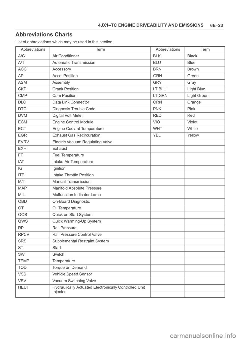
Abbreviations Charts
List of abbreviations which may be used in this section.
Abbreviations
Te r mAbbreviationsTe r m
A/CAir ConditionerBLKBlack
A/TAutomatic TransmissionBLUBlue
ACCAccessoryBRNBrown
APAccel PositionGRNGreen
ASMAssemblyGRYGray
CKPCrank PositionLT B L ULight Blue
CMPCam PositionLT G R NLight Green
DLCData Link ConnectorORNOrange
DTCDiagnosis Trouble CodePNKPink
DVMDigital Volt MeterREDRed
ECMEngine Control ModuleVIOViolet
ECTEngine Coolant TemperatureWHTWhite
EGRExhaust Gas RecircurationYELYe l l o w
EVRVElectric Vacuum Regulating Valve
EXHExhaust
FTFuel Temperature
IATIntake Air Temperature
IGIgnition
ITPIntake Throttle Position
M/TManual Transmission
MAPManifold Absolute Pressure
MILMulfunction Indicator Lamp
OBDOn-Board Diagnostic
OTOil Temperature
QOSQuick on Start System
QWSQuick Warming-Up System
RPRail Pressure
RPCVRail Pressure Control Valve
SRSSupplemental Restraint System
STStart
SWSwitch
TEMPTemperature
TODTorque on Demand
VSSVehicle Speed Sensor
VSVVacuum Switching Valve
HEUIHydraulically Actuated Electronically Controlled Unit
InjectorInjector
Page 1919 of 6000
6E–26
4JX1–TC ENGINE DRIVEABILITY AND EMISSIONS
Output Components:
Output components are diagnosed for proper response to
control module commands. Components where
functional monitoring is not feasible will be monitored for
circuit continuity and out-of-range values if applicable.
Output components to be monitored include, but are not
limited to, the following circuit:
EGR VSV
EGR EVRV
Electronic Transmission controls
Injector
Intake throttle
Glow plug
MIL control
Refer to ECM and Sensors in General Descriptions.
Passive and Active Diagnostic Tests
A passive test is a diagnostic test which simply monitors a
vehicle system or component. Conversely, an active test,
actually takes some sort of action when performing
diagnostic functions, often in response to a failed passive
test.
Intrusive Diagnostic Tests
This is any on-board test run by the Diagnostic
Management System which may have an effect on
vehicle performance or emission levels.
Warm-Up Cycle
A warm-up cycle means that engine at temperature must
reach a minimum of 70
C (160F) and rise at least 22C
(40
F) over the course of a trip.
Freeze Frame
Freeze Frame is an element of the Diagnostic
Management System which stores various vehicle
information at the moment an emissions-related fault is
stored in memory and when the MIL is commanded on.
These data can help to identify the cause of a fault. Refer
to
Storing And Erasing Freeze Fame Data for more
detailed information.
Failure Records
Failure Records data is an enhancement of the OBD
Freeze Frame feature. Failure Records store the same
vehicle information as does Freeze Frame, but it will store
that information for any fault which is stored in on-board
memory, while Freeze Frame stores information only for
emission-related faults that command the MIL on.
Common OBD Terms
Diagnostic
When used as a noun, the word diagnostic refers to any
on-board test run by the vehicle’s Diagnostic
Management System. A diagnostic is simply a test run on
a system or component to determine if the system or
component is operating according to specification. There
are many diagnostics, shown in the following list:
EGR
engine speed
vehicle speed
ECT
MAP
VSV
IAT
ITP
AP
FT (Fuel Temp)
RP (Rail Pressure)
OT (Oil Temp)
EGR EVRV
Idle SW
Brake SW
The Diagnostic Executive
The Diagnostic Executive is a unique segment of
software which is designed to coordinate and prioritize
the diagnostic procedures as well as define the protocol
for recording and displaying their results. The main
responsibilities of the Diagnostic Executive are listed as
follows:
Commanding the MIL (“Check Engine” lamp) on and
off
DTC logging and clearing
Freeze Frame data for the first emission related DTC
recorded
Current status information on each diagnostic
Diagnostic Information
The diagnostic charts and functional checks are designed
to locate a faulty circuit or component through a process
of logical decisions. The charts are prepared with the
requirement that the vehicle functioned correctly at the
time of assembly and that there are not multiple faults
present.
There is a continuous self-diagnosis on certain control
functions. This diagnostic capability is complemented by
the diagnostic procedures contained in this manual. The
language of communicating the source of the malfunction
is a system of diagnostic trouble codes. When a
malfunction is detected by the control module, a
diagnostic trouble code is set and the Malfunction
Indicator Lamp (MIL) (“Check Engine” lamp) is
illuminated.
Malfunction Indicator Lamp (MIL)
The Malfunction Indicator Lamp (MIL) looks the same as
the MIL you are already familiar with “Check Engine”
lamp.
Basically, the MIL is turned on when the ECM detects a
DTC that will impact the vehicle emissions.
When the MIL remains “ON” while the engine is
running, or when a malfunction is suspected due to a
driveability or emissions problem, a Powertrain
On-Board Diagnostic (OBD) System Check must be
performed. The procedures for these checks are
given in On-Board Diagnostic (OBD) System Check.
These checks will expose faults which may not be
detected if other diagnostics are performed first.
DTC Types
Characteristic of Code
Page 1932 of 6000
6E–39 4JX1–TC ENGINE DRIVEABILITY AND EMISSIONS
Engine Control Module ECM
Diagnosis
To read and clear diagnostic trouble codes, use a Tech 2.
IMPORTANT:Use of a Tech 2 is recommended to clear
diagnostic trouble codes from the ECM memory.
Diagnostic trouble codes can also be cleared by turning
the ignition “OFF” and disconnecting the battery power
from the ECM for 30 seconds. Turning off the ignition and
disconnecting the battery power from the ECM will cause
all diagnostic information in the ECM memory to be
cleared. Therefore, all the diagnostic tests will have to be
re-run.
Since the ECM can have a failure which may affect only
one circuit, following the diagnostic procedures in this
section will determine which circuit has a problem and
where it is.
If a diagnostic chart indicates that the ECM connections
or the ECM is the cause of a problem, and the ECM is
replaced, but this does not correct the problem, one of the
following may be the reason:
There is a problem with the ECM terminal
connections. The terminals may have to be removed
from the connector in order to check them properly.
The problem is intermittent. This means that the
problem is not present at the time the system is being
checked. In this case, refer to the
Symptoms portion
of the manual and make a careful physical inspection
of all components and wiring associated with the
affected system.
There is a shorted solenoid, relay coil, or harness.
Solenoids and relays are turned “ON” and “OFF” by
the ECM using internal electronic switches called
drivers. A shorted solenoid, relay coil, or harness will
not damage the ECM but will cause the solenoid or
relay to be inoperative.
Multiple ECM Information Sensor
DTCS Set
Circuit Description
The Engine Control Module ECM monitors various
sensors to determine the engine operating conditions.
The ECM controls fuel delivery, spark advance,
transmission operation, and emission control device
operation based on the sensor inputs.
The ECM provides a sensor ground to all of the sensors.
The ECM applies 5 volts through a pull-up resistor, and
determines the status of the following sensors by
monitoring the voltage present between the 5-volt supply
and the resistor:
The fuel temperature (FT) sensor
The engine coolant temperature (ECT) sensor
The Intake air temperature (IAT) sensor
The ECM provides the following sensors with a 5-volt
reference and a sensor ground signal:
The Intake throttle position sensor
The manifold absolute pressure sensor
The rail pressure sensor
The accelerator position sensor
The oil temperature sensor
The camshaft position sensor
The crankshaft position sensor
The EGR pressure sensor
The ECM monitors the signals from these sensors in
order to determine their operating status.
Diagnostic Aids
IMPORTANT:Be sure to inspect ECM and engine
grounds for being secure and clean.
A short to voltage in one of the sensor input circuits may
cause one or more of the following DTCs to be set:
P0337
P0342
P1193
P1404
P1405
P1488
IMPORTANT:If a sensor input circuit has been shorted
to voltage, ensure that the sensor is not damaged. A
damaged sensor will continue to indicate a high or low
voltage after the affected circuit has been repaired. If the
sensor has been damaged, replace it.
An open in the sensor ground circuit between the ECM
and the splice will cause one or more of the following
DTCs to be set:
P0337
P0342
P0117
A short to ground in the 5-volt reference A or B circuit will
cause one or more of the following DTCs to be set:
P0112
P0117
P0182
P0197
An open in the 5-volt reference circuit A, between the
ECM and the splice will cause one or more of the following
DTCs to be set:
P0107
P0405
P1194
P0122
An open in the 5-volt reference circuit B, between the
ECM and the splice will cause one or more of the following
DTCs to be set:
P1485
Check for the following conditions:
Poor connection at ECM. Inspect the harness
connectors for backed-out terminals, improper
mating, broken locks, improperly formed or damage
terminals, and a poor terminal-to-wire connection.
Damaged harness. Inspect the wiring harness for
damage. If the harness is not damaged, observe an
affected sensor’s displayed value on the Tech 2 with
the ignition “ON” and the engine “OFF” while you
move the connectors and the wiring harnesses
related to the following sensors:
ECT Sensor
Page 1935 of 6000
6E–42
4JX1–TC ENGINE DRIVEABILITY AND EMISSIONS
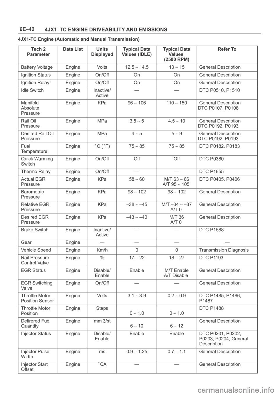
4JX1-TC Engine (Automatic and Manual Transmission)
Te c h 2
Parameter
Data ListUnits
DisplayedTy p i c a l D a t a
Values (IDLE)Typical Data
Va l u e s
(2500 RPM)Refer To
Battery VoltageEngineVo l t s12.5 14.513 15General Description
Ignition StatusEngineOn/OffOnOnGeneral Description
Ignition Relay2EngineOn/OffOnOnGeneral Description
Idle SwitchEngineInactive/
Active——DTC P0510, P1510
Manifold
Absolute
PressureEngineKPa96 106110 150General Description
DTC P0107, P0108
Rail Oil
PressureEngineMPa3.5 54.5 10General Description
DTC P0192, P0193
Desired Rail Oil
PressureEngineMPa4 55 9General Description
DTC P0192, P0193
Fuel
TemperatureEngineC (F)75 8575 85DTC P0182, P0183
Quick Warming
SwitchEngineOn/OffOffOffDTC P0380
Thermo RelayEngineOn/Off——DTC P1655
Actual EGR
PressureEngineKPa58 60M/T 63 66
A/T 95
105
DTC P0405, P0406
Barometric
PressureEngineKPa98 10298 102General Description
Relative EGR
PressureEngineKPa–38 –45M/T –34 –37
A/T 0General Description
Desired EGR
PressureEngineKPa–43 –40M/T 36
A/T 0General Description
Brake SwitchEngineInactive/
Active——DTC P1588
GearEngine————
Vehicle SpeedEngineKm/h00Transmission Diagnosis
Rail Pressure
Control ValveEngine%17 2218 27DTC P1193
EGR StatusEngineDisable/
EnableEnableM/T Enable
A/T DisableGeneral Description
EGR Switching
Va l v eEngineOn/Off——General Description
Throttle Motor
Position SensorEngineVo l t s3.1 3.90.2 0.9DTC P1485, P1486,
P1487
Throttle Motor
PositionEngineSteps
0 1.00 1.0
DTC P1488
Delirered Fuel
QuantityEnginemm 3/st
6 106 12
General Description
Injector StatusEngineDisable/
EnableEnableEnableDTC P0201, P0202,
P0203, P0204, General
Description
Injector Pulse
WidthEnginems0.9 1.250.7 1.1General Description
Injector Start
OffsetEngineCA——General Description
Page 1946 of 6000
6E–53 4JX1–TC ENGINE DRIVEABILITY AND EMISSIONS
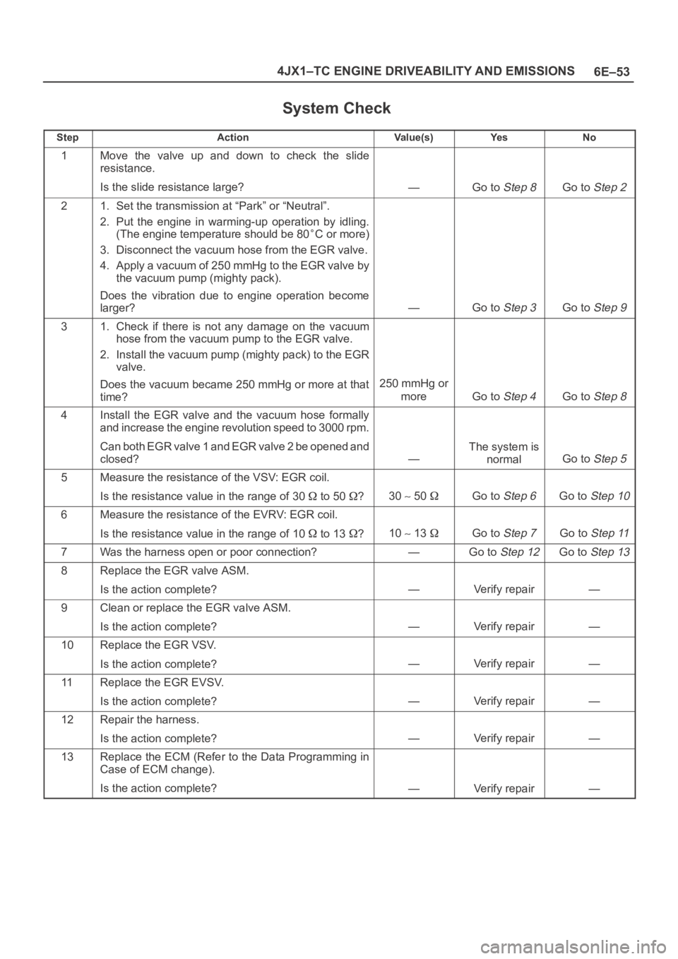
System Check
StepActionVa l u e ( s )Ye sNo
1Move the valve up and down to check the slide
resistance.
Is the slide resistance large?
—Go to Step 8Go to Step 2
21. Set the transmission at “Park” or “Neutral”.
2. Put the engine in warming-up operation by idling.
(The engine temperature should be 80
C or more)
3. Disconnect the vacuum hose from the EGR valve.
4. Apply a vacuum of 250 mmHg to the EGR valve by
the vacuum pump (mighty pack).
Does the vibration due to engine operation become
larger?
—Go to Step 3Go to Step 9
31. Check if there is not any damage on the vacuum
hose from the vacuum pump to the EGR valve.
2. Install the vacuum pump (mighty pack) to the EGR
valve.
Does the vacuum became 250 mmHg or more at that
time?
250 mmHg or
more
Go to Step 4Go to Step 8
4Install the EGR valve and the vacuum hose formally
and increase the engine revolution speed to 3000 rpm.
Can both EGR valve 1 and EGR valve 2 be opened and
closed?
—
The system is
normal
Go to Step 5
5Measure the resistance of the VSV: EGR coil.
Is the resistance value in the range of 30
to 50 ?30 50 Go to Step 6Go to Step 10
6Measure the resistance of the EVRV: EGR coil.
Is the resistance value in the range of 10
to 13 ?10 13 Go to Step 7Go to Step 11
7Was the harness open or poor connection?—Go to Step 12Go to Step 13
8Replace the EGR valve ASM.
Is the action complete?
—Verify repair—
9Clean or replace the EGR valve ASM.
Is the action complete?
—Verify repair—
10Replace the EGR VSV.
Is the action complete?
—Verify repair—
11Replace the EGR EVSV.
Is the action complete?
—Verify repair—
12Repair the harness.
Is the action complete?
—Verify repair—
13Replace the ECM (Refer to the Data Programming in
Case of ECM change).
Is the action complete?
—Verify repair—
Page 2155 of 6000
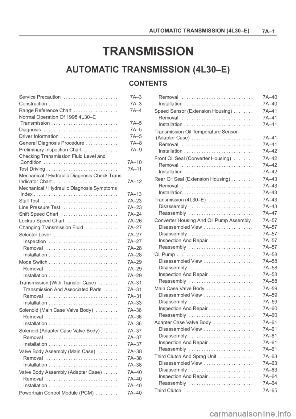
7A–1 AUTOMATIC TRANSMISSION (4L30–E)
TRANSMISSION
AUTOMATIC TRANSMISSION (4L30–E)
CONTENTS
Service Precaution 7A–3. . . . . . . . . . . . . . . . . . . . . .
Construction 7A–3. . . . . . . . . . . . . . . . . . . . . . . . . . . .
Range Reference Chart 7A–4. . . . . . . . . . . . . . . . . .
Normal Operation Of 1998 4L30–E
Transmission 7A–5. . . . . . . . . . . . . . . . . . . . . . . . . . .
Diagnosis 7A–5. . . . . . . . . . . . . . . . . . . . . . . . . . . . . .
Driver Information 7A–5. . . . . . . . . . . . . . . . . . . . . . .
General Diagnosis Procedure 7A–8. . . . . . . . . . . . .
Preliminary Inspection Chart 7A–9. . . . . . . . . . . . . .
Checking Transmission Fluid Level and
Condition 7A–10. . . . . . . . . . . . . . . . . . . . . . . . . . . . . .
Test Driving 7A–11. . . . . . . . . . . . . . . . . . . . . . . . . . . . .
Mechanical / Hydraulic Diagnosis Check Trans
Indicator Chart 7A–12. . . . . . . . . . . . . . . . . . . . . . . . . .
Mechanical / Hydraulic Diagnosis Symptoms
Index 7A–13. . . . . . . . . . . . . . . . . . . . . . . . . . . . . . . . . .
Stall Test 7A–23. . . . . . . . . . . . . . . . . . . . . . . . . . . . . . .
Line Pressure Test 7A–23. . . . . . . . . . . . . . . . . . . . . .
Shift Speed Chart 7A–24. . . . . . . . . . . . . . . . . . . . . . .
Lockup Speed Chart 7A–26. . . . . . . . . . . . . . . . . . . . .
Changing Transmission Fluid 7A–27. . . . . . . . . . . . .
Selector Lever 7A–27. . . . . . . . . . . . . . . . . . . . . . . . . .
Inspection 7A–27. . . . . . . . . . . . . . . . . . . . . . . . . . . .
Removal 7A–28. . . . . . . . . . . . . . . . . . . . . . . . . . . . .
Installation 7A–28. . . . . . . . . . . . . . . . . . . . . . . . . . . .
Mode Switch 7A–29. . . . . . . . . . . . . . . . . . . . . . . . . . . .
Removal 7A–29. . . . . . . . . . . . . . . . . . . . . . . . . . . . .
Installation 7A–29. . . . . . . . . . . . . . . . . . . . . . . . . . . .
Transmission (With Transfer Case) 7A–31. . . . . . . .
Transmission And Associated Parts 7A–31. . . . . .
Removal 7A–31. . . . . . . . . . . . . . . . . . . . . . . . . . . . .
Installation 7A–33. . . . . . . . . . . . . . . . . . . . . . . . . . . .
Solenoid (Main Case Valve Body) 7A–36. . . . . . . . .
Removal 7A–36. . . . . . . . . . . . . . . . . . . . . . . . . . . . .
Installation 7A–36. . . . . . . . . . . . . . . . . . . . . . . . . . . .
Solenoid (Adapter Case Valve Body) 7A–37. . . . . . .
Removal 7A–37. . . . . . . . . . . . . . . . . . . . . . . . . . . . .
Installation 7A–37. . . . . . . . . . . . . . . . . . . . . . . . . . . .
Valve Body Assembly (Main Case) 7A–38. . . . . . . .
Removal 7A–38. . . . . . . . . . . . . . . . . . . . . . . . . . . . .
Installation 7A–38. . . . . . . . . . . . . . . . . . . . . . . . . . . .
Valve Body Assembly (Adapter Case) 7A–40. . . . . .
Removal 7A–40. . . . . . . . . . . . . . . . . . . . . . . . . . . . .
Installation 7A–40. . . . . . . . . . . . . . . . . . . . . . . . . . . .
Powertrain Control Module (PCM) 7A–40. . . . . . . . . Removal 7A–40. . . . . . . . . . . . . . . . . . . . . . . . . . . . .
Installation 7A–40. . . . . . . . . . . . . . . . . . . . . . . . . . . .
Speed Sensor (Extension Housing) 7A–41. . . . . . . .
Removal 7A–41. . . . . . . . . . . . . . . . . . . . . . . . . . . . .
Installation 7A–41. . . . . . . . . . . . . . . . . . . . . . . . . . . .
Transmission Oil Temperature Sensor
(Adapter Case) 7A–41. . . . . . . . . . . . . . . . . . . . . . . . .
Removal 7A–41. . . . . . . . . . . . . . . . . . . . . . . . . . . . .
Installation 7A–42. . . . . . . . . . . . . . . . . . . . . . . . . . . .
Front Oil Seal (Converter Housing) 7A–42. . . . . . . .
Removal 7A–42. . . . . . . . . . . . . . . . . . . . . . . . . . . . .
Installation 7A–42. . . . . . . . . . . . . . . . . . . . . . . . . . . .
Rear Oil Seal (Extension Housing) 7A–43. . . . . . . . .
Removal 7A–43. . . . . . . . . . . . . . . . . . . . . . . . . . . . .
Installation 7A–43. . . . . . . . . . . . . . . . . . . . . . . . . . . .
Transmission (4L30–E) 7A–43. . . . . . . . . . . . . . . . . .
Disassembly 7A–43. . . . . . . . . . . . . . . . . . . . . . . . . .
Reassembly 7A–47. . . . . . . . . . . . . . . . . . . . . . . . . .
Converter Housing And Oil Pump Assembly 7A–57
Disassembled View 7A–57. . . . . . . . . . . . . . . . . . . .
Disassembly 7A–57. . . . . . . . . . . . . . . . . . . . . . . . . .
Inspection And Repair 7A–57. . . . . . . . . . . . . . . . . .
Reassembly 7A–57. . . . . . . . . . . . . . . . . . . . . . . . . .
Oil Pump 7A–58. . . . . . . . . . . . . . . . . . . . . . . . . . . . . . .
Disassembled View 7A–58. . . . . . . . . . . . . . . . . . . .
Disassembly 7A–58. . . . . . . . . . . . . . . . . . . . . . . . . .
Inspection And Repair 7A–58. . . . . . . . . . . . . . . . . .
Reassembly 7A–58. . . . . . . . . . . . . . . . . . . . . . . . . .
Main Case Valve Body 7A–59. . . . . . . . . . . . . . . . . . .
Disassembled View 7A–59. . . . . . . . . . . . . . . . . . . .
Disassembly 7A–59. . . . . . . . . . . . . . . . . . . . . . . . . .
Inspection And Repair 7A–60. . . . . . . . . . . . . . . . . .
Reassembly 7A–60. . . . . . . . . . . . . . . . . . . . . . . . . .
Adapter Case Valve Body 7A–61. . . . . . . . . . . . . . . .
Disassembled View 7A–61. . . . . . . . . . . . . . . . . . . .
Disassembly 7A–61. . . . . . . . . . . . . . . . . . . . . . . . . .
Inspection And Repair 7A–61. . . . . . . . . . . . . . . . . .
Reassembly 7A–61. . . . . . . . . . . . . . . . . . . . . . . . . .
Third Clutch And Sprag Unit 7A–63. . . . . . . . . . . . . .
Disassembled View 7A–63. . . . . . . . . . . . . . . . . . . .
Disassembly 7A–63. . . . . . . . . . . . . . . . . . . . . . . . . .
Inspection And Repair 7A–64. . . . . . . . . . . . . . . . . .
Reassembly 7A–64. . . . . . . . . . . . . . . . . . . . . . . . . .
Third Clutch 7A–65. . . . . . . . . . . . . . . . . . . . . . . . . . . .