1998 OPEL FRONTERA fuel filter
[x] Cancel search: fuel filterPage 1197 of 6000
6E–80
ENGINE DRIVEABILITY AND EMISSIONS
Circuit Description
The electronic Ignition system uses a coil-at-plug method
of spark distribution. In this type of ignition system, the
powertrain control module (PCM) triggers the correct
driver inside the ignition coil, which then triggers the
correct ignition coil based on the 58X signal received from
the crankshaft position sensor (CKP). The spark plug
connected to the coil fires when the ICM opens the ground
circuit for the coil’s primary circuit.
During crank, the PCM monitors the CKP 58X signal. The
CKP signal is used to determine which cylinder will fire
first. After the CKP 58X signal has been processed by the
PCM, it will command all six injectors to allow a priming
shot of fuel for all the cylinders. After the priming, the
injectors are left “OFF” during the next six 58X reference
pulses from the CKP. This allows each cylinder a chance
to use the fuel from the priming shot. During this waiting
period, a camshaft position (CMP) signal pulse will have
been received by the PCM. The CMP signal allows the
PCM to operate the injectors sequentially based on
camshaft position. If the camshaft position signal is not
present at start-up, the PCM will begin sequential fuel
delivery with a 1-in-6 chance that fuel delivery is correct.
The engine will run without a CMP signal, but will set a
DTC code.
Diagnostic Aids
An intermittent problem may be caused by a poor
connection, rubbed-through wire insulation or a wire
broken inside the insulation. Check for the following
items:
Poor connection or damaged harness – Inspect the
PCM harness and connectors for improper mating,
broken locks, improperly formed or damaged
terminals, poor terminal-to-wire connection, and
damaged harness.
Faulty engine coolant temperature sensor – Using
Tech 2, compare engine coolant temperature with
intake air temperature on a completely cool engine.
Engine coolant temperature should be within 10
C of
intake air temperature. If not, replace the ECT sensor.
Test Description
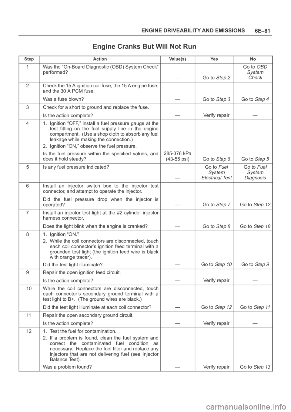
Number(s) below refer to the step number(s) on the
Diagnostic Chart.
5. An obvious cause of low fuel pressure would be an
empty fuel tank.
6. The engine will easily start and run if a few injectors
are disabled. It is not necessary to test all injectors
at this time since this step is only a test to verify that
all of the injectors have not been disabled by fuel
contamination.
7. A blinking test light verifies that the PCM is
monitoring the 58X crankshaft reference signal and
is capable of activating the injectors. If there is an
open or shorted driver circuit, DTCs 201-206 should
be set.
19.By using a spark tester, each ignition coil’s ability to
produce 25,000 volts is verified.
25.If there is an open or shorted driver circuit, DTCs
201-206 should be set. All six injector driver circuits
can be checked at one time without removing the
intake manifold if a 5-8840-2636-0 test light is
available. This is the alternative procedure:
With the ignition “OFF,” disconnect the gray
connector located at the rear of the air filter, attached
to a bracket on the purge canister.
Connect test light 5-8840-2636-0 to the connector.
Do any of the light constantly illuminate or fail to blink
when the engine is cranked? If so, repair the short or
open circuit, or replace the PCM if indicated.
This procedure only tests the driver circuit as far as the
test connection, so step 31 is added to test the circuit all
the way to the injector.
Page 1198 of 6000
6E–81 ENGINE DRIVEABILITY AND EMISSIONS
Engine Cranks But Will Not Run
StepActionVa l u e ( s )Ye sNo
1Was the “On-Board Diagnostic (OBD) System Check”
performed?
—Go to Step 2
Go to OBD
System
Check
2Check the 15 A ignition coil fuse, the 15 A engine fuse,
and the 30 A PCM fuse.
Was a fuse blown?
—Go to Step 3Go to Step 4
3Check for a short to ground and replace the fuse.
Is the action complete?
—Verify repair—
41. Ignition “OFF,” install a fuel pressure gauge at the
test fitting on the fuel supply line in the engine
compartment. (Use a shop cloth to absorb any fuel
leakage while making the connection.)
2. Ignition “ON,” observe the fuel pressure.
Is the fuel pressure within the specified values, and
does it hold steady?
285-376 kPa
(43-55 psi)
Go to Step 6Go to Step 5
5Is any fuel pressure indicated?
—
Go to Fuel
System
Electrical TestGo to Fuel
System
Diagnosis
6Install an injector switch box to the injector test
connector, and attempt to operate the injector.
Did the fuel pressure drop when the injector is
operated?
—Go to Step 7Go to Step 12
7Install an injector test light at the #2 cylinder injector
harness connector.
Does the light blink when the engine is cranked?
—Go to Step 8Go to Step 18
81. Ignition “ON.”
2. While the coil connectors are disconnected, touch
each coil connector’s ignition feed terminal with a
grounded test light (the ignition feed wire is black
with orange tracer).
Did the test light illuminate?
—Go to Step 10Go to Step 9
9Repair the open ignition feed circuit.
Is the action complete?
—Verify repair—
10While the coil connectors are disconnected, touch
each connector’s secondary ground terminal with a
test light to B+. (The ground wires are black.)
Did the test light illuminate at each coil connector?
—Go to Step 12Go to Step 11
11Repair the open secondary ground circuit.
Is the action complete?
—Verify repair—
121. Test the fuel for contamination.
2. If a problem is found, clean the fuel system and
correct the contaminated fuel condition as
necessary. Replace the fuel filter and replace any
injectors that are not delivering fuel (see Injector
Balance Test).
Was a problem found?
—Verify repairGo to Step 13
Page 1205 of 6000
6E–88
ENGINE DRIVEABILITY AND EMISSIONS
Fuel System Diagnosis
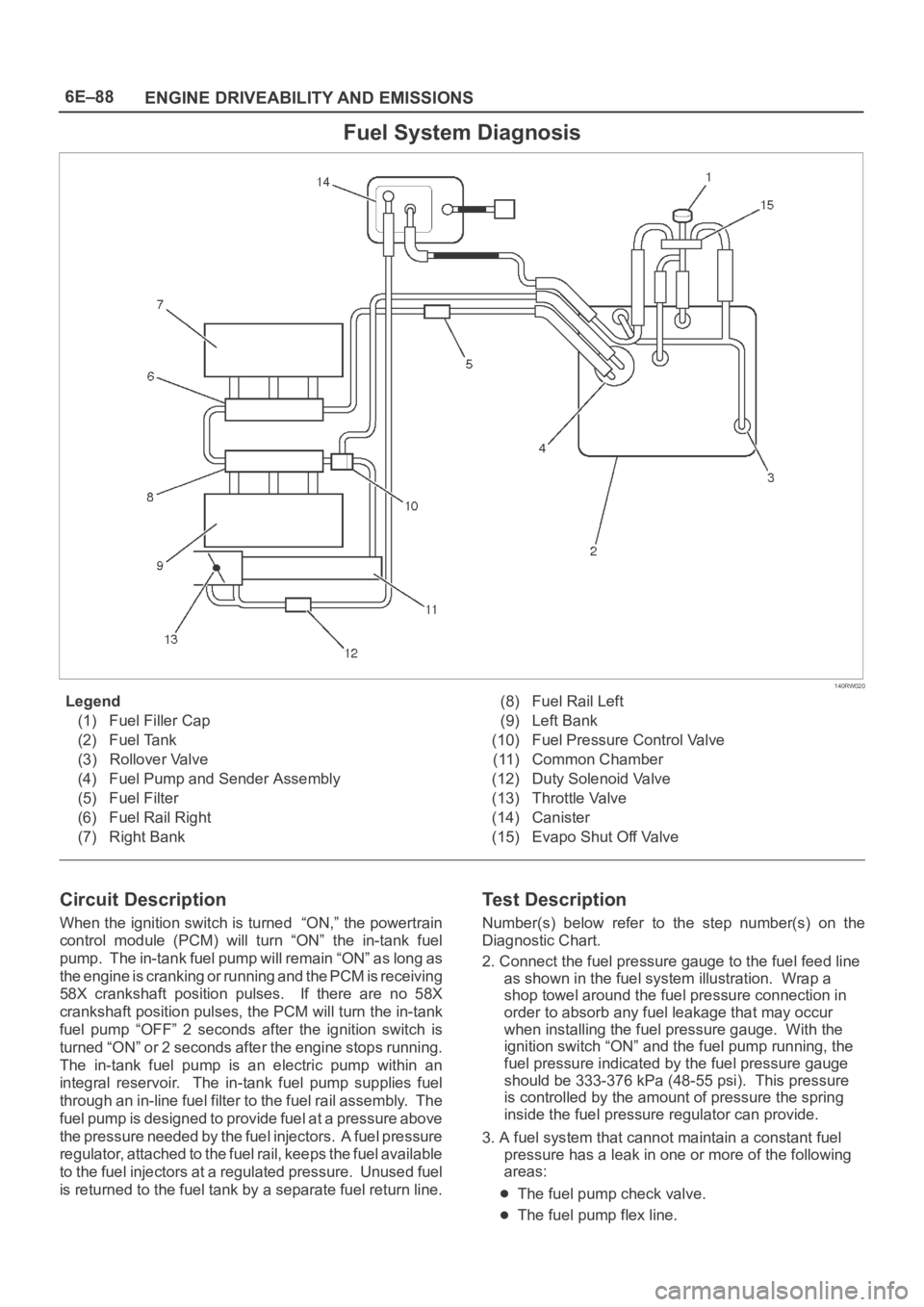
140RW020
Legend
(1) Fuel Filler Cap
(2) Fuel Tank
(3) Rollover Valve
(4) Fuel Pump and Sender Assembly
(5) Fuel Filter
(6) Fuel Rail Right
(7) Right Bank(8) Fuel Rail Left
(9) Left Bank
(10) Fuel Pressure Control Valve
(11) Common Chamber
(12) Duty Solenoid Valve
(13) Throttle Valve
(14) Canister
(15) Evapo Shut Off Valve
Circuit Description
When the ignition switch is turned “ON,” the powertrain
control module (PCM) will turn “ON” the in-tank fuel
pump. The in-tank fuel pump will remain “ON” as long as
the engine is cranking or running and the PCM is receiving
58X crankshaft position pulses. If there are no 58X
crankshaft position pulses, the PCM will turn the in-tank
fuel pump “OFF” 2 seconds after the ignition switch is
turned “ON” or 2 seconds after the engine stops running.
The in-tank fuel pump is an electric pump within an
integral reservoir. The in-tank fuel pump supplies fuel
through an in-line fuel filter to the fuel rail assembly. The
fuel pump is designed to provide fuel at a pressure above
the pressure needed by the fuel injectors. A fuel pressure
regulator, attached to the fuel rail, keeps the fuel available
to the fuel injectors at a regulated pressure. Unused fuel
is returned to the fuel tank by a separate fuel return line.
Test Description
Number(s) below refer to the step number(s) on the
Diagnostic Chart.
2. Connect the fuel pressure gauge to the fuel feed line
as shown in the fuel system illustration. Wrap a
shop towel around the fuel pressure connection in
order to absorb any fuel leakage that may occur
when installing the fuel pressure gauge. With the
ignition switch “ON” and the fuel pump running, the
fuel pressure indicated by the fuel pressure gauge
should be 333-376 kPa (48-55 psi). This pressure
is controlled by the amount of pressure the spring
inside the fuel pressure regulator can provide.
3. A fuel system that cannot maintain a constant fuel
pressure has a leak in one or more of the following
areas:
The fuel pump check valve.
The fuel pump flex line.
Page 1207 of 6000
6E–90
ENGINE DRIVEABILITY AND EMISSIONS
Fuel System Diagnosis
StepActionVa l u e ( s )Ye sNo
1Was the “On-Board Diagnostic (OBD) System Check”
performed?
—Go to Step 2
Go to OBD
System
Check
21. Turn the ignition “OFF.”
2. Turn the air conditioning system “OFF.”
3. Relieve fuel system pressure and install the fuel
pressure gauge.
4. Turn the ignition “ON.”
NOTE: The fuel pump will run for approximately 2
seconds. Use Tech 2 to command the fuel pump “ON”.
5. Observe the fuel pressure indicated by the fuel
pressure gauge with the fuel pump running.
Is the fuel pressure within the specified limits?
290-376 kPa
(42-55 psi)
Go to Step 3Go to Step 17
3NOTE: The fuel pressure will drop when the fuel pump
stops running, then it should stabilize and remain
constant.
Does the fuel pressure indicated by the fuel pressure
gauge remain constant?
—Go to Step 4Go to Step 12
41. When the vehicle is at normal operation
temperature, turn the ignition “ON” to build fuel
pressure and observe the measurement on the
gauge.
2. Start the engine and observe the fuel pressure
gauge.
Did the reading drop by the amount specified after the
engine was started?
21-105 kPa
(3-15 psi)
Go to Step 5Go to Step 9
5Is fuel pressure dropping off during acceleration,
cruise, or hard cornering?
—Go to Step 6
Check for
improper fuel
6Visually and physically inspect the following items for a
restriction:
The in-pipe fuel filter.
The fuel feed line.
Was a restriction found?
—Verify repairGo to Step 7
7Remove the fuel tank and visually and physically
inspect the following items:
The fuel pump strainer for a restriction.
The fuel line for a leak.
Verify that the correct fuel pump is in the vehicle.
Was a problem found in any of these areas?
—Verify repairGo to Step 8
8Replace the fuel pump.
Is the action complete?
—Verify repair—
91. Disconnect the vacuum hose from the fuel pressure
regulator.
2. With the engine idling, apply 12-14 inches of
vacuum to the fuel pressure regulator.
Does the fuel pressure indicated by the fuel pressure
gauge drop by the amount specified?
21-105 kPa
(3-15 psi)
Go to Step 10Go to Step 11
Page 1224 of 6000
6E–107 ENGINE DRIVEABILITY AND EMISSIONS
Diagnostic Trouble Code (DTC) P0102 MAF Sensor Circuit Low Frequency
T321122
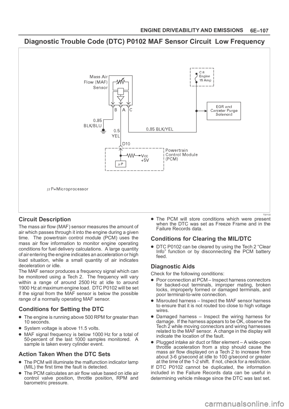
Circuit Description
The mass air flow (MAF) sensor measures the amount of
air which passes through it into the engine during a given
time. The powertrain control module (PCM) uses the
mass air flow information to monitor engine operating
conditions for fuel delivery calculations. A large quantity
of air entering the engine indicates an acceleration or high
load situation, while a small quantity of air indicates
deceleration or idle.
The MAF sensor produces a frequency signal which can
be monitored using a Tech 2. The frequency will vary
within a range of around 2500 Hz at idle to around
1900 Hz at maximum engine load. DTC P0102 will be set
if the signal from the MAF sensor is below the possible
range of a normally operating MAF sensor.
Conditions for Setting the DTC
The engine is running above 500 RPM for greater than
10 seconds.
System voltage is above 11.5 volts.
MAF signal frequency is below 1000 Hz for a total of
50-percent of the last 1000 samples monitored. A
sample is taken every cylinder event.
Action Taken When the DTC Sets
The PCM will illuminate the malfunction indicator lamp
(MIL) the first time the fault is detected.
The PCM calculates an air flow value based on idle air
control valve position, throttle position, RPM and
barometric pressure.
The PCM will store conditions which were present
when the DTC was set as Freeze Frame and in the
Failure Records data.
Conditions for Clearing the MIL/DTC
DTC P0102 can be cleared by using the Tech 2 “Clear
Info” function or by disconnecting the PCM battery
feed.
Diagnostic Aids
Check for the following conditions:
Poor connection at PCM – Inspect harness connectors
for backed-out terminals, improper mating, broken
locks, improperly formed or damaged terminals, and
poor terminal-to-wire connection.
Misrouted harness – Inspect the MAF sensor harness
to ensure that it is not routed too close to high voltage
wires.
Damaged harness – Inspect the wiring harness for
damage. If the harness appears to be OK, observe the
Tech 2 while moving connectors and wiring harnesses
related to the MAF sensor. A change in the display will
indicate the location of the fault.
Plugged intake air duct or filter element – A wide-open
throttle acceleration from a stop should cause the
mass air flow displayed on a Tech 2 to increase from
about 3-6 g/second at idle to 100 g/second or greater
at the time of the 1-2 shift. If not, check for a restriction.
If DTC P0102 cannot be duplicated, the information
included in the Failure Records data can be useful in
determining vehicle mileage since the DTC was last set.
Page 1277 of 6000
6E–160
ENGINE DRIVEABILITY AND EMISSIONS
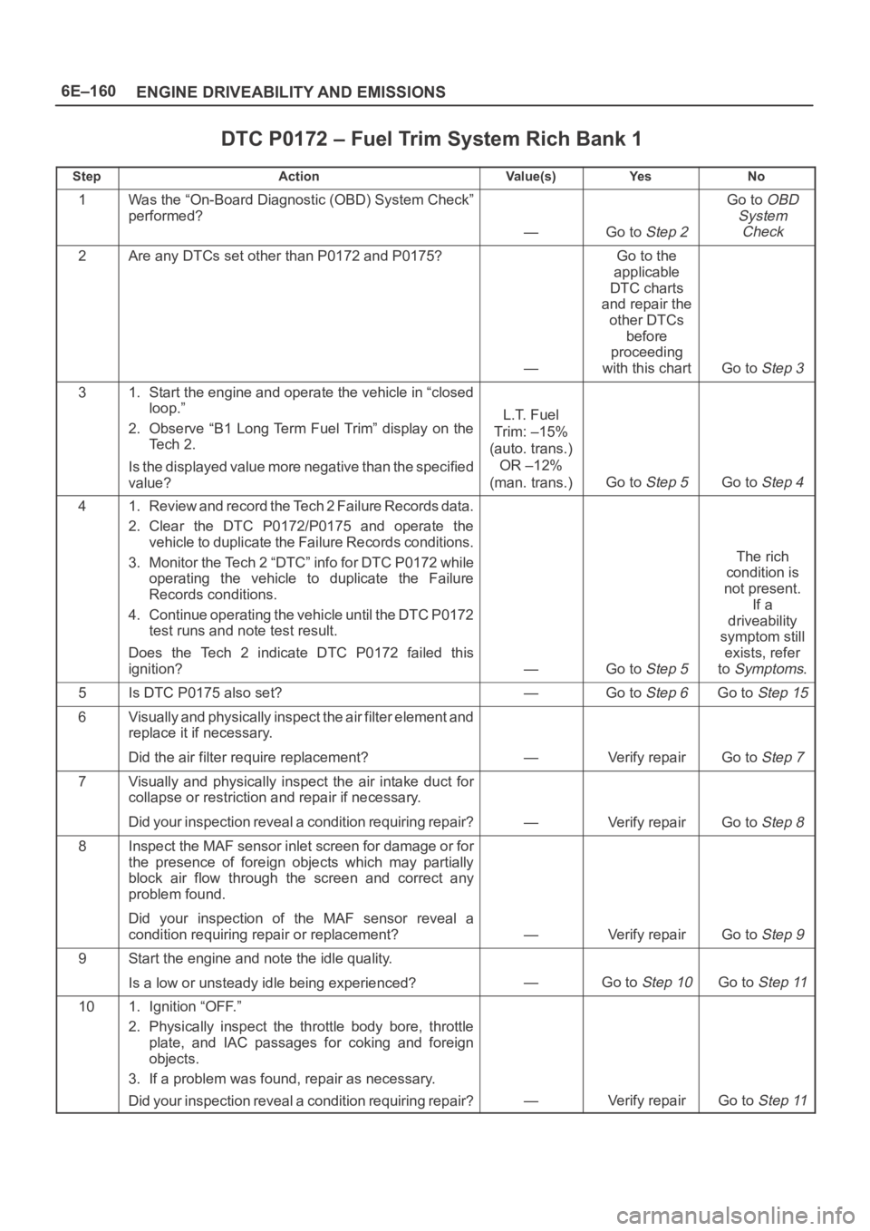
DTC P0172 – Fuel Trim System Rich Bank 1
StepActionVa l u e ( s )Ye sNo
1Was the “On-Board Diagnostic (OBD) System Check”
performed?
—Go to Step 2
Go to OBD
System
Check
2Are any DTCs set other than P0172 and P0175?
—
Go to the
applicable
DTC charts
and repair the
other DTCs
before
proceeding
with this chart
Go to Step 3
31. Start the engine and operate the vehicle in “closed
loop.”
2. Observe “B1 Long Term Fuel Trim” display on the
Te c h 2 .
Is the displayed value more negative than the specified
value?
L.T. Fuel
Trim: –15%
(auto. trans.)
OR –12%
(man. trans.)
Go to Step 5Go to Step 4
41. Review and record the Tech 2 Failure Records data.
2. Clear the DTC P0172/P0175 and operate the
vehicle to duplicate the Failure Records conditions.
3. Monitor the Tech 2 “DTC” info for DTC P0172 while
operating the vehicle to duplicate the Failure
Records conditions.
4. Continue operating the vehicle until the DTC P0172
test runs and note test result.
Does the Tech 2 indicate DTC P0172 failed this
ignition?
—Go to Step 5
The rich
condition is
not present.
If a
driveability
symptom still
exists, refer
to
Symptoms.
5Is DTC P0175 also set?—Go to Step 6Go to Step 15
6V i s u a l l y a n d p h y s i c a l l y i n s p e c t t h e a i r f i l t e r e l e m e n t a n d
replace it if necessary.
Did the air filter require replacement?
—Verify repairGo to Step 7
7Visually and physically inspect the air intake duct for
collapse or restriction and repair if necessary.
Did your inspection reveal a condition requiring repair?
—Verify repairGo to Step 8
8Inspect the MAF sensor inlet screen for damage or for
the presence of foreign objects which may partially
block air flow through the screen and correct any
problem found.
Did your inspection of the MAF sensor reveal a
condition requiring repair or replacement?
—Verify repairGo to Step 9
9Start the engine and note the idle quality.
Is a low or unsteady idle being experienced?
—Go to Step 10Go to Step 11
101. Ignition “OFF.”
2. Physically inspect the throttle body bore, throttle
plate, and IAC passages for coking and foreign
objects.
3. If a problem was found, repair as necessary.
Did your inspection reveal a condition requiring repair?
—Verify repairGo to Step 11
Page 1285 of 6000
6E–168
ENGINE DRIVEABILITY AND EMISSIONS
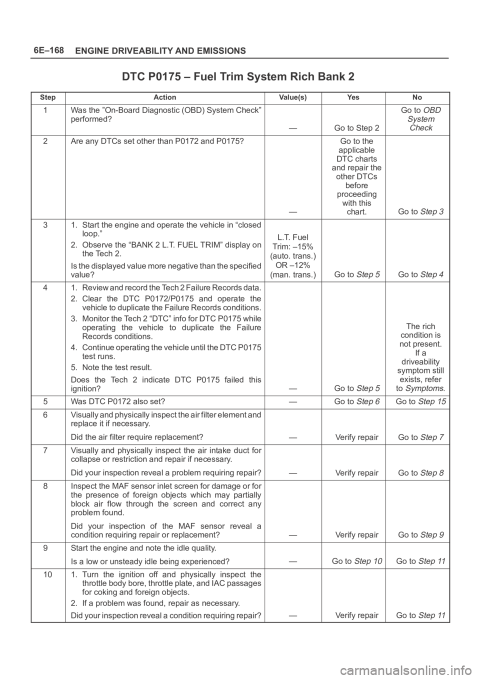
DTC P0175 – Fuel Trim System Rich Bank 2
StepActionVa l u e ( s )Ye sNo
1Was the ”On-Board Diagnostic (OBD) System Check”
performed?
—Go to Step 2
Go to OBD
System
Check
2Are any DTCs set other than P0172 and P0175?
—
Go to the
applicable
DTC charts
and repair the
other DTCs
before
proceeding
with this
chart.
Go to Step 3
31. Start the engine and operate the vehicle in “closed
loop.”
2. Observe the “BANK 2 L.T. FUEL TRIM” display on
the Tech 2.
Is the displayed value more negative than the specified
value?
L.T. Fuel
Trim: –15%
(auto. trans.)
OR –12%
(man. trans.)
Go to Step 5Go to Step 4
41. Review and record the Tech 2 Failure Records data.
2. Clear the DTC P0172/P0175 and operate the
vehicle to duplicate the Failure Records conditions.
3. Monitor the Tech 2 “DTC” info for DTC P0175 while
operating the vehicle to duplicate the Failure
Records conditions.
4. Continue operating the vehicle until the DTC P0175
test runs.
5. Note the test result.
Does the Tech 2 indicate DTC P0175 failed this
ignition?
—Go to Step 5
The rich
condition is
not present.
If a
driveability
symptom still
exists, refer
to
Symptoms.
5Was DTC P0172 also set?—Go to Step 6Go to Step 15
6V i s u a l l y a n d p h y s i c a l l y i n s p e c t t h e a i r f i l t e r e l e m e n t a n d
replace it if necessary.
Did the air filter require replacement?
—Verify repairGo to Step 7
7Visually and physically inspect the air intake duct for
collapse or restriction and repair if necessary.
Did your inspection reveal a problem requiring repair?
—Verify repairGo to Step 8
8Inspect the MAF sensor inlet screen for damage or for
the presence of foreign objects which may partially
block air flow through the screen and correct any
problem found.
Did your inspection of the MAF sensor reveal a
condition requiring repair or replacement?
—Verify repairGo to Step 9
9Start the engine and note the idle quality.
Is a low or unsteady idle being experienced?
—Go to Step 10Go to Step 11
101. Turn the ignition off and physically inspect the
throttle body bore, throttle plate, and IAC passages
for coking and foreign objects.
2. If a problem was found, repair as necessary.
Did your inspection reveal a condition requiring repair?
—Verify repairGo to Step 11
Page 1362 of 6000
6E–245 ENGINE DRIVEABILITY AND EMISSIONS
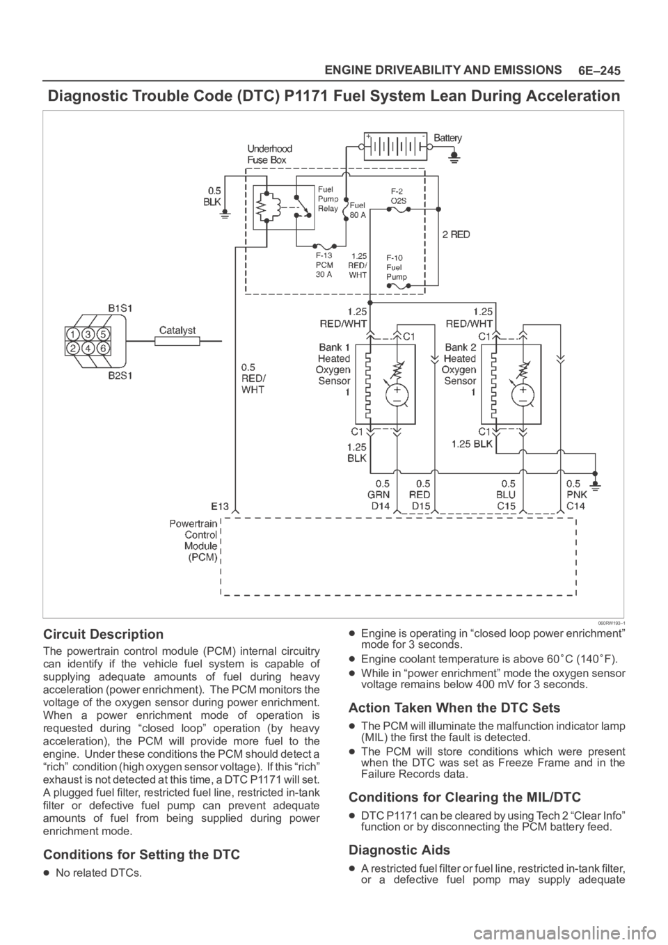
Diagnostic Trouble Code (DTC) P1171 Fuel System Lean During Acceleration
060RW193–1
Circuit Description
The powertrain control module (PCM) internal circuitry
can identify if the vehicle fuel system is capable of
supplying adequate amounts of fuel during heavy
acceleration (power enrichment). The PCM monitors the
voltage of the oxygen sensor during power enrichment.
When a power enrichment mode of operation is
requested during “closed loop” operation (by heavy
acceleration), the PCM will provide more fuel to the
engine. Under these conditions the PCM should detect a
“rich” condition (high oxygen sensor voltage). If this “rich”
exhaust is not detected at this time, a DTC P1171 will set.
A plugged fuel filter, restricted fuel line, restricted in-tank
filter or defective fuel pump can prevent adequate
amounts of fuel from being supplied during power
enrichment mode.
Conditions for Setting the DTC
No related DTCs.
Engine is operating in “closed loop power enrichment”
mode for 3 seconds.
Engine coolant temperature is above 60C (140F).
While in “power enrichment” mode the oxygen sensor
voltage remains below 400 mV for 3 seconds.
Action Taken When the DTC Sets
The PCM will illuminate the malfunction indicator lamp
(MIL) the first the fault is detected.
The PCM will store conditions which were present
when the DTC was set as Freeze Frame and in the
Failure Records data.
Conditions for Clearing the MIL/DTC
DTC P1171 can be cleared by using Tech 2 “Clear Info”
function or by disconnecting the PCM battery feed.
Diagnostic Aids
A restricted fuel filter or fuel line, restricted in-tank filter,
or a defective fuel pomp may supply adequate