1998 OPEL FRONTERA fuel filter
[x] Cancel search: fuel filterPage 1071 of 6000
6C–4
ENGINE FUEL
Fuel Filter
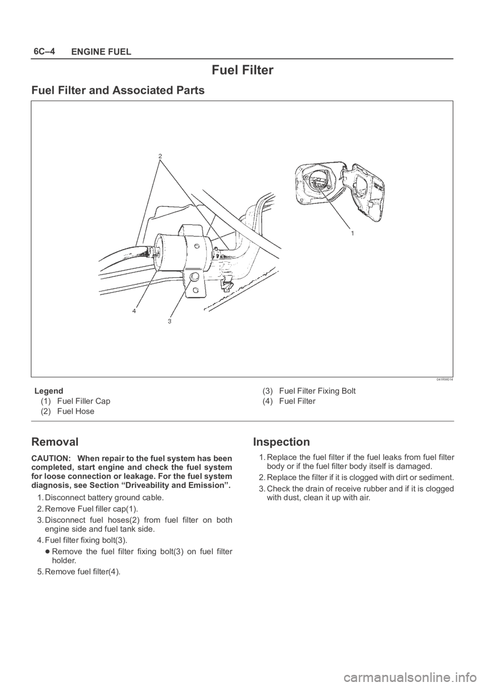
Fuel Filter and Associated Parts
041RW014
Legend
(1) Fuel Filler Cap
(2) Fuel Hose(3) Fuel Filter Fixing Bolt
(4) Fuel Filter
Removal
CAUTION: When repair to the fuel system has been
completed, start engine and check the fuel system
for loose connection or leakage. For the fuel system
diagnosis, see Section “Driveability and Emission”.
1. Disconnect battery ground cable.
2. Remove Fuel filler cap(1).
3. Disconnect fuel hoses(2) from fuel filter on both
engine side and fuel tank side.
4. Fuel filter fixing bolt(3).
Remove the fuel filter fixing bolt(3) on fuel filter
holder.
5. Remove fuel filter(4).
Inspection
1. Replace the fuel filter if the fuel leaks from fuel filter
body or if the fuel filter body itself is damaged.
2. Replace the filter if it is clogged with dirt or sediment.
3. Check the drain of receive rubber and if it is clogged
with dust, clean it up with air.
Page 1072 of 6000
6C–5
ENGINE FUEL
Installation
1. Install the fuel filter in the proper direction.
2. Install fuel filter holder fixing bolt.
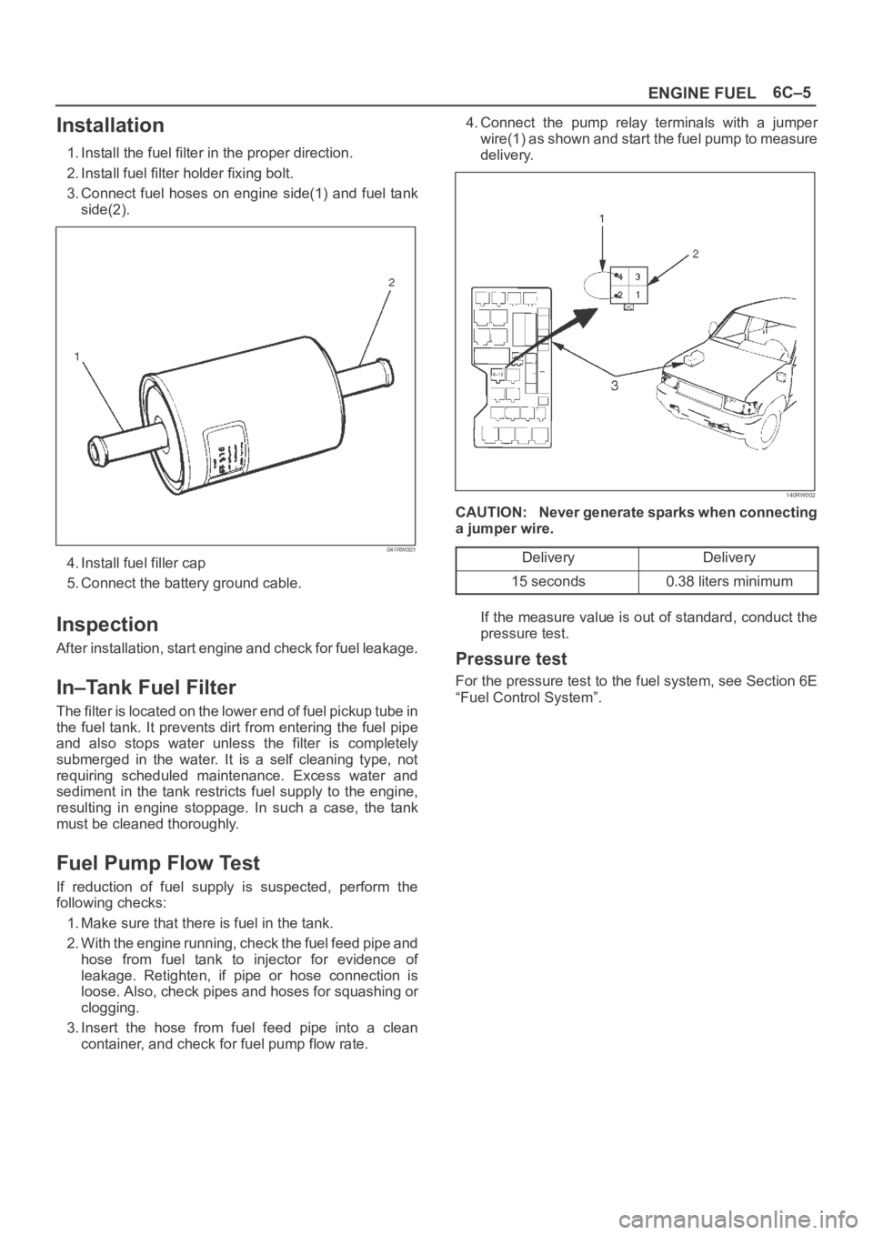
3. Connect fuel hoses on engine side(1) and fuel tank
side(2).
041RW001
4. Install fuel filler cap
5. Connect the battery ground cable.
Inspection
After installation, start engine and check for fuel leakage.
In–Tank Fuel Filter
The filter is located on the lower end of fuel pickup tube in
the fuel tank. It prevents dirt from entering the fuel pipe
and also stops water unless the filter is completely
submerged in the water. It is a self cleaning type, not
requiring scheduled maintenance. Excess water and
sediment in the tank restricts fuel supply to the engine,
resulting in engine stoppage. In such a case, the tank
must be cleaned thoroughly.
Fuel Pump Flow Test
If reduction of fuel supply is suspected, perform the
following checks:
1. Make sure that there is fuel in the tank.
2. With the engine running, check the fuel feed pipe and
hose from fuel tank to injector for evidence of
leakage. Retighten, if pipe or hose connection is
loose. Also, check pipes and hoses for squashing or
clogging.
3. Insert the hose from fuel feed pipe into a clean
container, and check for fuel pump flow rate.4. Connect the pump relay terminals with a jumper
wire(1) as shown and start the fuel pump to measure
delivery.
140RW002
CAUTION: Never generate sparks when connecting
a jumper wire.
Delivery
Delivery
15 seconds0.38 liters minimum
If the measure value is out of standard, conduct the
pressure test.
Pressure test
For the pressure test to the fuel system, see Section 6E
“Fuel Control System”.
Page 1120 of 6000
6E–3 ENGINE DRIVEABILITY AND EMISSIONS
Diagnostic Trouble Code (DTC) P0351
Ignition 1 Control Circuit 6E–206. . . . . . . . . . . . . . . . .
Diagnostic Trouble Code (DTC) P0352
Ignition 2 Control Circuit 6E–209. . . . . . . . . . . . . . . . .
Diagnostic Trouble Code (DTC) P0353
Ignition 3 Control Circuit 6E–212. . . . . . . . . . . . . . . . .
Diagnostic Trouble Code (DTC) P0354
Ignition 4 Control Circuit 6E–215. . . . . . . . . . . . . . . . .
Diagnostic Trouble Code (DTC) P0355
Ignition 5 Control Circuit 6E–218. . . . . . . . . . . . . . . . .
Diagnostic Trouble Code (DTC) P0356
Ignition 6 Control Circuit 6E–221. . . . . . . . . . . . . . . . .
Diagnostic Trouble Code (DTC) P0402
EGR Pintle Crank Error 6E–224. . . . . . . . . . . . . . . . . .
Diagnostic Trouble Code (DTC) P0404
EGR Open Stuck 6E–226. . . . . . . . . . . . . . . . . . . . . . .
Diagnostic Trouble Code (DTC) P0405
EGR Low Voltage 6E–228. . . . . . . . . . . . . . . . . . . . . . .
Diagnostic Trouble Code (DTC) P0406
EGR High Voltage 6E–231. . . . . . . . . . . . . . . . . . . . . .
Diagnostic Trouble Code (DTC) P0502
VSS Circuit Low Input 6E–234. . . . . . . . . . . . . . . . . . .
Diagnostic Trouble Code (DTC) P0562
System Voltage Low 6E–237. . . . . . . . . . . . . . . . . . . .
Diagnostic Trouble Code (DTC) P0563
System Voltage High 6E–239. . . . . . . . . . . . . . . . . . . .
Diagnostic Trouble Code (DTC) P0601
PCM Memory 6E–240. . . . . . . . . . . . . . . . . . . . . . . . . .
Diagnostic Trouble Code (DTC) P1154
HO2S Circuit Transition Time Ratio Bank 2
Sensor 1 6E–241. . . . . . . . . . . . . . . . . . . . . . . . . . . . . .
Diagnostic Trouble Code (DTC) P1171
Fuel System Lean During Acceleration 6E–245. . . .
Diagnostic Trouble Code (DTC) P1380
ABS Rough Road ABS System Fault 6E–248. . . . . .
Diagnostic Trouble Code (DTC) P1404
EGR Closed Stuck 6E–249. . . . . . . . . . . . . . . . . . . . . .
Diagnostic Trouble Code (DTC) P1508
IAC System Low RPM 6E–251. . . . . . . . . . . . . . . . . . .
Diagnostic Trouble Code (DTC) P1509
IAC System High RPM 6E–254. . . . . . . . . . . . . . . . . .
Diagnostic Trouble Code (DTC) P1618
Serial Peripheral Interface (SPI) PCM
Interprocessor Communication Error 6E–257. . . . . .
Diagnostic Trouble Code (DTC) P1625
PCM Unexpected Reset 6E–258. . . . . . . . . . . . . . . . .
Diagnostic Trouble Code (DTC) P1640
Driver-1-Input High Voltage 6E–259. . . . . . . . . . . . . .
Symptom Diagnosis 6E–262. . . . . . . . . . . . . . . . . . . . .
Default Matrix Table 6E–288. . . . . . . . . . . . . . . . . . . . .
Camshaft Position (CMP) Sensor 6E–291. . . . . . . . . .
Crankshaft Position (CKP) Sensor 6E–292. . . . . . . . .
Engine Coolant Temperature (ECT) Sensor 6E–292.
Heated Oxygen Sensor (HO2S) 6E–293. . . . . . . . . . .
Intake Air Temperature (IAT) Sensor 6E–295. . . . . . .
Knock Sensor (KS) 6E–296. . . . . . . . . . . . . . . . . . . . . . Mass Air Flow (MAF) Sensor 6E–297. . . . . . . . . . . . .
Manifold Absolute Pressure (MAP) Sensor 6E–297.
Malfunction Indicator Lamp (MIL) 6E–298. . . . . . . . . .
Powertrain Control Module (PCM) 6E–298. . . . . . . . .
EEPROM 6E–300. . . . . . . . . . . . . . . . . . . . . . . . . . . . . .
Power Steering Pressure (PSP) Switch 6E–300
. . . .
Throttle Position (TP) Sensor 6E–301. . . . . . . . . . . . .
Vehicle Speed Sensor (VSS) 6E–302. . . . . . . . . . . . .
Air Cleaner/Air Filter 6E–303. . . . . . . . . . . . . . . . . . . . .
Idle Air Control (IAC) Valve 6E–304. . . . . . . . . . . . . . .
Common Chamber 6E–305. . . . . . . . . . . . . . . . . . . . . .
Accelerator Cable Assembly 6E–305. . . . . . . . . . . . . .
Accelerator Pedal Replacement 6E–308. . . . . . . . . . .
Fuel Filter Cap 6E–310. . . . . . . . . . . . . . . . . . . . . . . . . .
Fuel Filter 6E–310. . . . . . . . . . . . . . . . . . . . . . . . . . . . . .
Fuel Gauge Unit 6E–313. . . . . . . . . . . . . . . . . . . . . . . .
Fuel Injectors 6E–314. . . . . . . . . . . . . . . . . . . . . . . . . . .
Fuel Pressure Regulator 6E–315. . . . . . . . . . . . . . . . .
Fuel Metering System 6E–317. . . . . . . . . . . . . . . . . . . .
Fuel Pump Assembly 6E–318. . . . . . . . . . . . . . . . . . . .
Fuel Pump Relay 6E–319. . . . . . . . . . . . . . . . . . . . . . . .
Fuel Rail Assembly 6E–319. . . . . . . . . . . . . . . . . . . . . .
Fuel Tank 6E–321. . . . . . . . . . . . . . . . . . . . . . . . . . . . . .
Throttle Body (TB) 6E–323. . . . . . . . . . . . . . . . . . . . . . .
Electronic Ignition System 6E–324. . . . . . . . . . . . . . . .
Catalytic Converter 6E–325. . . . . . . . . . . . . . . . . . . . . .
Air Conditioning Relay 6E–325. . . . . . . . . . . . . . . . . . .
EVAP Canister Hoses 6E–326. . . . . . . . . . . . . . . . . . . .
EVAP Canister 6E–326. . . . . . . . . . . . . . . . . . . . . . . . . .
EVAP Canister Purge Solenoid 6E–327. . . . . . . . . . . .
Fuel Tank Vent Valve 6E–328. . . . . . . . . . . . . . . . . . . .
Linear Exhaust Gas Recirculation
(EGR) Valve 6E–328. . . . . . . . . . . . . . . . . . . . . . . . . . .
Positive Crankcase Ventilation (PCV) Valve 6E–329.
Wiring and Connectors 6E–330. . . . . . . . . . . . . . . . . . .
PCM Connectors and Terminals 6E–330. . . . . . . . . . .
Wire Harness Repair: Twisted Shielded
Cable 6E–330. . . . . . . . . . . . . . . . . . . . . . . . . . . . . . . . .
Twisted Leads 6E–331. . . . . . . . . . . . . . . . . . . . . . . . . .
Weather-Pack Connector 6E–332. . . . . . . . . . . . . . . . .
Com-Pack III 6E–333. . . . . . . . . . . . . . . . . . . . . . . . . . .
Metri-Pack 6E–333. . . . . . . . . . . . . . . . . . . . . . . . . . . . .
General Description 6E–335. . . . . . . . . . . . . . . . . . . . .
General Description (PCM and Sensors) 6E–335. . .
58X Reference PCM Input 6E–335. . . . . . . . . . . . . .
A/C Request Signal 6E–335. . . . . . . . . . . . . . . . . . . .
Crankshaft Position (CKP) Sensor 6E–335. . . . . . .
Camshaft Position (CMP) Sensor and
Signal 6E–335. . . . . . . . . . . . . . . . . . . . . . . . . . . . . . .
Engine Coolant Temperature (ECT) Sensor 6E–335
Electrically Erasable Programmable Read
Only Memory (EEPROM) 6E–336. . . . . . . . . . . . . .
Fuel Control Heated Oxygen Sensors 6E–336. . . .
Intake Air Temperature (IAT) Sensor 6E–336. . . . .
Page 1146 of 6000
6E–29 ENGINE DRIVEABILITY AND EMISSIONS
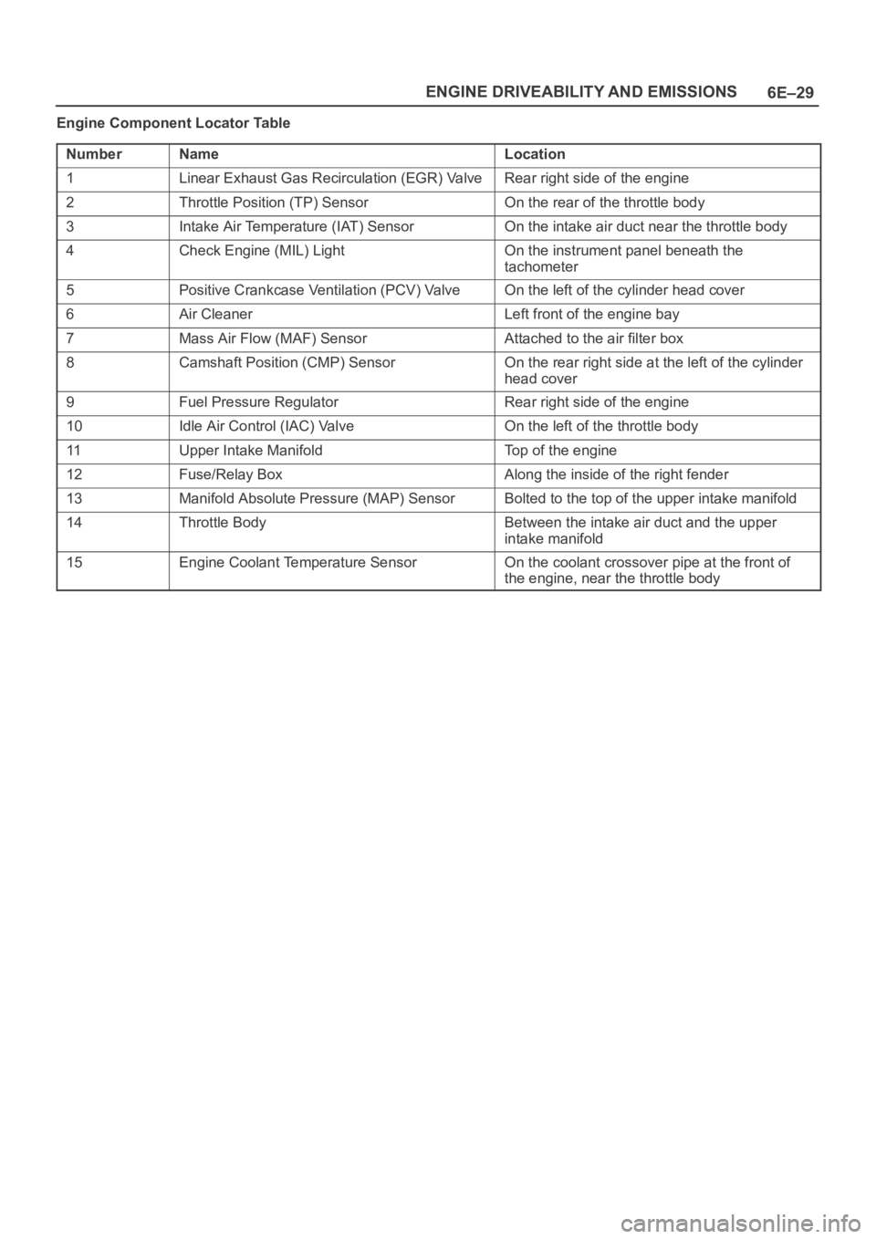
Engine Component Locator Table
Number
NameLocation
1Linear Exhaust Gas Recirculation (EGR) ValveRear right side of the engine
2Throttle Position (TP) SensorOn the rear of the throttle body
3Intake Air Temperature (IAT) SensorOn the intake air duct near the throttle body
4Check Engine (MIL) LightOn the instrument panel beneath the
tachometer
5Positive Crankcase Ventilation (PCV) ValveOn the left of the cylinder head cover
6Air CleanerLeft front of the engine bay
7Mass Air Flow (MAF) SensorAttached to the air filter box
8Camshaft Position (CMP) SensorOn the rear right side at the left of the cylinder
head cover
9Fuel Pressure RegulatorRear right side of the engine
10Idle Air Control (IAC) ValveOn the left of the throttle body
11Upper Intake ManifoldTop of the engine
12Fuse/Relay BoxAlong the inside of the right fender
13Manifold Absolute Pressure (MAP) SensorBolted to the top of the upper intake manifold
14Throttle BodyBetween the intake air duct and the upper
intake manifold
15Engine Coolant Temperature SensorOn the coolant crossover pipe at the front of
the engine, near the throttle body
Page 1148 of 6000
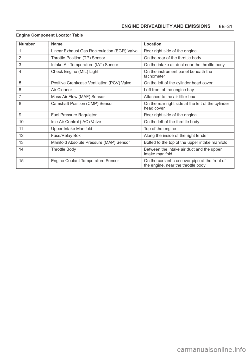
6E–31 ENGINE DRIVEABILITY AND EMISSIONS
Engine Component Locator Table
Number
NameLocation
1Linear Exhaust Gas Recirculation (EGR) ValveRear right side of the engine
2Throttle Position (TP) SensorOn the rear of the throttle body
3Intake Air Temperature (IAT) SensorOn the intake air duct near the throttle body
4Check Engine (MIL) LightOn the instrument panel beneath the
tachometer
5Positive Crankcase Ventilation (PCV) ValveOn the left of the cylinder head cover
6Air CleanerLeft front of the engine bay
7Mass Air Flow (MAF) SensorAttached to the air filter box
8Camshaft Position (CMP) SensorOn the rear right side at the left of the cylinder
head cover
9Fuel Pressure RegulatorRear right side of the engine
10Idle Air Control (IAC) ValveOn the left of the throttle body
11Upper Intake ManifoldTop of the engine
12Fuse/Relay BoxAlong the inside of the right fender
13Manifold Absolute Pressure (MAP) SensorBolted to the top of the upper intake manifold
14Throttle BodyBetween the intake air duct and the upper
intake manifold
15Engine Coolant Temperature SensorOn the coolant crossover pipe at the front of
the engine, near the throttle body
Page 1149 of 6000
6E–32
ENGINE DRIVEABILITY AND EMISSIONS
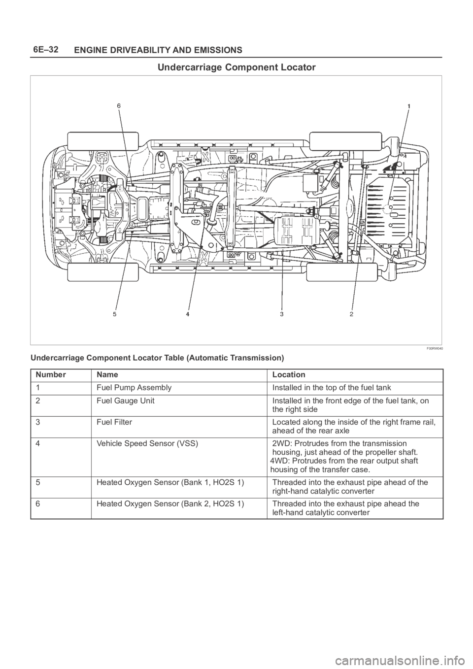
Undercarriage Component Locator
F00RW040
Undercarriage Component Locator Table (Automatic Transmission)
Number
NameLocation
1Fuel Pump AssemblyInstalled in the top of the fuel tank
2Fuel Gauge UnitInstalled in the front edge of the fuel tank, on
the right side
3Fuel FilterLocated along the inside of the right frame rail,
ahead of the rear axle
4Vehicle Speed Sensor (VSS)2WD: Protrudes from the transmission
housing, just ahead of the propeller shaft.
4WD: Protrudes from the rear output shaft
housing of the transfer case.
5Heated Oxygen Sensor (Bank 1, HO2S 1)Threaded into the exhaust pipe ahead of the
right-hand catalytic converter
6Heated Oxygen Sensor (Bank 2, HO2S 1)Threaded into the exhaust pipe ahead the
left-hand catalytic converter
Page 1150 of 6000
6E–33 ENGINE DRIVEABILITY AND EMISSIONS
Undercarriage Component Locator Table (Manual Transmission)
Number
NameLocation
1Fuel Pump AssemblyInstalled in the top of the fuel tank
2Fuel Gauge UnitInstalled in the front edge of the right frame
rail, ahead of the rear axle
3Fuel FilterLocated along the inside of the right frame rail,
ahead of the rear axle
4Vehicle Speed Sensor (VSS)2WD: Protrudes from the transmission
housing, just ahead of the propeller shaft.
4WD: Protrudes from the rear output shaft
housing of the transfer case.
5Heated Oxygen Sensor (Bank 1, HO2S 1)Threaded into the exhaust pipe ahead of the
right-hand catalytic converter
6Heated Oxygen Sensor (Bank 2, HO2S 1)Threaded into the exhaust pipe ahead of the
left-hand catalytic converter
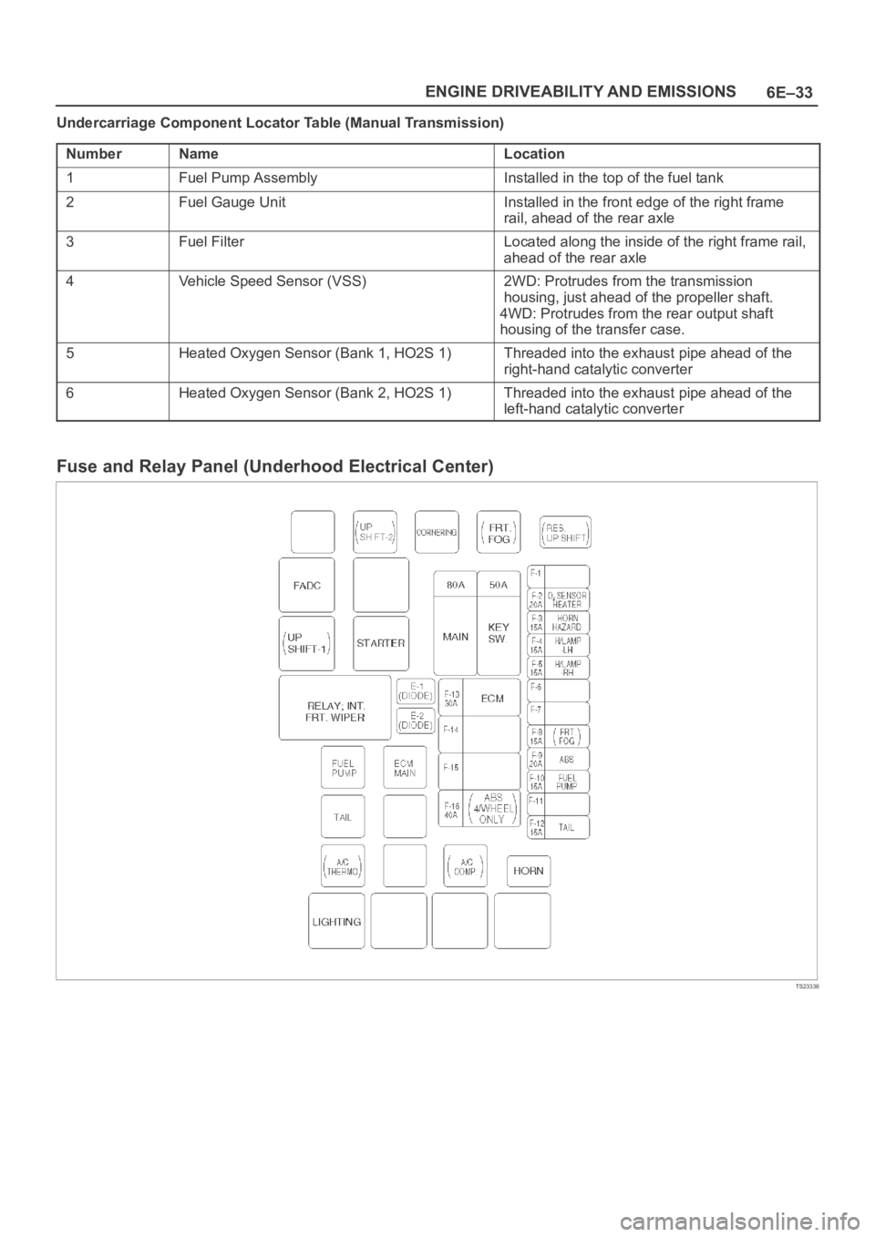
Fuse and Relay Panel (Underhood Electrical Center)
TS23336
Page 1155 of 6000
6E–38
ENGINE DRIVEABILITY AND EMISSIONS
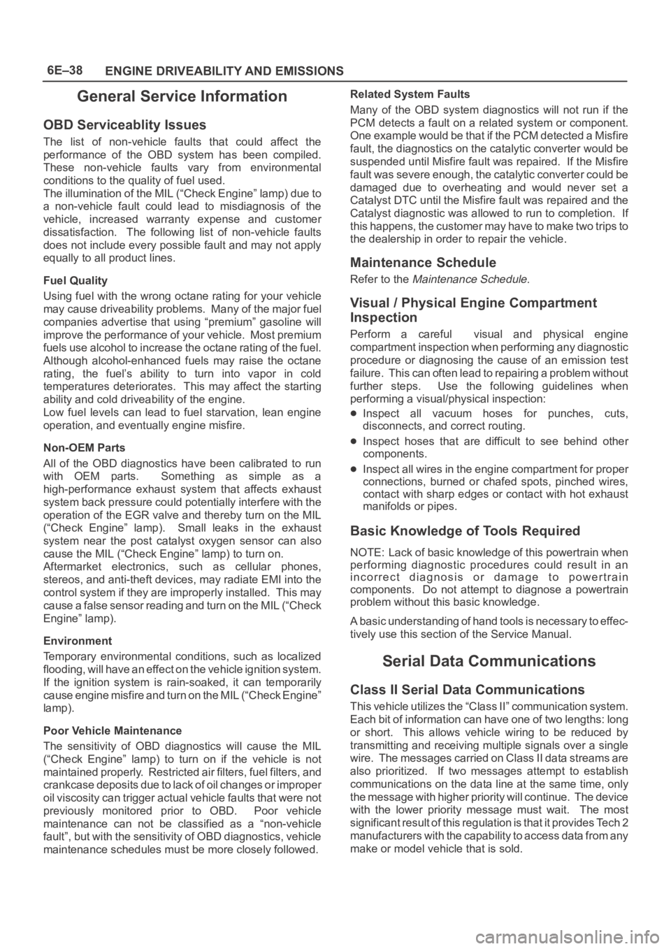
General Service Information
OBD Serviceablity Issues
The list of non-vehicle faults that could affect the
performance of the OBD system has been compiled.
These non-vehicle faults vary from environmental
conditions to the quality of fuel used.
The illumination of the MIL (“Check Engine” lamp) due to
a non-vehicle fault could lead to misdiagnosis of the
vehicle, increased warranty expense and customer
dissatisfaction. The following list of non-vehicle faults
does not include every possible fault and may not apply
equally to all product lines.
Fuel Quality
Using fuel with the wrong octane rating for your vehicle
may cause driveability problems. Many of the major fuel
companies advertise that using “premium” gasoline will
improve the performance of your vehicle. Most premium
fuels use alcohol to increase the octane rating of the fuel.
Although alcohol-enhanced fuels may raise the octane
rating, the fuel’s ability to turn into vapor in cold
temperatures deteriorates. This may affect the starting
ability and cold driveability of the engine.
Low fuel levels can lead to fuel starvation, lean engine
operation, and eventually engine misfire.
Non-OEM Parts
All of the OBD diagnostics have been calibrated to run
with OEM parts. Something as simple as a
high-performance exhaust system that affects exhaust
system back pressure could potentially interfere with the
operation of the EGR valve and thereby turn on the MIL
(“Check Engine” lamp). Small leaks in the exhaust
system near the post catalyst oxygen sensor can also
cause the MIL (“Check Engine” lamp) to turn on.
Aftermarket electronics, such as cellular phones,
stereos, and anti-theft devices, may radiate EMI into the
control system if they are improperly installed. This may
cause a false sensor reading and turn on the MIL (“Check
Engine” lamp).
Environment
Temporary environmental conditions, such as localized
flooding, will have an effect on the vehicle ignition system.
If the ignition system is rain-soaked, it can temporarily
cause engine misfire and turn on the MIL (“Check Engine”
lamp).
Poor Vehicle Maintenance
The sensitivity of OBD diagnostics will cause the MIL
(“Check Engine” lamp) to turn on if the vehicle is not
maintained properly. Restricted air filters, fuel filters, and
crankcase deposits due to lack of oil changes or improper
oil viscosity can trigger actual vehicle faults that were not
previously monitored prior to OBD. Poor vehicle
maintenance can not be classified as a “non-vehicle
fault”, but with the sensitivity of OBD diagnostics, vehicle
maintenance schedules must be more closely followed.Related System Faults
Many of the OBD system diagnostics will not run if the
PCM detects a fault on a related system or component.
One example would be that if the PCM detected a Misfire
fault, the diagnostics on the catalytic converter would be
suspended until Misfire fault was repaired. If the Misfire
fault was severe enough, the catalytic converter could be
damaged due to overheating and would never set a
Catalyst DTC until the Misfire fault was repaired and the
Catalyst diagnostic was allowed to run to completion. If
this happens, the customer may have to make two trips to
the dealership in order to repair the vehicle.
Maintenance Schedule
Refer to the Maintenance Schedule.
Visual / Physical Engine Compartment
Inspection
Perform a careful visual and physical engine
compartment inspection when performing any diagnostic
procedure or diagnosing the cause of an emission test
failure. This can often lead to repairing a problem without
further steps. Use the following guidelines when
performing a visual/physical inspection:
Inspect all vacuum hoses for punches, cuts,
disconnects, and correct routing.
Inspect hoses that are difficult to see behind other
components.
Inspect all wires in the engine compartment for proper
connections, burned or chafed spots, pinched wires,
contact with sharp edges or contact with hot exhaust
manifolds or pipes.
Basic Knowledge of Tools Required
NOTE: Lack of basic knowledge of this powertrain when
performing diagnostic procedures could result in an
incorrect diagnosis or damage to powertrain
components. Do not attempt to diagnose a powertrain
problem without this basic knowledge.
A basic understanding of hand tools is necessary to effec-
tively use this section of the Service Manual.
Serial Data Communications
Class II Serial Data Communications
This vehicle utilizes the “Class II” communication system.
Each bit of information can have one of two lengths: long
or short. This allows vehicle wiring to be reduced by
transmitting and receiving multiple signals over a single
wire. The messages carried on Class II data streams are
also prioritized. If two messages attempt to establish
communications on the data line at the same time, only
the message with higher priority will continue. The device
with the lower priority message must wait. The most
significant result of this regulation is that it provides Tech 2
manufacturers with the capability to access data from any
make or model vehicle that is sold.