1998 OPEL FRONTERA automatic transmission
[x] Cancel search: automatic transmissionPage 1144 of 6000
6E–27 ENGINE DRIVEABILITY AND EMISSIONS
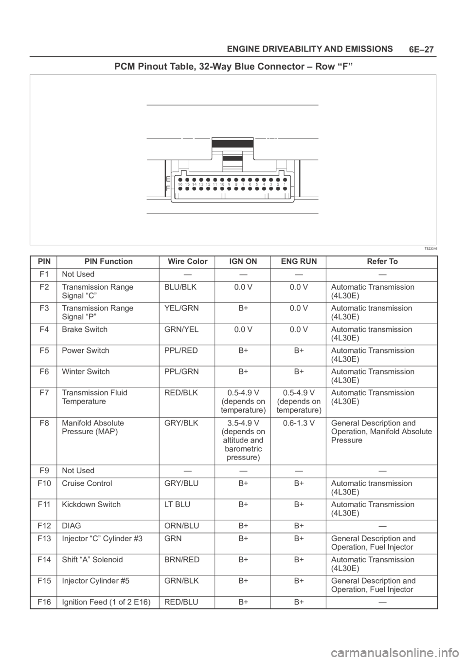
PCM Pinout Table, 32-Way Blue Connector – Row “F”
TS23346
PINPIN FunctionWire ColorIGN ONENG RUNRefer To
F1Not Used————
F2Transmission Range
Signal “C”BLU/BLK0.0 V0.0 VAutomatic Transmission
(4L30E)
F3Transmission Range
Signal “P”YEL/GRNB+0.0 VAutomatic transmission
(4L30E)
F4Brake SwitchGRN/YEL0.0 V0.0 VAutomatic transmission
(4L30E)
F5Power SwitchPPL/REDB+B+Automatic Transmission
(4L30E)
F6Winter SwitchPPL/GRNB+B+Automatic Transmission
(4L30E)
F7Transmission Fluid
TemperatureRED/BLK0.5-4.9 V
(depends on
temperature)0.5-4.9 V
(depends on
temperature)Automatic Transmission
(4L30E)
F8Manifold Absolute
Pressure (MAP)GRY/BLK3.5-4.9 V
(depends on
altitude and
barometric
pressure)0.6-1.3 VGeneral Description and
Operation, Manifold Absolute
Pressure
F9Not Used————
F10Cruise ControlGRY/BLUB+B+Automatic transmission
(4L30E)
F11Kickdown SwitchLT B L UB+B+Automatic Transmission
(4L30E)
F12DIAGORN/BLUB+B+—
F13Injector “C” Cylinder #3GRNB+B+General Description and
Operation, Fuel Injector
F14Shift “A” SolenoidBRN/REDB+B+Automatic Transmission
(4L30E)
F15Injector Cylinder #5GRN/BLKB+B+General Description and
Operation, Fuel Injector
F16Ignition Feed (1 of 2 E16)RED/BLUB+B+—
Page 1149 of 6000
6E–32
ENGINE DRIVEABILITY AND EMISSIONS
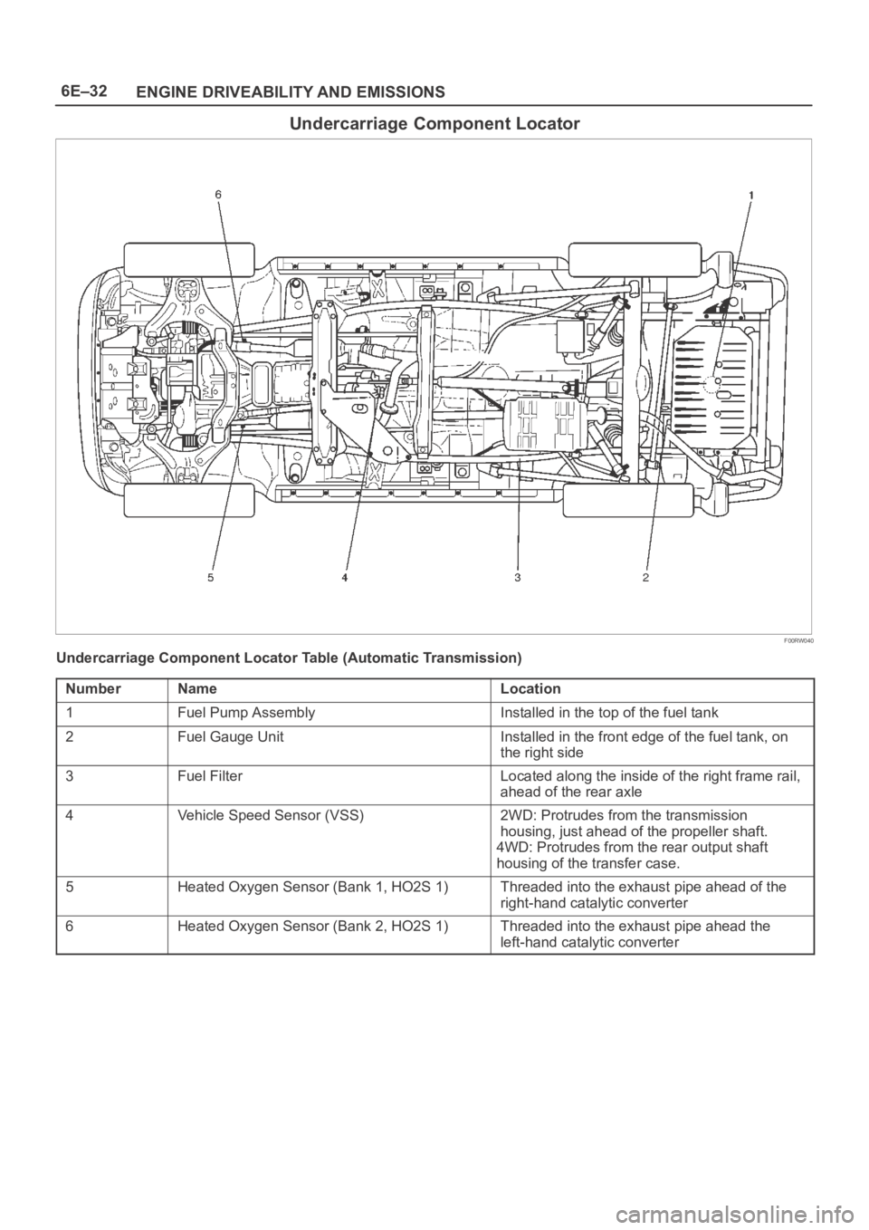
Undercarriage Component Locator
F00RW040
Undercarriage Component Locator Table (Automatic Transmission)
Number
NameLocation
1Fuel Pump AssemblyInstalled in the top of the fuel tank
2Fuel Gauge UnitInstalled in the front edge of the fuel tank, on
the right side
3Fuel FilterLocated along the inside of the right frame rail,
ahead of the rear axle
4Vehicle Speed Sensor (VSS)2WD: Protrudes from the transmission
housing, just ahead of the propeller shaft.
4WD: Protrudes from the rear output shaft
housing of the transfer case.
5Heated Oxygen Sensor (Bank 1, HO2S 1)Threaded into the exhaust pipe ahead of the
right-hand catalytic converter
6Heated Oxygen Sensor (Bank 2, HO2S 1)Threaded into the exhaust pipe ahead the
left-hand catalytic converter
Page 1190 of 6000
6E–73 ENGINE DRIVEABILITY AND EMISSIONS
Te c h 2
ParameterRefer To Typical Data
Va l u e s
(2500 RPM) Typical Data
Values (IDLE) Units
Displayed Data List
Start-Up ECT
(Engine Coolant
Te m p )EngineDegrees C,
Degrees FDepends on
engine coolant
temperature at
time of start-upDepends on
engine coolant
temperature at
time of start-upGeneral Description and
Operation, Engine Coolant
Temperature (ECT) Sensor
Start-Up IAT
(Intake Air
Te m p )EngineDegrees C,
Degrees FDepends on
intake air
temperature at
time of start-upDepends on
intake air
temperature at
time of start-upGeneral Description and
Operation, Intake Air
Temperature (IAT) Sensor
TP
(Throttle
Position)EnginePercent0
—
General Description and
Operation, Throttle
Position (TP) Sensor;
DTCs: P0121,
P0122,P0123
TP Sensor
(Throttle
Position)EngineVo l t s0.50-0.820.60-1.00General Description and
Operation, Throttle
Position (TP) Sensor;
DTCs: P0121,
P0122,P0123
Catalyst
Protection ModeEngineNo/YesNoNoGeneral Description, Fuel
Metering, catalytic
Converter Protection Mode
Vehicle SpeedEngineMPH /
km/h004L30-E Automatic
Transmission Diagnosis
EVAP Purge
SolenoidEnginePercent6599General Description
VIM SolenoidEngineOn/OffOnOnGeneral Description
Security Wait
TimeEngineActive/Inac
tiveInactiveInactive—
Page 1271 of 6000
6E–154
ENGINE DRIVEABILITY AND EMISSIONS
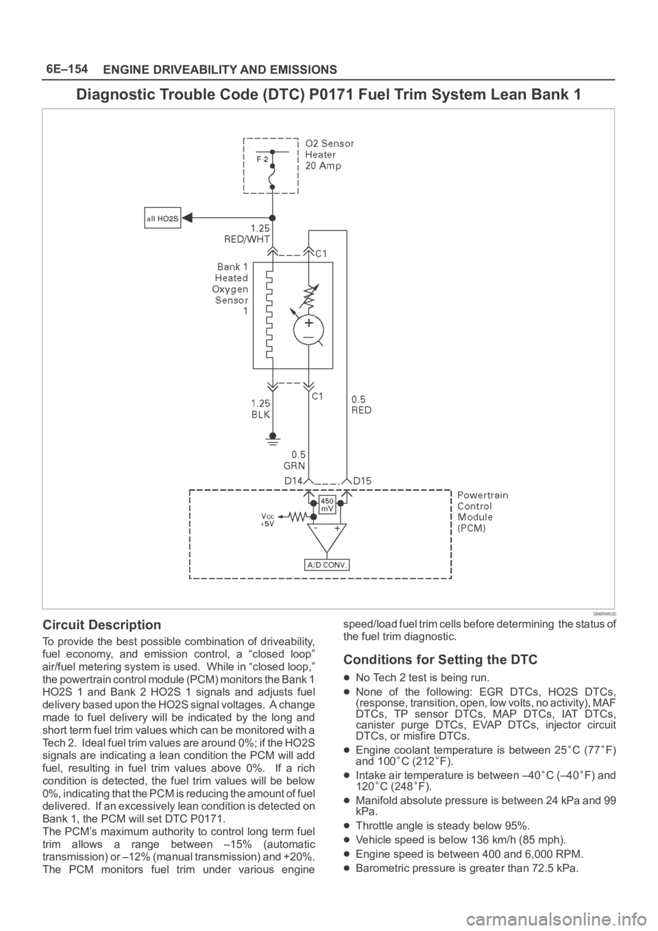
Diagnostic Trouble Code (DTC) P0171 Fuel Trim System Lean Bank 1
D06RW030
Circuit Description
To provide the best possible combination of driveability,
fuel economy, and emission control, a “closed loop”
air/fuel metering system is used. While in “closed loop,”
the powertrain control module (PCM) monitors the Bank 1
HO2S 1 and Bank 2 HO2S 1 signals and adjusts fuel
delivery based upon the HO2S signal voltages. A change
made to fuel delivery will be indicated by the long and
short term fuel trim values which can be monitored with a
Tech 2. Ideal fuel trim values are around 0%; if the HO2S
signals are indicating a lean condition the PCM will add
fuel, resulting in fuel trim values above 0%. If a rich
condition is detected, the fuel trim values will be below
0%, indicating that the PCM is reducing the amount of fuel
delivered. If an excessively lean condition is detected on
Bank 1, the PCM will set DTC P0171.
The PCM’s maximum authority to control long term fuel
trim allows a range between –15% (automatic
transmission) or –12% (manual transmission) and +20%.
The PCM monitors fuel trim under various enginespeed/load fuel trim cells before determining the status of
the fuel trim diagnostic.
Conditions for Setting the DTC
No Tech 2 test is being run.
None of the following: EGR DTCs, HO2S DTCs,
(response, transition, open, low volts, no activity), MAF
DTCs, TP sensor DTCs, MAP DTCs, IAT DTCs,
canister purge DTCs, EVAP DTCs, injector circuit
DTCs, or misfire DTCs.
Engine coolant temperature is between 25C (77F)
and 100C (212F).
Intake air temperature is between –40C (–40F) and
120C (248F).
Manifold absolute pressure is between 24 kPa and 99
kPa.
Throttle angle is steady below 95%.
Vehicle speed is below 136 km/h (85 mph).
Engine speed is between 400 and 6,000 RPM.
Barometric pressure is greater than 72.5 kPa.
Page 1275 of 6000
6E–158
ENGINE DRIVEABILITY AND EMISSIONS
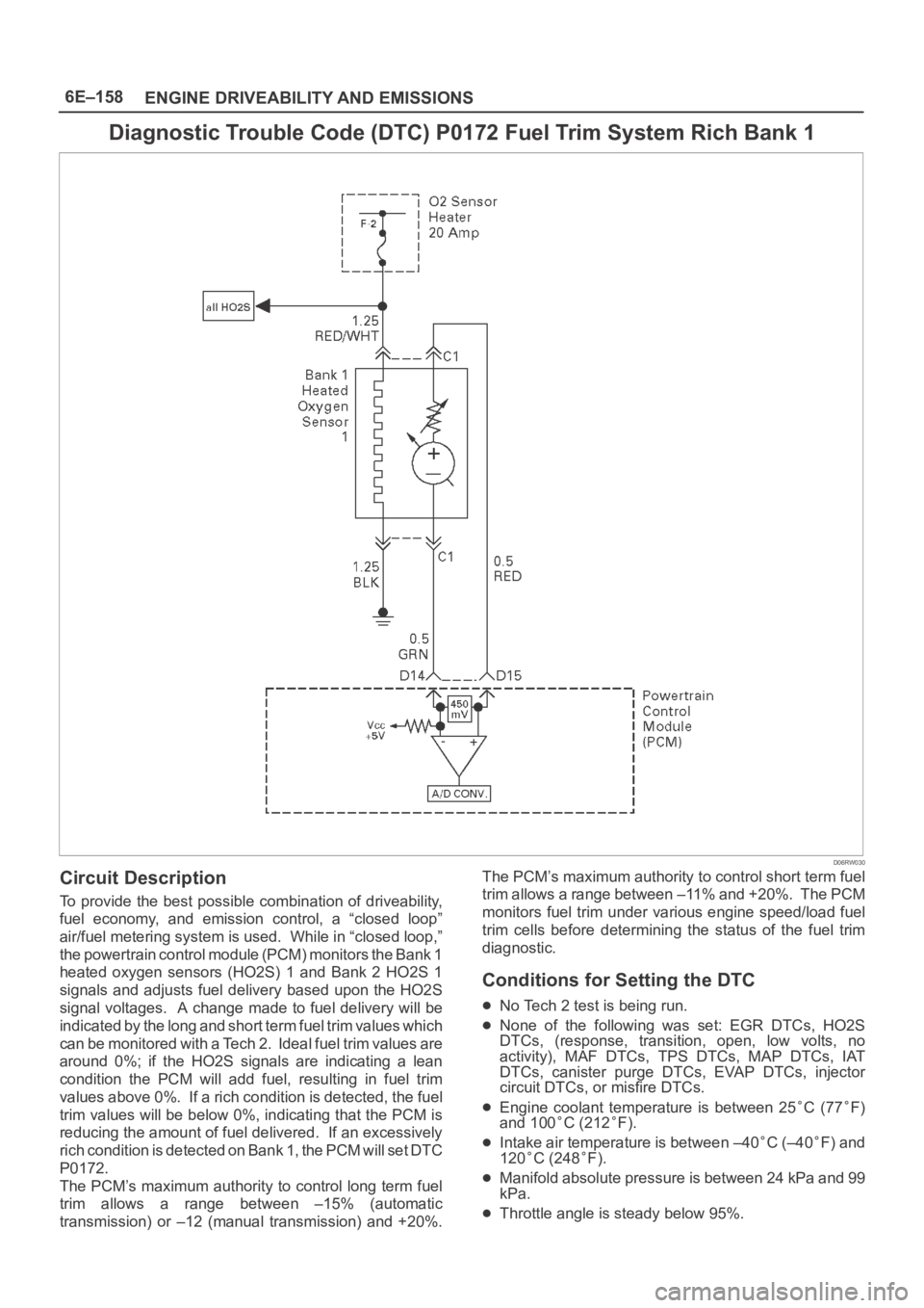
Diagnostic Trouble Code (DTC) P0172 Fuel Trim System Rich Bank 1
D06RW030
Circuit Description
To provide the best possible combination of driveability,
fuel economy, and emission control, a “closed loop”
air/fuel metering system is used. While in “closed loop,”
the powertrain control module (PCM) monitors the Bank 1
heated oxygen sensors (HO2S) 1 and Bank 2 HO2S 1
signals and adjusts fuel delivery based upon the HO2S
signal voltages. A change made to fuel delivery will be
indicated by the long and short term fuel trim values which
can be monitored with a Tech 2. Ideal fuel trim values are
around 0%; if the HO2S signals are indicating a lean
condition the PCM will add fuel, resulting in fuel trim
values above 0%. If a rich condition is detected, the fuel
trim values will be below 0%, indicating that the PCM is
reducing the amount of fuel delivered. If an excessively
rich condition is detected on Bank 1, the PCM will set DTC
P0172.
The PCM’s maximum authority to control long term fuel
trim allows a range between –15% (automatic
transmission) or –12 (manual transmission) and +20%.The PCM’s maximum authority to control short term fuel
trim allows a range between –11% and +20%. The PCM
monitors fuel trim under various engine speed/load fuel
trim cells before determining the status of the fuel trim
diagnostic.
Conditions for Setting the DTC
No Tech 2 test is being run.
None of the following was set: EGR DTCs, HO2S
DTCs, (response, transition, open, low volts, no
activity), MAF DTCs, TPS DTCs, MAP DTCs, IAT
DTCs, canister purge DTCs, EVAP DTCs, injector
circuit DTCs, or misfire DTCs.
Engine coolant temperature is between 25C (77F)
and 100C (212F).
Intake air temperature is between –40C (–40F) and
120
C (248F).
Manifold absolute pressure is between 24 kPa and 99
kPa.
Throttle angle is steady below 95%.
Page 1279 of 6000

6E–162
ENGINE DRIVEABILITY AND EMISSIONS
Diagnostic Trouble Code (DTC) P0174 Fuel Trim System Lean Bank 2
D06RW031
Circuit Description
To provide the best possible combination of driveability,
fuel economy, and emission control, a “closed loop”
air/fuel metering system is used. While in “closed loop,”
the powertrain control module (PCM) monitors the Bank 1
HO2S 1 and Bank 2 HO2S 1 signals and adjusts fuel
delivery based upon the HO2S signal voltages. A change
made to fuel delivery will be indicated by the long and
short term fuel trim values which can be monitored with a
Tech 2. Ideal fuel trim values are around 0%; if the HO2S
signals are indicating a lean condition the PCM will add
fuel, resulting in fuel trim values above 0%. If a rich
condition is detected, the fuel trim values will be below
0%, indicating that the PCM is reducing the amount of fuel
delivered. If an excessively lean condition is detected on
Bank 2, the PCM will set DTC P0174.
The PCM’s maximum authority to control long term fuel
trim allows a range between –15%(automatic
transmission) or –12%(manual transmission) and +20%.
The PCM monitors fuel trim under various enginespeed/load fuel trim cells before determining the status of
the fuel trim diagnostic.
Conditions for Setting the DTC
No Tech 2 test is being run.
None of the following DTCs are set: idle system, EGR,
HO2S, (response, transition, open, low volts, no
activity), MAF, TP sensor, MAP, IAT, canister purge,
EVAP, injector circuit, or misfire.
Engine coolant temperature is between 25C (77F)
and 100C (212F).
Intake air temperature is between –40C (–40F) and
120C (248F).
Manifold absolute pressure is between 24 kPa and 99
kPa.
Throttle angle is steady below 95%.
Vehicle speed is below 136 km/h (85 mph).
Engine speed is between 400 and 6,000 RPM.
Barometric pressure is greater than 72.5 kPa.
Mass air flow is between 2 g/second and 200 g/second.
Page 1283 of 6000
6E–166
ENGINE DRIVEABILITY AND EMISSIONS
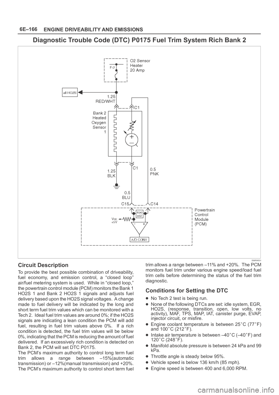
Diagnostic Trouble Code (DTC) P0175 Fuel Trim System Rich Bank 2
D06RW031
Circuit Description
To provide the best possible combination of driveability,
fuel economy, and emission control, a “closed loop”
air/fuel metering system is used. While in “closed loop,”
the powertrain control module (PCM) monitors the Bank 1
HO2S 1 and Bank 2 HO2S 1 signals and adjusts fuel
delivery based upon the HO2S signal voltages. A change
made to fuel delivery will be indicated by the long and
short term fuel trim values which can be monitored with a
Tech 2. Ideal fuel trim values are around 0%; if the HO2S
signals are indicating a lean condition the PCM will add
fuel, resulting in fuel trim values above 0%. If a rich
condition is detected, the fuel trim values will be below
0%, indicating that the PCM is reducing the amount of fuel
delivered. If an excessively rich condition is detected on
Bank 2, the PCM will set DTC P0175.
The PCM’s maximum authority to control long term fuel
trim allows a range between –15%(automatic
transmission) or –12%(manual transmission) and +20%.
The PCM’s maximum authority to control short term fueltrim allows a range between –11% and +20%. The PCM
monitors fuel trim under various engine speed/load fuel
trim cells before determining the status of the fuel trim
diagnostic.
Conditions for Setting the DTC
No Tech 2 test is being run.
None of the following DTCs are set: idle system, EGR,
HO2S, (response, transition, open, low volts, no
activity), MAF, TPS, MAP, IAT, canister purge, EVAP,
injector circuit, or misfire.
Engine coolant temperature is between 25C (77F)
and 100C (212F).
Intake air temperature is between –40C (–40F) and
120
C (248F).
Manifold absolute pressure is between 24 kPa and 99
kPa.
Throttle angle is steady below 95%.
Vehicle speed is below 136 km/h (85 mph).
Engine speed is between 400 and 6,000 RPM.
Page 1358 of 6000
6E–241 ENGINE DRIVEABILITY AND EMISSIONS
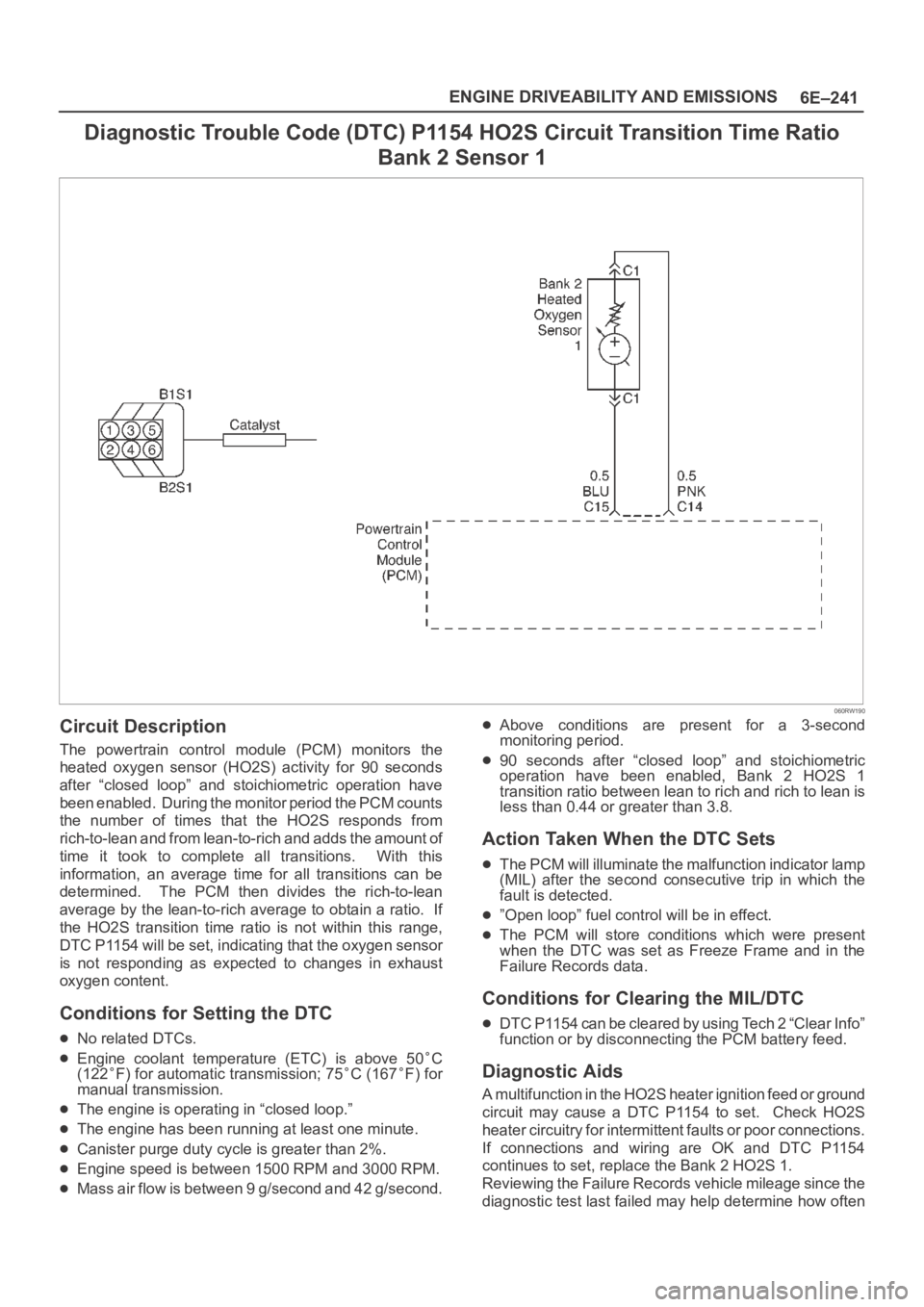
Diagnostic Trouble Code (DTC) P1154 HO2S Circuit Transition Time Ratio
Bank 2 Sensor 1
060RW190
Circuit Description
The powertrain control module (PCM) monitors the
heated oxygen sensor (HO2S) activity for 90 seconds
after “closed loop” and stoichiometric operation have
been enabled. During the monitor period the PCM counts
the number of times that the HO2S responds from
rich-to-lean and from lean-to-rich and adds the amount of
time it took to complete all transitions. With this
information, an average time for all transitions can be
determined. The PCM then divides the rich-to-lean
average by the lean-to-rich average to obtain a ratio. If
the HO2S transition time ratio is not within this range,
DTC P1154 will be set, indicating that the oxygen sensor
is not responding as expected to changes in exhaust
oxygen content.
Conditions for Setting the DTC
No related DTCs.
Engine coolant temperature (ETC) is above 50C
(122F) for automatic transmission; 75C (167F) for
manual transmission.
The engine is operating in “closed loop.”
The engine has been running at least one minute.
Canister purge duty cycle is greater than 2%.
Engine speed is between 1500 RPM and 3000 RPM.
Mass air flow is between 9 g/second and 42 g/second.
Above conditions are present for a 3-second
monitoring period.
90 seconds after “closed loop” and stoichiometric
operation have been enabled, Bank 2 HO2S 1
transition ratio between lean to rich and rich to lean is
less than 0.44 or greater than 3.8.
Action Taken When the DTC Sets
The PCM will illuminate the malfunction indicator lamp
(MIL) after the second consecutive trip in which the
fault is detected.
”Open loop” fuel control will be in effect.
The PCM will store conditions which were present
when the DTC was set as Freeze Frame and in the
Failure Records data.
Conditions for Clearing the MIL/DTC
DTC P1154 can be cleared by using Tech 2 “Clear Info”
function or by disconnecting the PCM battery feed.
Diagnostic Aids
A multifunction in the HO2S heater ignition feed or ground
circuit may cause a DTC P1154 to set. Check HO2S
heater circuitry for intermittent faults or poor connections.
If connections and wiring are OK and DTC P1154
continues to set, replace the Bank 2 HO2S 1.
Reviewing the Failure Records vehicle mileage since the
diagnostic test last failed may help determine how often