1998 OPEL FRONTERA fuel
[x] Cancel search: fuelPage 1746 of 6000

ENGINE MECHANICAL 6A – 13
VALVE CLEARANCE ADJUSTMENT
1. Install 2.80 mm valve adjuster (shim) first when
reassembling the engine.
Thickness mark faces down.
2. Measure the valve clearance after installing cam
carrier assy with camshafts.
3. Change the adjuster using a special tool when the
clearance is out of tolerance.
Valve Clearance Adjusting Tool: 5-8840-2590-0
VALVE CLEARANCE (When cold condition)
Inlet 0.15 ± 0.05 mm
Exh 0.25 ± 0.05 mm
COMPRESSION PRESSURE
MEASUREMENT
1. Start the engine and allow it to idle until the coolant
temperature reaches 70 – 80°C (158 – 176°F).
2. Remove the following parts.
Glow plugs
Fuel cut solenoid connector
QOS (Quick-On Start System) fuse in the fuse
box.
3. Set the adapter and compression gauge to the No.
1 cylinder glow plug hole.
Compression Gauge
(with Adapter): 5-8840-2008-0
4. Turn the engine over with the starter motor and take
the compression gauge reading.
Compression Pressure at 200 rpm
Standard: 3040 kPa (31 kg/cm
2/441 psi)
Limit: 2160 kPa (22 kg/cm
2/313 psi)
5. Repeat the procedure (Steps 3 and 4) for the
remaining cylinders.
QUICK-ON START 4 SYSTEM
Quick-On Start System Inspection Procedure
1. Disconnect the ECT-sensor connection around the
thermostat outlet pipe.
2. Turn the starter switch to the “ON” position.
If the Quick-On Start 4 System is operating
properly, the glow relay will make a clicking sound
within seven seconds after the starter switch is
turned on.
3. Measure the glow plug terminal voltage with a
circuit tester immediately after turning the starter
switch to the “ON” position.
Glow Plug Terminal Voltage: approx. 12V
NOTE: Electrical power to the quick-on start system will
be cut after the starter has remained in the “ON”
position for twenty seconds.
Turn the starter switch to the “OFF” position and back
to the “ON” position.
This will reset the Quick-On Start 4 System.
014RW150
Page 1762 of 6000
ENGINE MECHANICAL 6A – 29
13 Vacuum Hose
1) Disconnect vacuum hose from vacuum pump.
14. Starter Harness
1) Disconnect B terminal and put cable harness
close to chassis side.
2) Disconnect S terminal connector.
15. Engine Harness
1) Disconnect engine harness close to engine side.
16. Fuel Pipe
1) Remove fuel pipe from fuel pump and take care
not to spill fuel and let dust enter.
17. Engine Ground Cable
1) Disconnect ground cable from left rear side of
timing gear case.
18. Vacuum Hose: Vacuum Tank
Disconnect vacuum hose from vacuum pump side.
19. Glow Plug Harness
20. Transmission Assembly
1) Set transmission support tool under the
transmission.
2) Remove transmission rear mount.
3) Remove transmission fixing bolt from rear of
engine assembly except two bolts.
4) Carefully hang up engine assembly with a hoist.
5) Remove remaining two transmission fixing bolts.
6) Remove transmission assembly.
7) Remove heater hose.
8) Disconnect wire harness connector for shift on
the fly.
9) Remove vacuum hose.
21. Prepare Engine Stand
22. Engine Assembly
1) Remove engine mount fixing bolts.
2) Carefully hang up the engine assembly.
3) Take out the engine assembly making sure not
to damage the brake oil pipe and other pipe etc.
INSTALLATION
1. Engine assembly
1) Install engine in mounting position by using
hoist.
2. Transmission Assembly
1) Refer to transmission installation steps in
section 7.
3. Engine Mounting
1) After all fixing bolts (left: two bolts, rights: two
bolts) were inserted in every hole, tighten fixing
bolts to the specified torque.
Torque: 40 Nꞏm (4 kgꞏm/29 lbꞏft)
4. Glow Plug Harness
5. Vacuum Hose
1) Connect Vacuum Hose to Vacuum Pump
6. Engine Ground Cable
7. Fuel Pipe
1) Install fuel pipe to fuel pump.
8. Engine Harness
9. Starter Harness
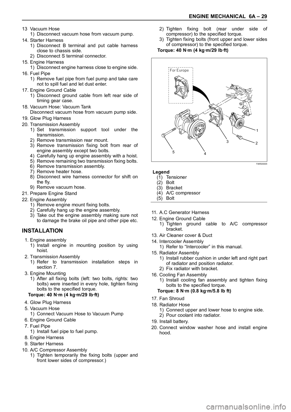
10. A/C Compressor Assembly
1) Tighten temporarily the fixing bolts (upper and
front lower sides of compressor.)2) Tighten fixing bolt (rear under side of
compressor) to the specified torque.
3) Tighten fixing bolts (front upper and lower sides
of compressor) to the specified torque.
To r q u e : 4 0 N ꞏm ( 4 k g ꞏm / 2 9 l b ꞏf t )
Legend
(1) Tensioner
(2) Bolt
(3) Bracket
(4) A/C compressor
(5) Bolt
11. A.C Generator Harness
12. Engine Ground Cable
1) Tighten ground cable to A/C compressor
bracket.
13. Air Cleaner cover & Duct
14. Intercooler Assembly
1) Refer to “Intercooler” in this manual.
15. Radiator Assembly
1) Install rubber cushion in under left and right part
of radiator and position radiator.
2) Fix radiator with bracket.
16. Cooling Fan Assembly
1) Install cooling fan assembly and tighten fixing
bolts to the specified torque.
Torque: 8 Nꞏm (0.8 kgꞏm/5.8 lb ft)
17. Fan Shroud
18. Radiator Hose
1) Connect upper and lower hose to engine side.
2) Pour coolant into radiator.
19. Install battery.
20. Connect window washer hose and install engine
hood.
1
2
3
4
5
For E urope
F06R200005
Page 1768 of 6000

ENGINE MECHANICAL 6A – 35
INTAKE MANIFOLD
REMOVAL
1. Drain engine coolant and disconnect water hose
from thermostat hosing.
2. Remove intercooler assembly
Refer to “Intercooler” in this manual.
3. Remove bracket bolt of oil level gauge guide tube.
4. Remove PCV Hose.
5. Remove hoses from EGR, EGR vacuum sensor
and inlet/outlet of heater.
6. Disconnect harness connector form MAP sensor,
EGR vacuum sensor, ETC sensor, water
temperature unit, IAT sensor and EVRV.
7. Remove high pressure oil pipe.
8. Remove the two way valve.
9. Remove fuel pipe from between intake manifold
and high pressure oil pump.
10. Remove fixing bolts and nuts on the intake
manifold, then remove the intake manifold
assembly.
INSTALLATION
1. Install the intake manifold, tighten bolts and nuts to
the specified torque.
Torque : 20 Nꞏm (2.0 kgꞏm/14.5 lb ft) for bolt and nut
2. Install the fuel pipe and tighten to the specified
torque.To r q u e :
M16 bolt (apply engine oil) 4 Nꞏm (0.4 kgꞏm/2.9
lb ft)
Cap nut (M10) 13Nꞏm (1.3 kgꞏm/9.4 lb ft)
Fuel pipe (M10 apply engine oil) 14 Nꞏm (1.4
kgꞏm/10 lb ft)
3. Install two way valve.
Torque : 20 Nꞏm (2.0 kgꞏm/14.5 lb ft)
4. Fill with about 300 cc of engine oil from the high
pressure oil pipe installation port of the oil rail using
an oil filler. If assembled without filling the oil rail
with oil, the time for starting the engine will be
longer.
5. Install the high pressure oil pipe immediately and
tighten the sleeve nut to the specified torque.
Torque : 80 Nꞏm (8 kgꞏm/57.9 lb ft)
6. Reconnect harness connector to MAP sensor, EGR
vacuum sensor, ETC sensor, Water temperature
unit, IAT sensor and EVRV.
7. Connect the hoses to EGR valve, EGR vacuum
sensor, and water inlet/outlet pipe for heater.
8. Connect PCV hose.
9. Install the oil level gauge guide tube and tighten
bracket bolt.
10. Install the intercooler assembly.
Refer to “Intercooler” in this manual.
11. Connect the hose to the thermostat housing and fill
with engine coolant.
For Europe
2
1
3
3 1 42
025R200005
Legend
(1) Intake Manifold
(2) Throttle Valve Assembly
(3) EGR Valve
(4) Gasket
Page 1777 of 6000
6A – 44 ENGINE MECHANICAL
REMOVAL
1. Disconnect battery ground cable.
2. Drain engine coolant.
3. Remove air cleaner and air duct.
4. Remove intercooler assembly.
Refer to “Intercooler” in this manual.
5. Remove oil level gauge guide assembly.
6. Remove PCV hose.
7. Remove EGR vacuum hose.
8. Disconnect harness connector around the cylinder
head.
9. Remove A/C compressor assembly.
10. Remove A/C compressor bracket.
11. Remove generator assembly and take out fan belt.
12. Remove heat protector and remove valve
assembly.
13. Remove water hose and oil pipe from turbocharger.
14. Remove turbocharger assembly.
15. Remove water hose between thermostat and
radiator.
16. Remove cylinder head noise insulator cover.
NOTE: Do not make damage to the harness.
17. Remove high pressure pipe.
18. Remove timing belt cover.
19. Remove CMP sensor bracket.
20. Remove timing belt tensioner and remove timing
belt.
21. Remove camshaft pulley.
22. Remove front plate.
23. Remove water pipe between cylinder head and
water pump.
24. Remove fuel pipe between fuel pump and intake
manifold.
25. Remove fuel return pipe.
26. Remove intake manifold assembly.
27. Disconnect glow plug wiring and remove glow plug.
28. Remove cylinder head cover.
29. Drain oil from oil rail.
30. Disconnect injector harness connector.
31. Disconnect harness connector from oil pressure
sensor and oil temperature sensor on the oil rail.
32. Disconnect injector harness assembly.
33. Remove injector clamp.
34. Remove injector spacer (If equipped.).
35. Remove injector assembly.
36. Remove oil rail assembly.
37. Remove camshaft carrier.
38. Remove cylinder head assembly.
39. Remove cylinder gasket.
INSTALLATION
1. Install cylinder head gasket with top mark up.
NOTE: Determine cylinder head gasket grade by
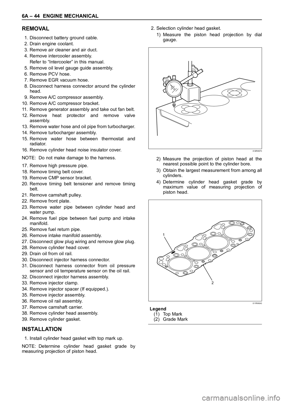
measuring projection of piston head.2. Selection cylinder head gasket.
1) Measure the piston head projection by dial
gauge.
2) Measure the projection of piston head at the
nearest possible point to the cylinder bore.
3) Obtain the largest measurement from among all
cylinders.
4) Determine cylinder head gasket grade by
maximum value of measuring projection of
piston head.
Legend
(1) Top Mark
(2) Grade Mark
012RW073
2 1
011RW043
Page 1778 of 6000

ENGINE MECHANICAL 6A – 45
Cylinder head gasket and piston projection mm
CAUTION:
The projection of each piston should be 0.333
mm or more and less than 0.483 mm.
Maximum difference in projection between
pistons should be less than 0.1 mm.
If the piston projection is without standard,
reassemble the engine all over again.
3. Install cylinder head assembly, tighten bolts by
angular tightening method.
To r q u e :
1st step; 49 Nꞏm (4.9 kgꞏm/35.4 lb ft)
2nd step; 60°
3rd step; 60°
CAUTION: The cylinder head bolts cannot be
reused.
4. Install camshaft carrier assembly.
Refer to “Camshaft” in this manual.
5. Install oil rail and injector assembly.
Refer to “Oil rail and injector” in this manual.
6. Install injector harness to connect harness
connector.
Note: Apply liquid gasket (TB 1207B or equivalent) to
the rubber seal of the camshaft end, injector harness
gasket area and No. 1 camshaft bracket. Refer to the
Cylinder head cover.
7. Install cylinder head cover.
Torque: 9 Nꞏm (0.9 kgꞏm/6.5 lb ft)
8. Install glow plug to tighten specified torque.
Torque: 15 Nꞏm (1.5 kgꞏm/11 lb ft) and connectglow plug harness.
9. Install intake manifold.
Torque: 20 Nꞏm (2.0 kgꞏm/14.5 lb ft)
10. Install fuel return pipe.
11. Install fuel pipe in between fuel pump and intake
manifold.
12. Install water pipe in between cylinder head and
water pump.
Tighten flange bolt to the specified torque.
Torque: 20 Nꞏm (2.0 kgꞏm/14.5 lb ft)
13. Install front plate.
Torque: 20 Nꞏm (2.0 kgꞏm/14.5 lb ft)
14. Install camshaft pulley, tighten with angular
tightening method.
1st step 40 Nꞏm (4.0 kgꞏm/29 lb ft)
2nd step 60°
NOTE: Apply engine oil to camshaft pulley bolt.
15. Align timing mark oil pump pulley and camshaft
pulley to front plate then put the timing belt and
tighten tensioner bolt.
Torque: 20 Nꞏm (2.0 kgꞏm/14.5 lb ft) for M8
50 Nꞏm (5.1 kgꞏm/37 lb ft)
16. Install CMP sensor bracket.
17. Install timing belt cover.
Torque: 9 Nꞏm (0.9 kgꞏm/6.5 lb ft)
18. Fill with about 300 cc of engine oil from the high
pressure oil pipe installing port of oil rail using an oil
filler.
If assembled without filling the oil rail with oil, the
time for engine start will be longer.
19. Immediately install high pressure oil pipe to tighten
with specified torque.
Torque: 80 Nꞏm (8 kgꞏm/57.9 lb ft)
20. Install cylinder head noise insulator cover.
Torque: 9 Nꞏm (0.9 kgꞏm/6.5 lb ft)
Grade A Grade B Grade C
011RW042
Grade Piston projectionGasket
thickness
A more 0.333 to less 0.383 1.35
B more 0.383 to less 0.433 1.40
C more 0.433 to less 0.483 1.45
Page 1793 of 6000
6A – 60 ENGINE MECHANICAL
VALVE STEM SEAL, VALVE SPRING AND ADJUSTER
REMOVAL
1. Disconnect battery ground cable.
2. Drain engine coolant.
3. Remove the air duct from between air cleaner and
turbocharger.
4. Remove intercooler assembly.
Refer to “Intercooler” in this manual.
5. Remove oil level gauge guide assembly.
6. Disconnect PCV hose.
7. Disconnect EGR vacuum hose.
8. Disconnect harness connectors around the cylinder
head such as the injector, CMP sensor, MAP
sensor, EGR sensor, EVRV, IAT sensor, A/C
compressor, TP stepping motor, TP sensor and fuel
temperature sensor etc.
9. Remove A/C compressor assembly.
10. Remove A/C compressor bracket.
11. Remove generator assembly and take out drivebelt.
12. Remove heat protector, remove exhaust valve
assembly.
13. Remove water cooling hose and lubrication pipe for
turbocharger.
14. Remove turbocharger assembly.
15. Remove hose between thermostat and radiator.
16. Remove noise insulator cover of cylinder head.
NOTE: Do not damage injector harness.
17. Remove high pressure oil pipe.
18. Remove timing belt cover.
19. Remove CMP sensor bracket.
20. Remove timing belt tensioner then remove timing
belt.
21. Remove camshaft pulley.
22. Remove front plate.
23. Remove engine coolant pipe between cylinder
head and water pump.
1
2
3
4
5
6
9
10
7
8
011RW031
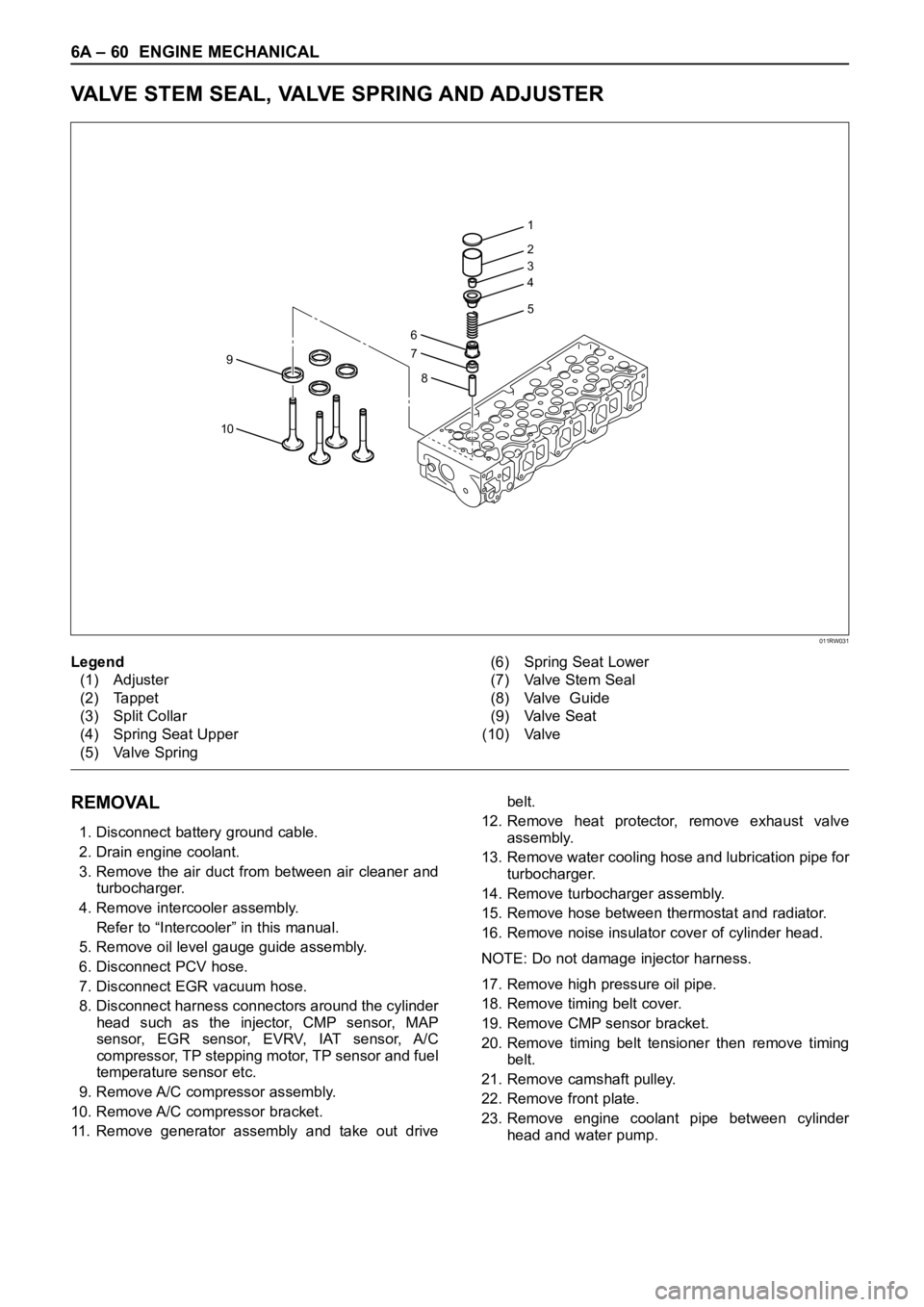
Legend
(1) Adjuster
(2) Tappet
(3) Split Collar
(4) Spring Seat Upper
(5) Valve Spring(6) Spring Seat Lower
(7) Valve Stem Seal
(8) Valve Guide
(9) Valve Seat
(10) Valve
Page 1794 of 6000
ENGINE MECHANICAL 6A – 61
24. Remove fuel pipe between fuel pump and intake
manifold.
25. Remove fuel return pipe from rear of cylinder head.
26. Remove intake manifold assembly.
27. Disconnect glow plug harness and remove glow
plug.
28. Remove cylinder head cover.
29. Remove injector harness connector.
30. Disconnect harness connector from oil pressure
sensor and oil temperature sensor on the oil rail.
31. Remove injector harness assembly.
32. Remove injector clamp.
33. Remove injector is fixed bolts.
34. Remove injector assembly.
35. Remove oil rail.
36. Remove camshaft carrier assembly with camshaft.
37. Remove cylinder head assembly.
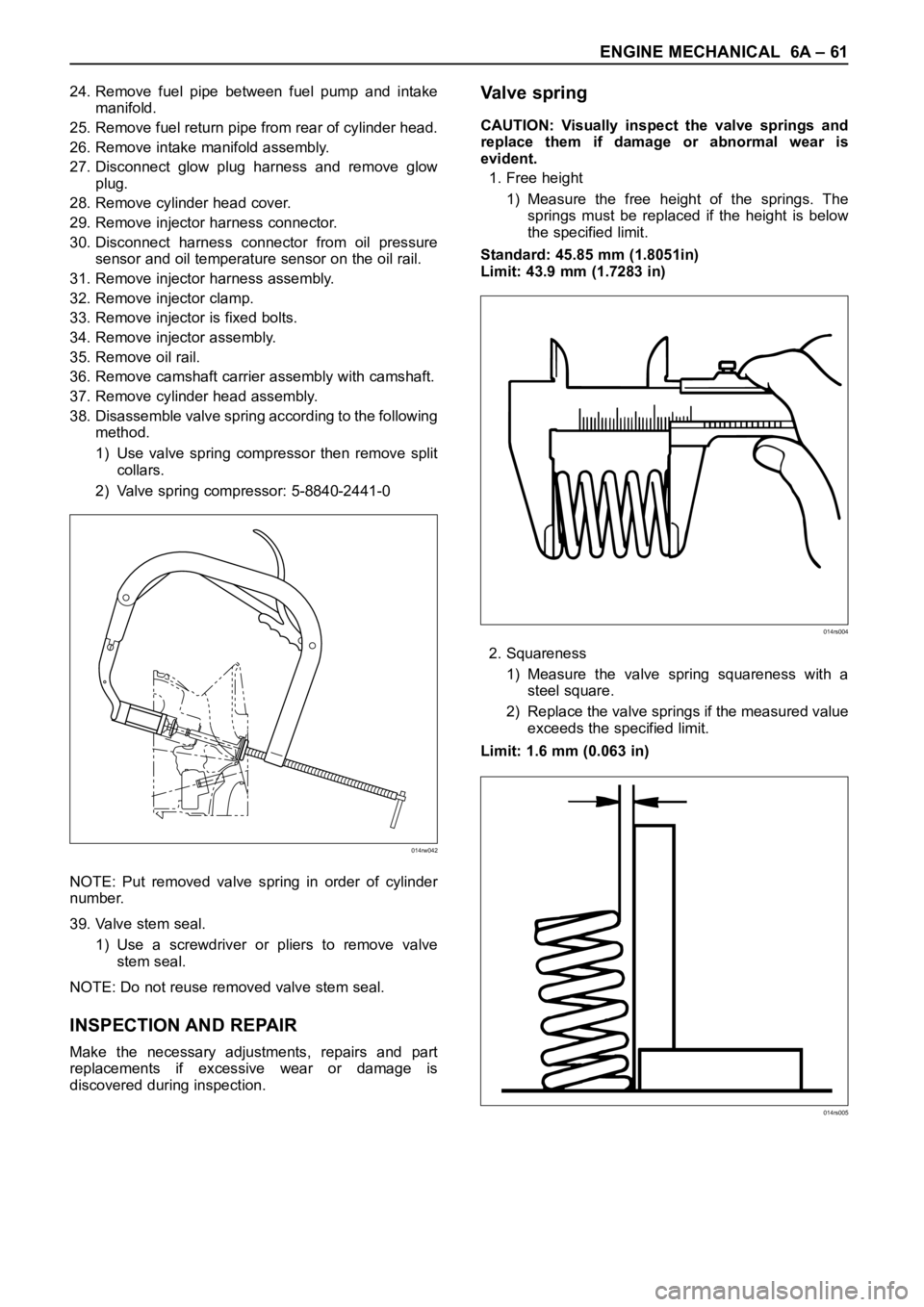
38. Disassemble valve spring according to the following
method.
1) Use valve spring compressor then remove split
collars.
2) Valve spring compressor: 5-8840-2441-0
NOTE: Put removed valve spring in order of cylinder
number.
39. Valve stem seal.
1) Use a screwdriver or pliers to remove valve
stem seal.
NOTE: Do not reuse removed valve stem seal.
INSPECTION AND REPAIR
Make the necessary adjustments, repairs and part
replacements if excessive wear or damage is
discovered during inspection.
Va l v e s p r i n g
CAUTION: Visually inspect the valve springs and
replace them if damage or abnormal wear is
evident.
1. Free height
1) Measure the free height of the springs. The
springs must be replaced if the height is below
the specified limit.
Standard: 45.85 mm (1.8051in)
Limit: 43.9 mm (1.7283 in)
2. Squareness
1) Measure the valve spring squareness with a
steel square.
2) Replace the valve springs if the measured value
exceeds the specified limit.
Limit: 1.6 mm (0.063 in)
014rw042
014rs004
014rs005
Page 1799 of 6000
6A – 66 ENGINE MECHANICAL
INSTALLATION
1. Valve stem seal
1) Use the special tool to install the stem seal to the
valve guide.
Stem Seal Installer: 5-8840-2033-0
2. Valve spring.
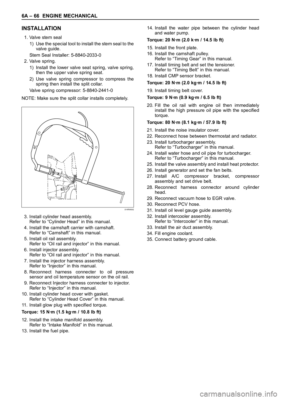
1) Install the lower valve seat spring, valve spring,
then the upper valve spring seat.
2) Use valve spring compressor to compress the
spring then install the split collar.
Valve spring compressor: 5-8840-2441-0
NOTE: Make sure the split collar installs completely.
3. Install cylinder head assembly.
Refer to “Cylinder Head” in this manual.
4. Install the camshaft carrier with camshaft.
Refer to “Camshaft” in this manual.
5. Install oil rail assembly.
Refer to “Oil rail and injector” in this manual.
6. Install injector assembly.
Refer to “Oil rail and injector” in this manual.
7. Install the injector harness assembly.
Refer to “Injector” in this manual.
8. Reconnect harness connecter to oil pressure
sensor and oil temperature sensor on the oil rail.
9. Reconnect Injector harness connecter to injector.
Refer to “Injector” in this manual.
10. Install cylinder head cover with gasket.
Refer to “Cylinder Head Cover” in this manual.
11. Install glow plug with specified torque.
Torque: 15 Nꞏm (1.5 kgꞏm / 10.8 lb ft)
12. Install the intake manifold assembly.
Refer to “Intake Manifold” in this manual.
13. Install the fuel pipe.14. Install the water pipe between the cylinder head
and water pump.
Torque: 20 Nꞏm (2.0 kꞏm / 14.5 lb ft)
15. Install the front plate.
16. Install the camshaft pulley.
Refer to “Timing Gear” in this manual.
17. Install timing belt and set the tensioner.
Refer to “Timing Belt” in this manual.
18. Install CMP sensor bracket.
Torque: 20 Nꞏm (2.0 kgꞏm / 14.5 lb ft)
19. Install timing belt cover.
Torque: 9 Nꞏm (0.9 kgꞏm / 6.5 lb ft)
20. Fill the oil rail with engine oil then immediately
install the high pressure oil pipe with the specified
torque.
Torque: 80 Nꞏm (8.1 kgꞏm / 57.9 lb ft)
21. Install the noise insulator cover.
22. Reconnect hose between thermostat and radiator.
23. Install turbocharger assembly.
Refer to “Turbocharger” in this manual.
24. Install water hose and oil pipe for turbocharger.
Refer to “Turbocharger” in this manual.
25. Install the valve assembly and install heat protector.
26. Install generator and set the fan belts.
27. Install A/C compressor bracket, compressor
assembly and set drive belt.
28. Reconnect harness connector around cylinder
head.
29. Reconnect vacuum hose to EGR valve.
30. Reconnect PCV hose.
31. Install oil level gauge guide assembly.
32. Install intercooler assembly.
Refer to “Intercooler” in this manual.
33. Install the air duct assembly.
34. Fill engine coolant.
35. Connect battery ground cable.
014RW042