1998 OPEL FRONTERA check oil
[x] Cancel search: check oilPage 2181 of 6000
7A–27 AUTOMATIC TRANSMISSION (4L30–E)
Changing Transmission Fluid
There is no need to change the transmission fluid unless
the transmission is used under one or more of the
following heavy duty conditions.
A. Repeated short trips
B. Driving on rough roads
C. Driving on dusty roads
D. Towing a trailer
If the vehicle is used under these conditions, change the
fluid every 20,000 miles (32,000 km.)
More over, the remaining life percentage of ATF can be
estimated by using Tech 2 as an auxiliary tool to judge the
right time for ATF replacement.
The remaining life percentage is calculated from ATF’S
heat history. When it is close to 0%, ATF replacement is
recommended.
1. Place a large drain pan under the oil pan.
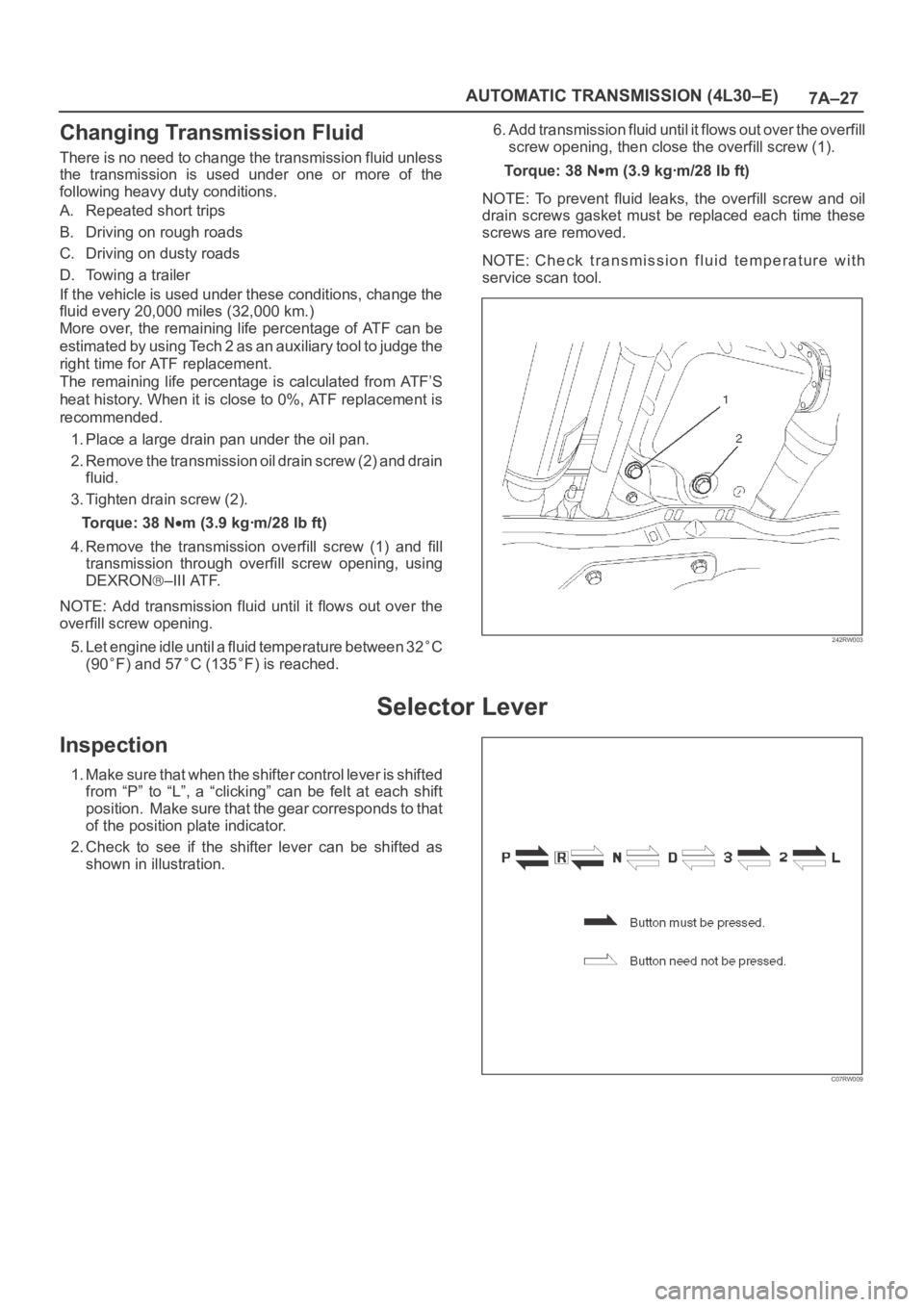
2. Remove the transmission oil drain screw (2) and drain
fluid.
3. Tighten drain screw (2).
Torque: 38 N
m (3.9 kgꞏm/28 lb ft)
4. Remove the transmission overfill screw (1) and fill
transmission through overfill screw opening, using
DEXRON
–III ATF.
NOTE: Add transmission fluid until it flows out over the
overfill screw opening.
5. Let engine idle until a fluid temperature between 32
C
(90
F) and 57C (135F) is reached.6. Add transmission fluid until it flows out over the overfill
screw opening, then close the overfill screw (1).
To r q u e : 3 8 N
m (3.9 kgꞏm/28 lb ft)
NOTE: To prevent fluid leaks, the overfill screw and oil
drain screws gasket must be replaced each time these
screws are removed.
NOTE: Check transmission fluid temperature with
service scan tool.
242RW003
Selector Lever
Inspection
1. Make sure that when the shifter control lever is shifted
from “P” to “L”, a “clicking” can be felt at each shift
position. Make sure that the gear corresponds to that
of the position plate indicator.
2. Check to see if the shifter lever can be shifted as
shown in illustration.
C07RW009
Page 2192 of 6000
7A–38
AUTOMATIC TRANSMISSION (4L30–E)
Valve Body Assembly (Main Case)
Removal
1. Raise the vehicle and support it on jack stands.
2. Disconnect battery ground cable.
3. Remove transfer and exhaust protectors.
4. Drain fluid.
5. Remove exhaust pipe and disconnect oxygen sensor
connector.
6. Support transfer case with a jack and remove third
crossmember.
7. Remove sixteen 10 mm screws, main case oil pan,
magnet and gasket.
8. Remove three 13 mm oil filter fixing screws, then
remove oil filter.
9. Remove two 13 mm manual detent fixing screws,
then remove roller and spring assembly.
10. Disconnect wiring harness from band control
solenoid and shift solenoids. Pull only on connectors,
not on wiring harness.
11. Remove four 13 mm servo cover fixing screws, then
remove servo cover and gasket.
12. Remove seven 13 mm valve body fixing screws.
Disconnect the ground wire from the main case
valve body.
13. Remove main case valve body with manual valve link
and transfer plate. Note the position of the link (long
end into valve, short end into range selector lever).
14. Remove transfer plate gasket from main case.
15. Remove two check balls from main case.
Installation
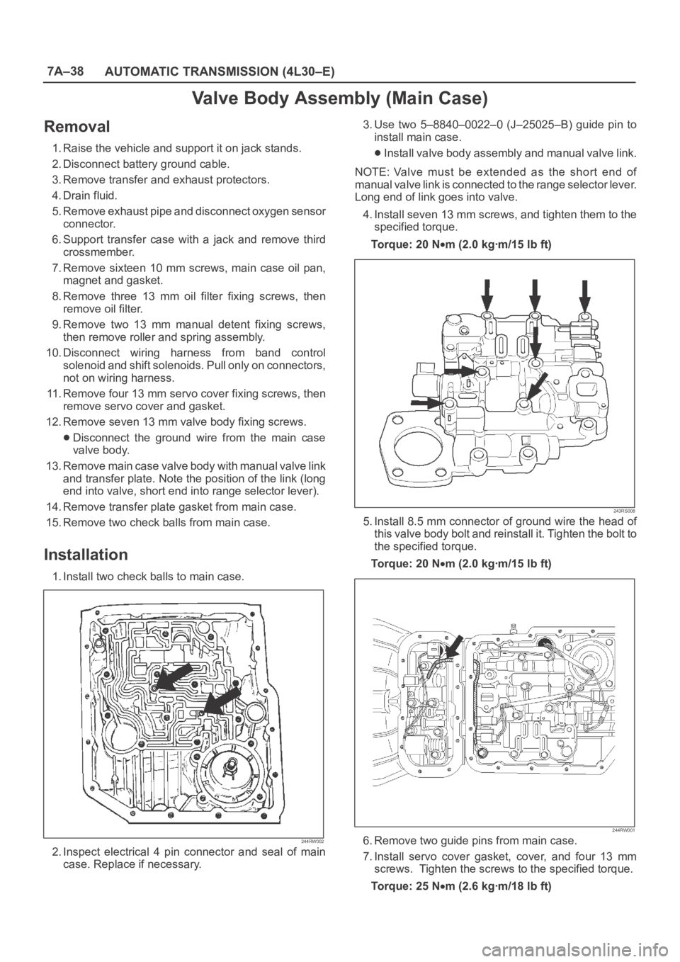
1. Install two check balls to main case.
244RW002
2. Inspect electrical 4 pin connector and seal of main
case. Replace if necessary.3. Use two 5–8840–0022–0 (J–25025–B) guide pin to
install main case.
Install valve body assembly and manual valve link.
NOTE: Valve must be extended as the short end of
manual valve link is connected to the range selector lever.
Long end of link goes into valve.
4. Install seven 13 mm screws, and tighten them to the
specified torque.
To r q u e : 2 0 N
m (2.0 kgꞏm/15 lb ft)
243RS008
5. Install 8.5 mm connector of ground wire the head of
this valve body bolt and reinstall it. Tighten the bolt to
the specified torque.
To r q u e : 2 0 N
m (2.0 kgꞏm/15 lb ft)
244RW001
6. Remove two guide pins from main case.
7. Install servo cover gasket, cover, and four 13 mm
screws. Tighten the screws to the specified torque.
To r q u e : 2 5 N
m (2.6 kgꞏm/18 lb ft)
Page 2198 of 6000
7A–44
AUTOMATIC TRANSMISSION (4L30–E)
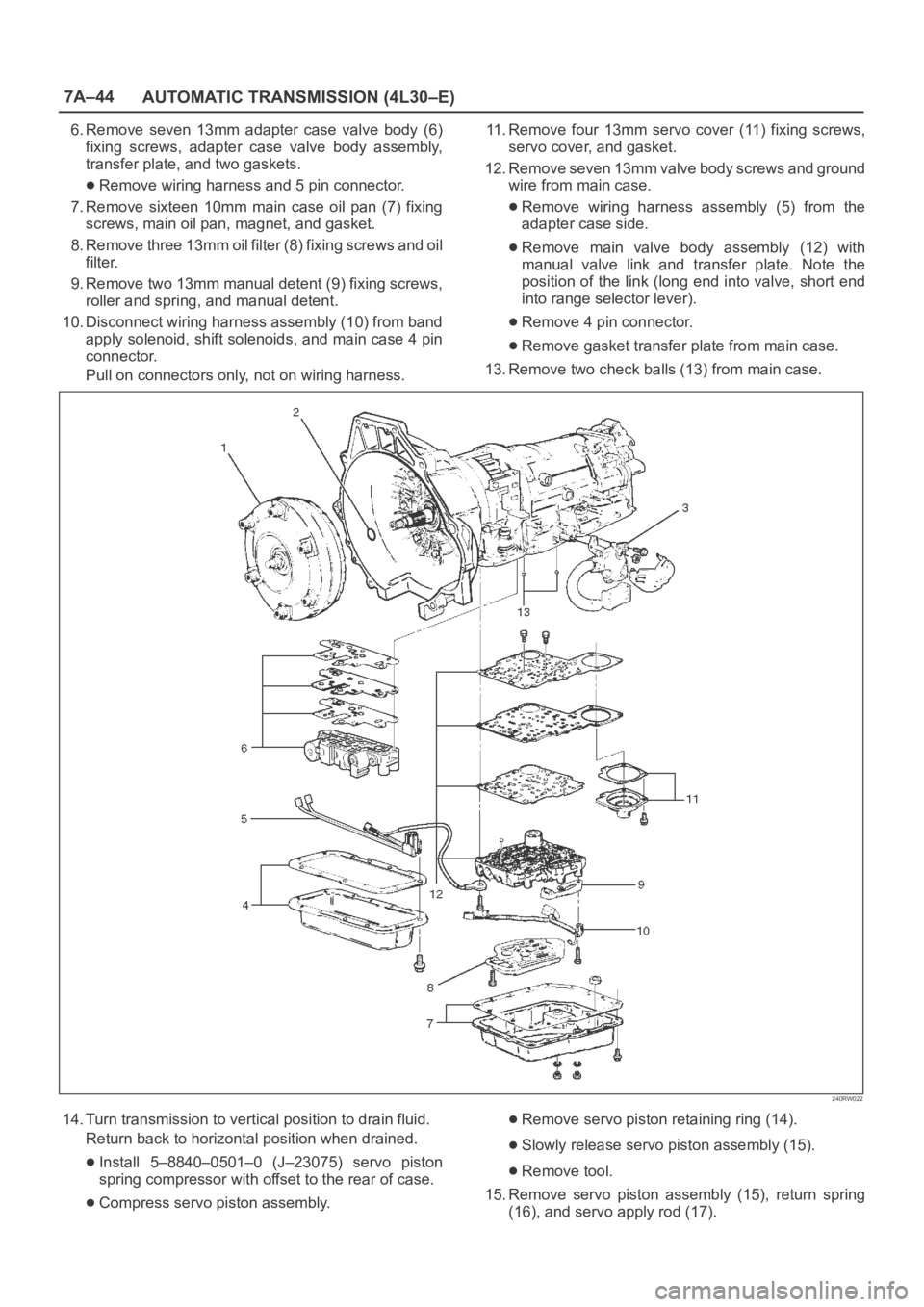
6. Remove seven 13mm adapter case valve body (6)
fixing screws, adapter case valve body assembly,
transfer plate, and two gaskets.
Remove wiring harness and 5 pin connector.
7. Remove sixteen 10mm main case oil pan (7) fixing
screws, main oil pan, magnet, and gasket.
8. Remove three 13mm oil filter (8) fixing screws and oil
filter.
9. Remove two 13mm manual detent (9) fixing screws,
roller and spring, and manual detent.
10. Disconnect wiring harness assembly (10) from band
apply solenoid, shift solenoids, and main case 4 pin
connector.
Pull on connectors only, not on wiring harness.11. Remove four 13mm servo cover (11) fixing screws,
servo cover, and gasket.
12. Remove seven 13mm valve body screws and ground
wire from main case.
Remove wiring harness assembly (5) from the
adapter case side.
Remove main valve body assembly (12) with
manual valve link and transfer plate. Note the
position of the link (long end into valve, short end
into range selector lever).
Remove 4 pin connector.
Remove gasket transfer plate from main case.
13. Remove two check balls (13) from main case.
240RW022
14. Turn transmission to vertical position to drain fluid.
Return back to horizontal position when drained.
Install 5–8840–0501–0 (J–23075) servo piston
spring compressor with offset to the rear of case.
Compress servo piston assembly.
Remove servo piston retaining ring (14).
Slowly release servo piston assembly (15).
Remove tool.
15. Remove servo piston assembly (15), return spring
(16), and servo apply rod (17).
Page 2207 of 6000
7A–53 AUTOMATIC TRANSMISSION (4L30–E)
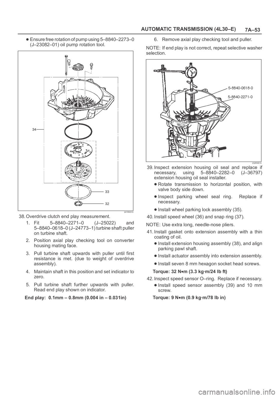
Ensure free rotation of pump using 5–8840–2273–0
(J–23082–01) oil pump rotation tool.
241RW010
38. Overdrive clutch end play measurement.
1. Fit 5–8840–2271–0 (J–25022) and
5–8840–0618–0 (J–24773–1) turbine shaft puller
on turbine shaft.
2. Position axial play checking tool on converter
housing mating face.
3. Pull turbine shaft upwards with puller until first
resistance is met. (due to weight of overdrive
assembly).
4. Maintain shaft in this position and set indicator to
zero.
5. Pull turbine shaft further upwards with puller.
Read end play shown on indicator.
End play: 0.1mm – 0.8mm (0.004 in – 0.031in)6. Remove axial play checking tool and puller.
NOTE: If end play is not correct, repeat selective washer
selection.
252RW010
39. Inspect extension housing oil seal and replace if
necessary, using 5–8840–2282–0 (J–36797)
extension housing oil seal installer.
Rotate transmission to horizontal position, with
valve body side down.
Inspect parking wheel seal ring. Replace if
necessary.
Install wheel parking lock assembly (35).
40. Install speed wheel (36) and snap ring (37).
NOTE: Use extra long, needle-nose pliers.
41. Install gasket onto extension assembly with a thin
coating of oil.
Install extension housing assembly (38), and align
parking pawl shaft.
Install actuator assembly into extension assembly.
Install seven 8 mm hexagon socket head screws.
To r q u e : 3 2 N
m (3.3 kgꞏm/24 lb ft)
42. Inspect speed sensor O–ring. Replace if necessary.
Install speed sensor assembly (39) and 10 mm
screw.
To r q u e : 9 N
m (0.9 kgꞏm/78 lb in)
Page 2209 of 6000
7A–55 AUTOMATIC TRANSMISSION (4L30–E)
242RW008
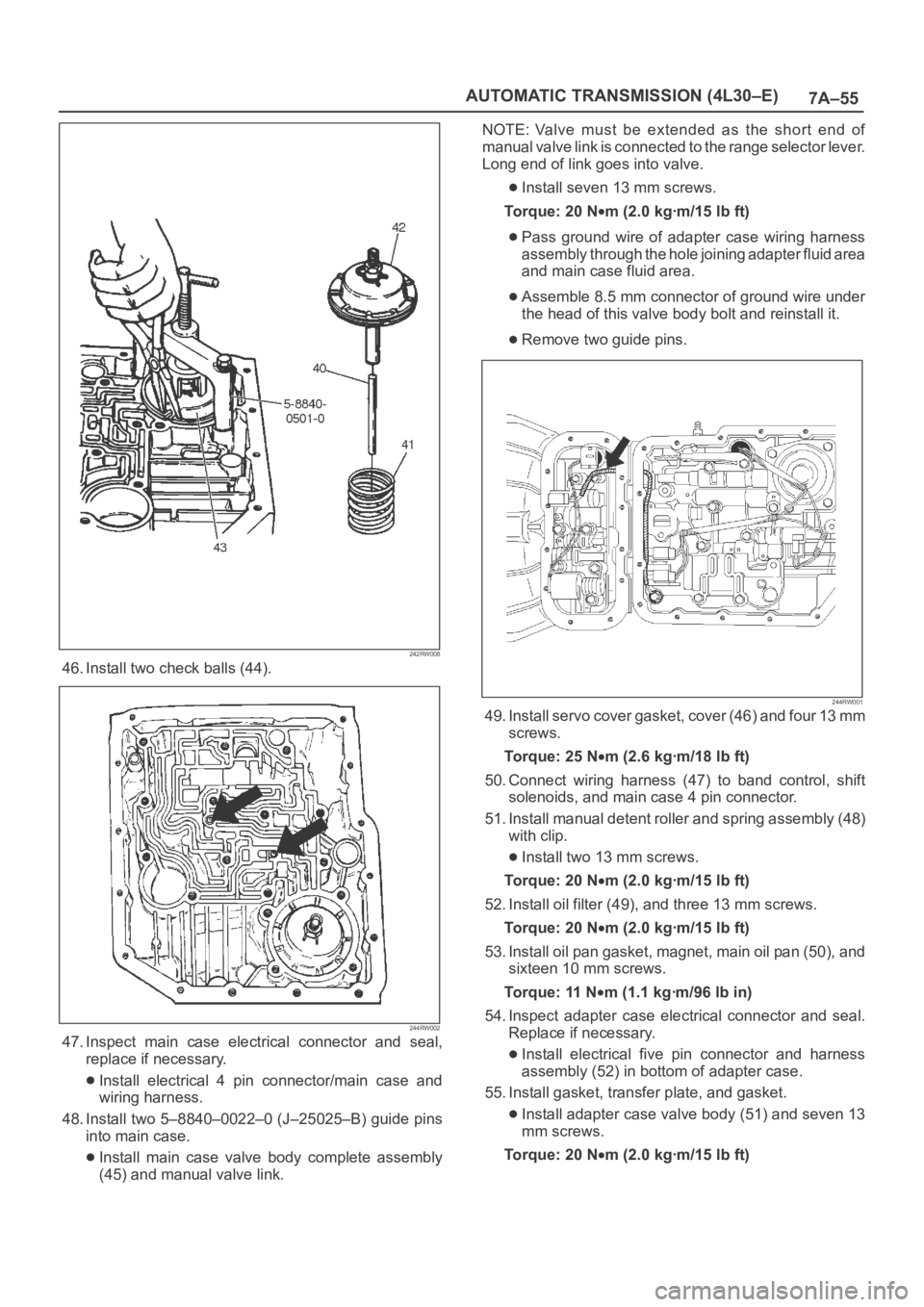
46. Install two check balls (44).
244RW002
47. Inspect main case electrical connector and seal,
replace if necessary.
Install electrical 4 pin connector/main case and
wiring harness.
48. Install two 5–8840–0022–0 (J–25025–B) guide pins
into main case.
Install main case valve body complete assembly
(45) and manual valve link.NOTE: Valve must be extended as the short end of
manual valve link is connected to the range selector lever.
Long end of link goes into valve.
Install seven 13 mm screws.
To r q u e : 2 0 N
m (2.0 kgꞏm/15 lb ft)
Pass ground wire of adapter case wiring harness
assembly through the hole joining adapter fluid area
and main case fluid area.
Assemble 8.5 mm connector of ground wire under
the head of this valve body bolt and reinstall it.
Remove two guide pins.
244RW001
49. Install servo cover gasket, cover (46) and four 13 mm
screws.
To r q u e : 2 5 N
m (2.6 kgꞏm/18 lb ft)
50. Connect wiring harness (47) to band control, shift
solenoids, and main case 4 pin connector.
51. Install manual detent roller and spring assembly (48)
with clip.
Install two 13 mm screws.
To r q u e : 2 0 N
m (2.0 kgꞏm/15 lb ft)
52. Install oil filter (49), and three 13 mm screws.
To r q u e : 2 0 N
m (2.0 kgꞏm/15 lb ft)
53. Install oil pan gasket, magnet, main oil pan (50), and
sixteen 10 mm screws.
To r q u e : 11 N
m (1.1 kgꞏm/96 lb in)
54. Inspect adapter case electrical connector and seal.
Replace if necessary.
Install electrical five pin connector and harness
assembly (52) in bottom of adapter case.
55. Install gasket, transfer plate, and gasket.
Install adapter case valve body (51) and seven 13
mm screws.
Torque: 20 N
m (2.0 kgꞏm/15 lb ft)
Page 2211 of 6000
7A–57 AUTOMATIC TRANSMISSION (4L30–E)
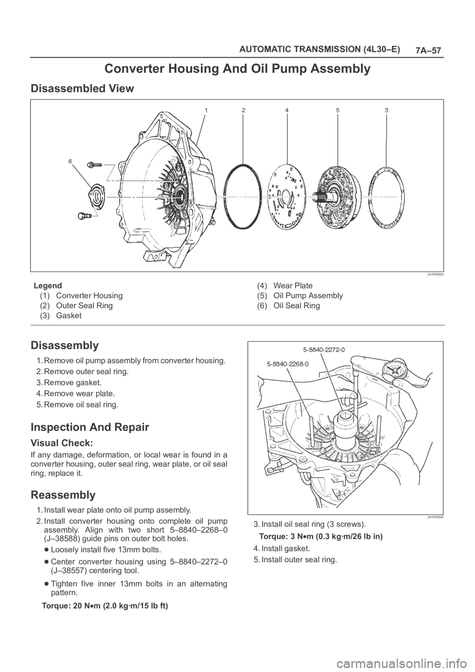
Converter Housing And Oil Pump Assembly
Disassembled View
241RW003
Legend
(1) Converter Housing
(2) Outer Seal Ring
(3) Gasket(4) Wear Plate
(5) Oil Pump Assembly
(6) Oil Seal Ring
Disassembly
1. Remove oil pump assembly from converter housing.
2. Remove outer seal ring.
3. Remove gasket.
4. Remove wear plate.
5. Remove oil seal ring.
Inspection And Repair
Visual Check:
If any damage, deformation, or local wear is found in a
converter housing, outer seal ring, wear plate, or oil seal
ring, replace it.
Reassembly
1. Install wear plate onto oil pump assembly.
2. Install converter housing onto complete oil pump
assembly. Align with two short 5–8840–2268–0
(J–38588) guide pins on outer bolt holes.
Loosely install five 13mm bolts.
Center converter housing using 5–8840–2272–0
(J–38557) centering tool.
Tighten five inner 13mm bolts in an alternating
pattern.
Torque: 20 N
m (2.0 kgꞏm/15 lb ft)
241RW020
3. Install oil seal ring (3 screws).
To r q u e : 3 N
m (0.3 kgꞏm/26 lb in)
4. Install gasket.
5. Install outer seal ring.
Page 2212 of 6000
7A–58
AUTOMATIC TRANSMISSION (4L30–E)
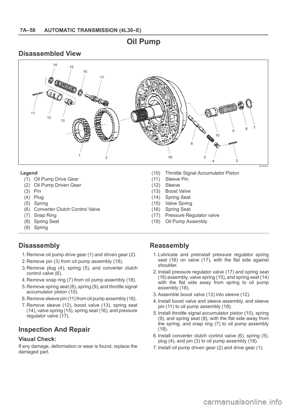
Oil Pump
Disassembled View
241RS014
Legend
(1) Oil Pump Drive Gear
(2) Oil Pump Driven Gear
(3) Pin
(4) Plug
(5) Spring
(6) Converter Clutch Control Valve
(7) Snap Ring
(8) Spring Seat
(9) Spring(10) Throttle Signal Accumulator Piston
(11) Sleeve Pin
(12) Sleeve
(13) Boost Valve
(14) Spring Seat
(15) Valve Spring
(16) Spring Seat
(17) Pressure Regulator valve
(18) Oil Pump Assembly
Disassembly
1. Remove oil pump drive gear (1) and driven gear (2).
2. Remove pin (3) from oil pump assembly (18).
3. Remove plug (4), spring (5), and converter clutch
control valve (6).
4. Remove snap ring (7) from oil pump assembly (18).
5. Remove spring seat (8), spring (9), and throttle signal
accumulator piston (10).
6. Remove sleeve pin (11) from oil pump assembly (18).
7. Remove sleeve (12), boost valve (13), spring seat
(14), valve spring (15), spring seat (16), and pressure
regulator valve (17).
Inspection And Repair
Visual Check:
If any damage, deformation or wear is found, replace the
damaged part.
Reassembly
1. Lubricate and preinstall pressure regulator spring
seat (16) on valve (17), with the flat side against
shoulder.
2. Install pressure regulator valve (17) and spring seat
(16) assembly, valve spring (15), and spring seat (14)
with the flat side away from spring to oil pump
assembly (18).
3. Assemble boost valve (13) into sleeve (12).
4. Install boost valve and sleeve assembly, and sleeve
pin (11) to oil pump assembly (18).
5. Install throttle signal accumulator piston (10), spring
(9), and spring seat (8), with the flat side away from
the spring, and snap ring (7) to oil pump assembly
(18).
6. Install converter clutch control valve (6), spring (5),
plug (4), and pin (3) to oil pump assembly (18).
7. Install oil pump driven gear (2) and drive gear (1).
Page 2214 of 6000
7A–60
AUTOMATIC TRANSMISSION (4L30–E)
10. Remove retainer (13), 2–3 shift valve (14), and spring
(15).
11. Remove spring pin (16), plug (17), spring (18), and
low pressure control valve (19).
12. Remove spring pin (20), plug (21), and band control
screen assembly (22).
13. Remove spring pin (23), plug (24), 1–2 accumulator
valve (25), and 1–2 accumulator control valve (26).
14. Remove check ball (27) from valve body (28).
Inspection And Repair
Inspect for the following, and replace any damaged or
worn parts:
1. Damage or wear to each valve.
2. Damage in oil passeges.
3. Cracks or damage to valve body.
4. Valve operations.
5. Spring fatigue.
Reassembly
1. Install 1–2 accumulator control valve (26), 1–2
accumulator valve (25), plug (24), and spring pin (23).
2. Install band control screen assembly (22), plug (21),
and spring pin (20).
3. Install low pressure control valve (19), spring (18),
plug (17), and spring pin (16).
4. Install spring (15), 2–3 shift valve (14), retainer (13),
solenoid B (12), and spring pin (11).
5. Install spring (10), 1–2/3–4 shift valve (9), retainer (8),
solenoid A (7), and spring pin (6).
6. Install waved washer (5), band control solenoid (3),
and pin (4).
7. Install manual valve (2).
8. Install check ball (27) to valve body (28).
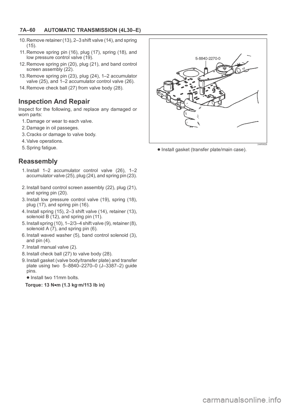
9. Install gasket (valve body/transfer plate) and transfer
plate using two 5–8840–2270–0 (J–3387–2) guide
pins.
Install two 11mm bolts.
Torque: 13 N
m (1.3 kgꞏm/113 lb in)
244RW004
Install gasket (transfer plate/main case).