Page 3362 of 6000
SECURITY AND LOCKS8H–23
5. Remove the instrument panel cluster assembly(4).
Refer to the Instrument Panel Assembly in Body
Structure section.
6. Remove two screws and then remove the anti-theft
indicator(5).
821RW032
Anti-theft Indicator Installation
To install, follow the removal steps in the reverse order.
Anti-theft Horn Removal
1. Disconnect the battery ground cable.
2. Disconnect the connector and remove the fixing bolt
to remove the anti-theft horn(1).
828RS007
Anti-Theft Horn Installation
To install, follow the removal steps in the reverse order.
Engine Hood Switch Removal
1. Disconnect the battery ground cable.
2. Remove the cap(1).
3. Remove the lock nut(2).
4. Disconnect the connector(4).
5. Remove the engine hood switch(3).
828RS011
Engine Hood Switch Installation
To install, follow the removal steps in the reverse order.
Page 3363 of 6000

8H–24SECURITY AND LOCKS
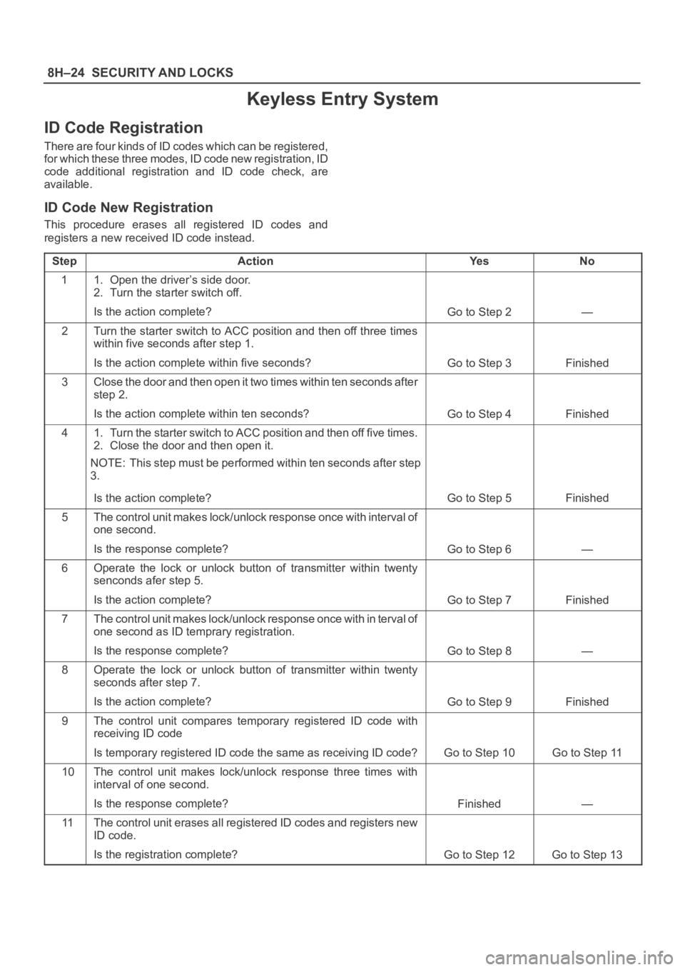
Keyless Entry System
ID Code Registration
There are four kinds of ID codes which can be registered,
for which these three modes, ID code new registration, ID
code additional registration and ID code check, are
available.
ID Code New Registration
This procedure erases all registered ID codes and
registers a new received ID code instead.
Step
ActionYe sNo
11. Open the driver’s side door.
2. Turn the starter switch off.
Is the action complete?
Go to Step 2—
2Turn the starter switch to ACC position and then off three times
within five seconds after step 1.
Is the action complete within five seconds?
Go to Step 3Finished
3Close the door and then open it two times within ten seconds after
step 2.
Is the action complete within ten seconds?
Go to Step 4Finished
41. Turn the starter switch to ACC position and then off five times.
2. Close the door and then open it.
NOTE: This step must be performed within ten seconds after step
3.
Is the action complete?
Go to Step 5Finished
5The control unit makes lock/unlock response once with interval of
one second.
Is the response complete?
Go to Step 6—
6Operate the lock or unlock button of transmitter within twenty
senconds afer step 5.
Is the action complete?
Go to Step 7Finished
7The control unit makes lock/unlock response once with in terval o f
one second as ID temprary registration.
Is the response complete?
Go to Step 8—
8Operate the lock or unlock button of transmitter within twenty
seconds after step 7.
Is the action complete?
Go to Step 9Finished
9The control unit compares temporary registered ID code with
receiving ID code
Is temporary registered ID code the same as receiving ID code?
Go to Step 10Go to Step 11
10The control unit makes lock/unlock response three times with
interval of one second.
Is the response complete?
Finished—
11The control unit erases all registered ID codes and registers new
ID code.
Is the registration complete?
Go to Step 12Go to Step 13
Page 3364 of 6000

SECURITY AND LOCKS8H–25
StepNo Ye s Action
12The control unit makes lock/unlock response once with interval of
one second.
Is the response complete?
Finished—
13The control unit makes lock/unlock response three times with
interval of one second.
Is the response complete?
Finished—
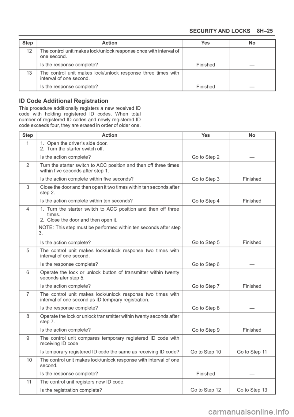
ID Code Additional Registration
This procedure additionally registers a new received ID
code with holding registered ID codes. When total
number of registered ID codes and newly registered ID
code exceeds four, they are erased in order of older one.
Step
ActionYe sNo
11. Open the driver’s side door.
2. Turn the starter switch off.
Is the action complete?
Go to Step 2—
2Turn the starter switch to ACC position and then off three times
within five seconds after step 1.
Is the action complete within five seconds?
Go to Step 3Finished
3Close the door and then open it two times within ten seconds after
step 2.
Is the action complete within ten seconds?
Go to Step 4Finished
41. Turn the starter switch to ACC position and then off three
times.
2. Close the door and then open it.
NOTE: This step must be performed within ten seconds after step
3.
Is the action complete?
Go to Step 5Finished
5The control unit makes lock/unlock response two times with
interval of one second.
Is the response complete?
Go to Step 6—
6Operate the lock or unlock button of transmitter within twenty
seconds afer step 5.
Is the action complete?
Go to Step 7Finished
7The control unit makes lock/unlock response two times with
interval of one second as ID temprary registration.
Is the response complete?
Go to Step 8—
8Operate the lock or unlock transmitter within twenty seconds after
step 7.
Is the action complete?
Go to Step 9Finished
9The control unit compares temporary registered ID code with
receiving ID code
Is temporary registered ID code the same as receiving ID code?
Go to Step 10Go to Step 11
10The control unit makes lock/unlock response with interval of one
second.
Is the response complete?
Finished—
11The control unit registers new ID code.
Is the registration complete?
Go to Step 12Go to Step 13
Page 3365 of 6000

8H–26SECURITY AND LOCKS
StepNo Ye s Action
12The control unit makes lock/unlock response once with interval of
one second.
Is the response complete?
Finished—
13The control unit makes lock/unlock response three times with
interval of one second.
Is the response complete?
Finished—
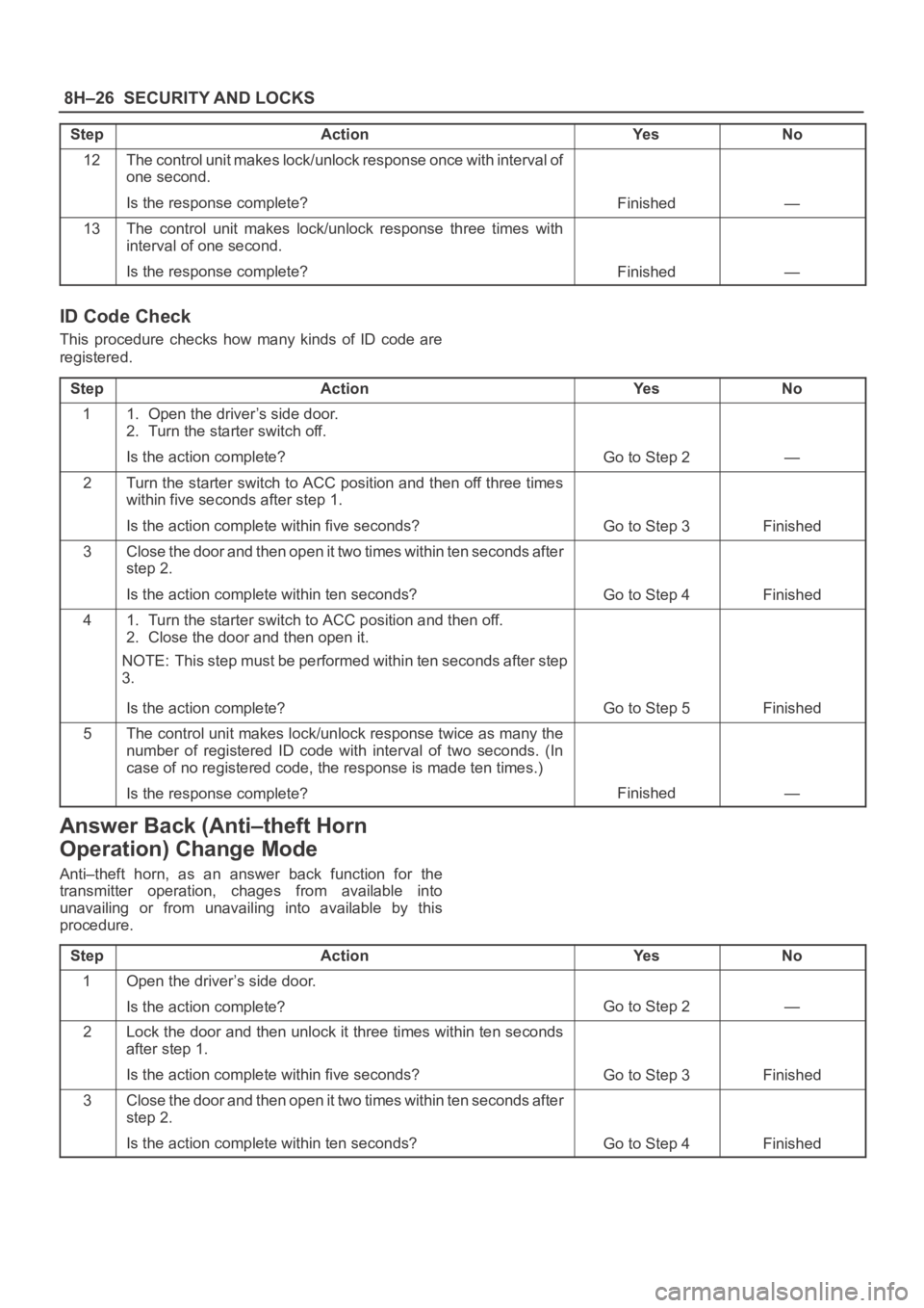
ID Code Check
This procedure checks how many kinds of ID code are
registered.
Step
ActionYe sNo
11. Open the driver’s side door.
2. Turn the starter switch off.
Is the action complete?
Go to Step 2—
2Turn the starter switch to ACC position and then off three times
within five seconds after step 1.
Is the action complete within five seconds?
Go to Step 3Finished
3Close the door and then open it two times within ten seconds after
step 2.
Is the action complete within ten seconds?
Go to Step 4Finished
41. Turn the starter switch to ACC position and then off.
2. Close the door and then open it.
NOTE: This step must be performed within ten seconds after step
3.
Is the action complete?
Go to Step 5Finished
5The control unit makes lock/unlock response twice as many the
number of registered ID code with interval of two seconds. (In
case of no registered code, the response is made ten times.)
Is the response complete?
Finished—
Answer Back (Anti–theft Horn
Operation) Change Mode
Anti–theft horn, as an answer back function for the
transmitter operation, chages from available into
unavailing or from unavailing into available by this
procedure.
Step
ActionYe sNo
1Open the driver’s side door.
Is the action complete?
Go to Step 2—
2Lock the door and then unlock it three times within ten seconds
after step 1.
Is the action complete within five seconds?
Go to Step 3Finished
3Close the door and then open it two times within ten seconds after
step 2.
Is the action complete within ten seconds?
Go to Step 4Finished
Page 3366 of 6000

SECURITY AND LOCKS8H–27
StepNo Ye s Action
41. Lock the door and unlock it three times.
2. Close the door and then open it.
NOTE: This step must be performed within ten seconds after step
3.
Is the action complete?
Go to Step 5Finished
5Answer back mode changes.
Is this step complete?
Go to Step 6Go to Step 7
6The control unit makes lock/unlock response once with interval of
one second.
Is the response complete?
Finished—
7The control unit makes lock/unlock response three times with
interval of one second.
Is the response complete?
Finished—
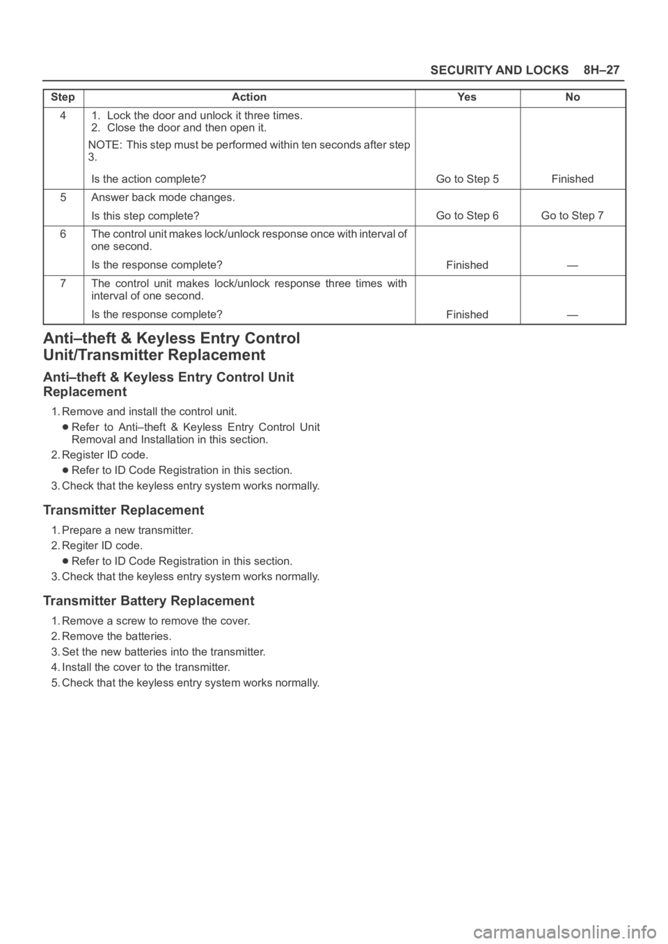
Anti–theft & Keyless Entry Control
Unit/Transmitter Replacement
Anti–theft & Keyless Entry Control Unit
Replacement
1. Remove and install the control unit.
Refer to Anti–theft & Keyless Entry Control Unit
Removal and Installation in this section.
2. Register ID code.
Refer to ID Code Registration in this section.
3. Check that the keyless entry system works normally.
Transmitter Replacement
1. Prepare a new transmitter.
2. Regiter ID code.
Refer to ID Code Registration in this section.
3. Check that the keyless entry system works normally.
Transmitter Battery Replacement
1. Remove a screw to remove the cover.
2. Remove the batteries.
3. Set the new batteries into the transmitter.
4. Install the cover to the transmitter.
5. Check that the keyless entry system works normally.
Page 3367 of 6000
8H–28SECURITY AND LOCKS
Main Data and Specifications
Torque Specifications
ApplicationNꞏmKgꞏmLb FtLb In
Front Door Lock Assembly Fixing Screws70.7—61
Front Outside Handle and Key Switch Fixing Bolts90.9—78
Rear Door Lock Assembly Fixing Screws70.7—61
Rear Outside Handle Fixing Bolts90.9—78
Tailgate Lock Assembly (LH) Fixing Screws70.7—61
Tailgate Lock Assembly (RH) Fixing Bolts111.1—95
Tailgate Outside Handle and Key Cylinder Fixing Bolts90.9—78
Page 3382 of 6000
EXTERIOR/INTERIOR TRIM8J–3
Dash Side Trim Panel
Removal
1. Disconnect the battery ground cable.
2. Remove the Front door sill plate(2).
3. Remove the Dash side trim panel(3).
Turn up the door inner seal(1) of the body panel to
remove the clips of the trim panel.
Take care not to damage the harness and the
controller on the back of the trim panel.
643RW005
Installation
To install, follow the removal steps in the reverse order,
noting the following point.
1. Lap the door inner seal over the trim panel to install
them securely to the body panel.
Assist Grip
Parts Location
745RW006
Legend
(1) Assist Grip
Removal and Installation
Refer to the Consoles removal and installation steps
in this section.
Page 3388 of 6000
EXTERIOR/INTERIOR TRIM8J–9
Installation
To install, follow the removal steps in the reverse order,
noting the following point.
1. When installing the inside handle(2), assemble it
temporarily to the inside handle link(1).
632RS014
2. Pass the inside handle(4) through the mounting hole
of the trim panel and assemble the trim panel.
Engage seven clips(8) into the door panel. Also,
connect the courtesy light connector(5) and leave the
connectors of the speaker(7), tweeter(9) and power
window(3) drawn out to their prescribed positions, so
that they will not be caught.
Then, put the inside handle(4) to the normal position
of the inside handle link(6).
632RW006
3. Fit the claw(10) of the inside handle(11) securely into
the hole of the door panel and fix the inside handle
with the screw.
632RW007