1998 OPEL FRONTERA steering wheel
[x] Cancel search: steering wheelPage 1004 of 6000
6A–48
ENGINE MECHANICAL
Engine Assembly
Removal
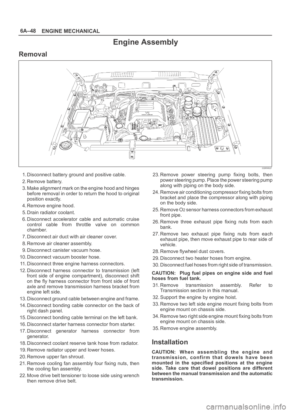
035RW027
1. Disconnect battery ground and positive cable.
2. Remove battery.
3. Make alignment mark on the engine hood and hinges
before removal in order to return the hood to original
position exactly.
4. Remove engine hood.
5. Drain radiator coolant.
6. Disconnect accelerator cable and automatic cruise
control cable from throttle valve on common
chamber.
7. Disconnect air duct with air cleaner cover.
8. Remove air cleaner assembly.
9. Disconnect canister vacuum hose.
10. Disconnect vacuum booster hose.
11. Disconnect three engine harness connectors.
12. Disconnect harness connector to transmission (left
front side of engine compartment), disconnect shift
on the fly harness connector from front side of front
axle and remove transmission harness bracket from
engine left side.
13. Disconnect ground cable between engine and frame.
14. Disconnect bonding cable connector on the back of
right dash panel.
15. Disconnect bonding cable terminal on the left bank.
16. Disconnect starter harness connector from starter.
17. Disconnect generator harness connector from
generator.
18. Disconnect coolant reserve tank hose from radiator.
19. Remove radiator upper and lower hoses.
20. Remove upper fan shroud.
21. Remove cooling fan assembly four fixing nuts, then
the cooling fan assembly.
22. Move drive belt tensioner to loose side using wrench
then remove drive belt.23. Remove power steering pump fixing bolts, then
power steering pump. Place the power steering pump
along with piping on the body side.
24. Remove air conditioning compressor fixing bolts from
bracket and place the compressor along with piping
on the body side.
25. Remove O
2 sensor harness connectors from exhaust
front pipe.
26. Remove three exhaust pipe fixing nuts from each
bank.
27. Remove two exhaust pipe fixing nuts from each
exhaust pipe, then move exhaust pipe to rear side of
vehicle.
28. Remove flywheel dust covers.
29. Disconnect two heater hoses from engine.
30. Disconnect fuel hoses from right side of transmission.
CAUTION: Plug fuel pipes on engine side and fuel
hoses from fuel tank.
31. Remove transmission assembly. Refer to
Transmission section in this manual.
32. Support the engine by engine hoist.
33. Remove two left side engine mount fixing bolts from
engine mount on chassis side.
34. Remove two right side engine mount fixing bolts from
engine mount on chassis side.
35. Remove engine assembly.
Installation
CAUTION: W h e n a s s e m b l i n g t h e e n g i n e a n d
transmission, confirm that dowels have been
mounted in the specified positions at the engine
side. Take care that dowel positions are different
between the manual transmission and the automatic
transmission.
Page 1486 of 6000
6G–7 ENGINE LUBRICATION
Oil Pan and Crankcase
Removal
1. Disconnect battery ground cable.
2. Drain engine oil.
3. Lift vehicle by supporting the frame.
4. Remove front wheels.
5. Remove oil level dipstick from level gauge tube.
6. Remove stone guard.
7. Remove radiator under fan shroud.
8. Remove suspension cross member fixing bolts, 2 pcs
each per side and remove suspension cross member.
9. Remove pitman arm and relay lever assembly, using
the 5–8840–2005–0 remover, remove pitman arm
from the steering unit and remove four fixing bolts for
relay lever assembly.
10. Remove axle housing assembly four fixing bolts from
housing isolator side and mounting bolts from wheel
side. At this time support the axle with a garage jack
and remove axle housing assembly.
11. Remove oil pan fixing bolts.
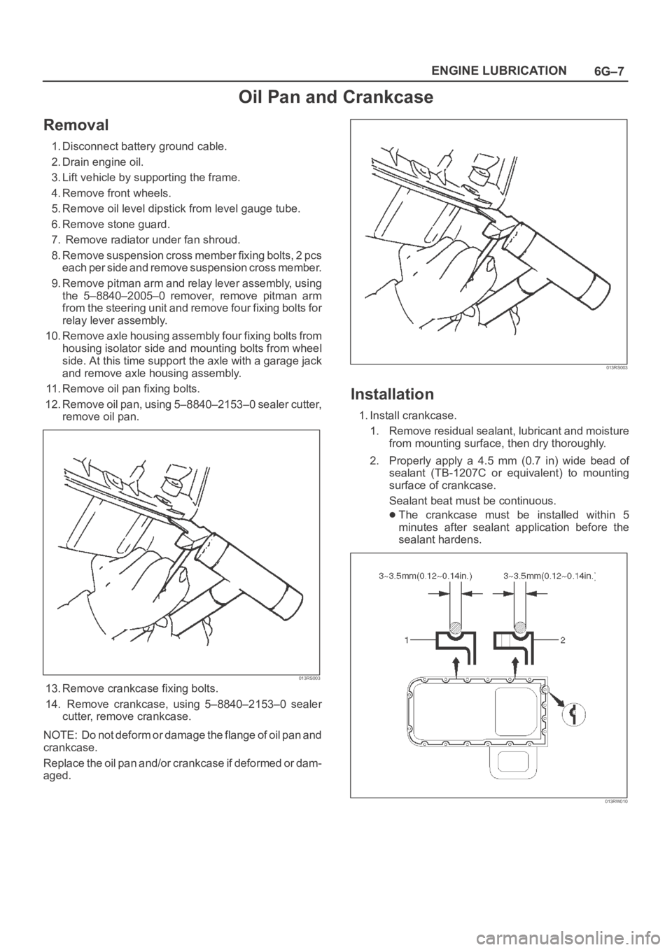
12. Remove oil pan, using 5–8840–2153–0 sealer cutter,
remove oil pan.
013RS003
13. Remove crankcase fixing bolts.
14. Remove crankcase, using 5–8840–2153–0 sealer
cutter, remove crankcase.
NOTE: Do not deform or damage the flange of oil pan and
crankcase.
Replace the oil pan and/or crankcase if deformed or dam-
aged.
013RS003
Installation
1. Install crankcase.
1. Remove residual sealant, lubricant and moisture
from mounting surface, then dry thoroughly.
2. Properly apply a 4.5 mm (0.7 in) wide bead of
sealant (TB-1207C or equivalent) to mounting
surface of crankcase.
Sealant beat must be continuous.
The crankcase must be installed within 5
minutes after sealant application before the
sealant hardens.
013RW010
Page 2557 of 6000
8A–18LIGHTING SYSTEM
Lighting Switch (Combination Switch)
Removal
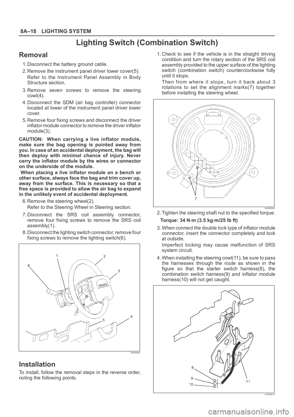
1. Disconnect the battery ground cable.
2. Remove the instrument panel driver lower cover(5).
Refer to the Instrument Panel Assembly in Body
Structure section.
3. Remove seven screws to remove the steering
cowl(4).
4. Disconnect the SDM (air bag controller) connector
located at lower of the instrument panel driver lower
cover.
5. Remove four fixing screws and disconnect the driver
inflator module connector to remove the driver inflator
module(3).
CAUTION: When carrying a live inflator module,
make sure the bag opening is pointed away from
y o u . I n c a s e o f a n a c c i d e n t a l d e p l o y m e n t , t h e b a g w i l l
then deploy with minimal chance of injury. Never
carry the inflator module by the wires or connector
on the underside of the module.
When placing a live inflator module on a bench or
other surface, always face the bag and trim cover up,
away from the surface. This is necessary so that a
free space is provided to allow the air bag to expand
in the unlikely event of accidental deployment.
6. Remove the steering wheel(2).
Refer to the Steering Wheel in Steering section.
7. Disconnect the SRS coil assembly connector,
remove four fixing screws to remove the SRS coil
assembly(1).
8. Disconnect the lighting switch connector, remove four
fixing screws to remove the lighting switch(6).
825RS039
Installation
To install, follow the removal steps in the reverse order,
noting the following points.1. Check to see if the vehicle is in the straight driving
condition and turn the rotary section of the SRS coil
assembly provided to the upper surface of the lighting
switch (combination switch) counterclockwise fully
until it stops.
Then from where it stops, turn it back about 3
rotations to set the alignment marks(7) together
before installing the steering wheel.
825RW099
2. Tighten the steering shaft nut to the specified torque.
Torque: 34 Nꞏm (3.5 kgꞏm/25 lb ft)
3. When connect the double lock type of inflator module
connector, insert the connector completely and lock
at outside.
Imperfect locking may cause malfunction of SRS
system circuit.
4. When installing the steering cowl(11), be sure to pass
the harnesses through the route as shown in the
figure so that the starter switch harness(8), the
combination switch harness(9) and inflator module
harness(10) will not get caught.
431RW014
Page 3438 of 6000
SUPPLEMENTAL RESTRAINT SYSTEM9J–1
RESTRAINTS
SUPPLEMENTAL RESTRAINT SYSTEM (SRS)
CONTENTS
Service Precaution 9J–1. . . . . . . . . . . . . . . . . . . . . .
General Description 9J–2. . . . . . . . . . . . . . . . . . . . .
SRS Component And Wiring Location View 9J–4.
Component Description 9J–4. . . . . . . . . . . . . . . . . .
Definitions 9J–7. . . . . . . . . . . . . . . . . . . . . . . . . . . . . .
Diagnosis 9J–8. . . . . . . . . . . . . . . . . . . . . . . . . . . . . .
SRS Connector Body Face Views 9J–9. . . . . . . . .
Repairs And Inspections Required After
An Accident 9J–9. . . . . . . . . . . . . . . . . . . . . . . . . . . .
On–Vehicle Service 9J–10. . . . . . . . . . . . . . . . . . . . . .
Air Bag Assembly Handling / Shipping
/ Scrapping 9J–11. . . . . . . . . . . . . . . . . . . . . . . . . . . .
Pretensioner Seat Belt Handling / Shipping
/ Scrapping. 9J–11. . . . . . . . . . . . . . . . . . . . . . . . . . . .
Special Tools 9J–26. . . . . . . . . . . . . . . . . . . . . . . . . . .
Service Precautions for SRS Component
Service 9J–30. . . . . . . . . . . . . . . . . . . . . . . . . . . . . . . .
SRS Connectors 9J–31. . . . . . . . . . . . . . . . . . . . . . . .
Sensing And Diagnostic Module (SDM) 9J–33. . . .
Service Precautions 9J–33. . . . . . . . . . . . . . . . . . .
Removal 9J–33. . . . . . . . . . . . . . . . . . . . . . . . . . . . .
Installation 9J–33. . . . . . . . . . . . . . . . . . . . . . . . . . . .
Driver Air Bag Assembly 9J–35. . . . . . . . . . . . . . . . .
Service Precautions 9J–35. . . . . . . . . . . . . . . . . . .
Removal 9J–35. . . . . . . . . . . . . . . . . . . . . . . . . . . . .
Installation 9J–36. . . . . . . . . . . . . . . . . . . . . . . . . . . .
Steering Wheel 9J–37. . . . . . . . . . . . . . . . . . . . . . . . . Service Precautions 9J–37. . . . . . . . . . . . . . . . . . .
Removal 9J–37. . . . . . . . . . . . . . . . . . . . . . . . . . . . .
Installation 9J–38. . . . . . . . . . . . . . . . . . . . . . . . . . . .
SRS Coil Assembly 9J–39. . . . . . . . . . . . . . . . . . . . . .
Service Precautions 9J–39. . . . . . . . . . . . . . . . . . .
Removal 9J–39. . . . . . . . . . . . . . . . . . . . . . . . . . . . .
Installation 9J–41. . . . . . . . . . . . . . . . . . . . . . . . . . . .
SRS Coil Replacement Procedure 9J–42. . . . . . . . .
Removal 9J–42. . . . . . . . . . . . . . . . . . . . . . . . . . . . .
How to Disconnect the horn terminal 9J–43. . . . .
How to Connect Horn Terminal 9J–43. . . . . . . . . .
Installation 9J–44. . . . . . . . . . . . . . . . . . . . . . . . . . . .
Steering Column 9J–44. . . . . . . . . . . . . . . . . . . . . . . .
Service Precautions 9J–44. . . . . . . . . . . . . . . . . . .
Removal 9J–44. . . . . . . . . . . . . . . . . . . . . . . . . . . . .
Installation 9J–46. . . . . . . . . . . . . . . . . . . . . . . . . . . .
Passenger Air Bag Assembly 9J–48. . . . . . . . . . . . .
Service Precautions 9J–48. . . . . . . . . . . . . . . . . . .
Removal 9J–48. . . . . . . . . . . . . . . . . . . . . . . . . . . . .
Installation 9J–48. . . . . . . . . . . . . . . . . . . . . . . . . . . .
Pretensioner Seat Belt (If so equipped) 9J–49. . . .
Service Precaution 9J–49. . . . . . . . . . . . . . . . . . . .
Parts Location 9J–49. . . . . . . . . . . . . . . . . . . . . . . .
Removal 9J–49. . . . . . . . . . . . . . . . . . . . . . . . . . . . .
Installation 9J–49. . . . . . . . . . . . . . . . . . . . . . . . . . . .
Main Data and Specifications 9J–50. . . . . . . . . . . . .
Service Precaution
WARNING: IF SO EQUIPPED WITH A
SUPPLEMENTAL RESTRAINT SYSTEM (SRS),
REFER TO THE SRS COMPONENT AND WIRING
LOCATION VIEW IN ORDER TO DETERMINE
WHETHER YOU ARE PERFORMING SERVICE ON OR
NEAR THE SRS COMPONENTS OR THE SRS
WIRING. WHEN YOU ARE PERFORMING SERVICE
ON OR NEAR THE SRS COMPONENTS OR THE SRS
WIRING, REFER TO THE SRS SERVICE
INFORMATION. FAILURE TO FOLLOW WARNINGS
COULD RESULT IN POSSIBLE AIR BAG
DEPLOYMENT, PERSONAL INJURY, OR
OTHERWISE UNNEEDED SRS SYSTEM REPAIRS.CAUTION: Always use the correct fastener in the
proper location. When you replace a fastener, use
ONLY the exact part number for that application.
ISUZU will call out those fasteners that require a
replacement after removal. ISUZU will also call out
the fasteners that require thread lockers or thread
sealant. UNLESS OTHERWISE SPECIFIED, do not
use supplemental coatings (Paints, greases, or other
corrosion inhibitors) on threaded fasteners or
fastener joint interfaces. Generally, such coatings
adversely affect the fastener torque and the joint
clamping force, and may damage the fastener. When
you install fasteners, use the correct tightening
sequence and specifications. Following these
instructions can help you avoid damage to parts and
systems.
Page 3439 of 6000
SUPPLEMENTAL RESTRAINT SYSTEM 9J–2
General Description
CAUTION: When fasteners are removed, always
reinstall them at the same location from which they
were removed. If a fastener needs to be replaced, use
the correct part number fastener for that application.
If the correct part number fastener is not available, a
fastener of equal size and strength (or stronger) may
be used. Fasteners that are not reused, and those
requiring thread locking compound will be called
out. The correct torque value must be used when
installing fasteners that require it. If the above
conditions are not followed, parts or system damage
could result.
Restraint Devices
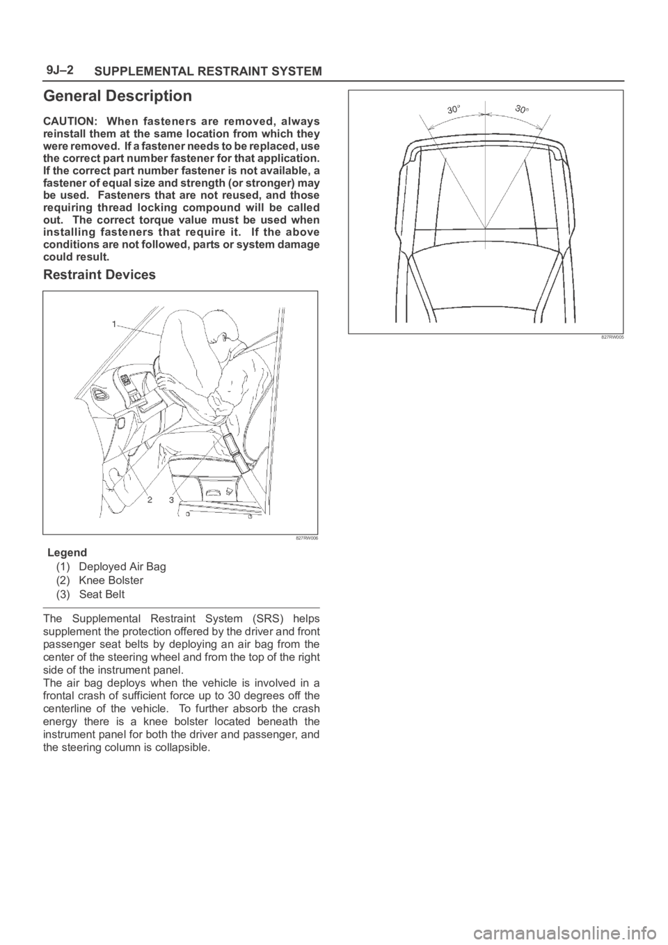
827RW006
Legend
(1) Deployed Air Bag
(2) Knee Bolster
(3) Seat Belt
The Supplemental Restraint System (SRS) helps
supplement the protection offered by the driver and front
passenger seat belts by deploying an air bag from the
center of the steering wheel and from the top of the right
side of the instrument panel.
The air bag deploys when the vehicle is involved in a
frontal crash of sufficient force up to 30 degrees off the
centerline of the vehicle. To further absorb the crash
energy there is a knee bolster located beneath the
instrument panel for both the driver and passenger, and
the steering column is collapsible.
827RW005
Page 3442 of 6000
SUPPLEMENTAL RESTRAINT SYSTEM9J–5
1. Energy Reserve — The SDM maintains 24–Volt Loop
Reserve (24VLR) energy supply to provide
deployment energy when ignition voltage is lost in a
frontal crash.
2. Frontal Crash Detection — The SDM monitors
vehicle velocity changes to detect frontal crashes
which are severe enough to warrant deployment.
3. Air Bag Deployment — When a frontal crash of
sufficient force is detected, the SDM will cause
enough current to flow through the air bag assembly
to deploy the air bag.
4. Malfunction Detection — The SDM performs
diagnostic monitoring of SRS electrical components
and sets a diagnostic trouble code when a
malfunction is detected.
5. Frontal Crash Recording — The SDM records
information regarding SRS status during frontal
crash.
6. Malfunction Diagnosis — The SDM displays SRS
diagnostic trouble codes and system status
information through the use of a scan tool.
7. Driver Notification — The SDM warns the vehicle
driver of SRS malfunctions by controlling the “Air
Bag” warning lamp.
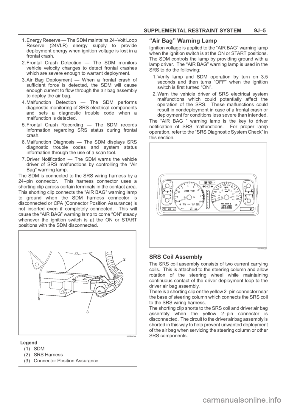
The SDM is connected to the SRS wiring harness by a
24–pin connector. This harness connector uses a
shorting clip across certain terminals in the contact area.
This shorting clip connects the “AIR BAG” warning lamp
to ground when the SDM harness connector is
disconnected or CPA (Connector Position Assurance) is
not inserted even if completely connected. This will
cause the “AIR BAG” warning lamp to come “ON” steady
whenever the ignition switch is at the ON or START
positions with the SDM disconnected.
827RW044
Legend
(1) SDM
(2) SRS Harness
(3) Connector Position Assurance
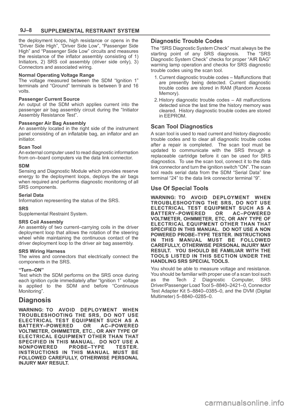
“Air Bag” Warning Lamp
Ignition voltage is applied to the “AIR BAG” warning lamp
when the ignition switch is at the ON or START positions.
The SDM controls the lamp by providing ground with a
lamp driver. The “AIR BAG” warning lamp is used in the
SRS to do the following:
1. Verify lamp and SDM operation by turn on 3.5
seconds and then turns “OFF” when the ignition
switch is first turned “ON”.
2. Warn the vehicle driver of SRS electrical system
malfunctions which could potentially affect the
operation of the SRS. These malfunctions could
result in nondeployment in case of a frontal crash or
deployment for conditions less severe than intended.
The “AIR BAG ” warning lamp is the key to driver
notification of SRS malfunctions. For proper lamp
operation, refer to the “SRS Diagnostic System Check” in
this section.
821RW037
SRS Coil Assembly
The SRS coil assembly consists of two current carrying
coils. This is attached to the steering column and allow
rotation of the steering wheel while maintaining
continuous contact of the driver deployment loop to the
driver air bag assembly.
There is a shorting clip on the yellow 2–pin connector near
the base of steering column which connects the SRS coil
to the SRS wiring harness.
The shorting clip shorts to the SRS coil and driver air bag
assembly when the yellow 2–pin connector is
disconnected. The circuit to the driver air bag assembly is
shorted in this way to help prevent unwanted deployment
of the air bag when servicing the steering column or other
SRS components.
Page 3444 of 6000
SUPPLEMENTAL RESTRAINT SYSTEM9J–7
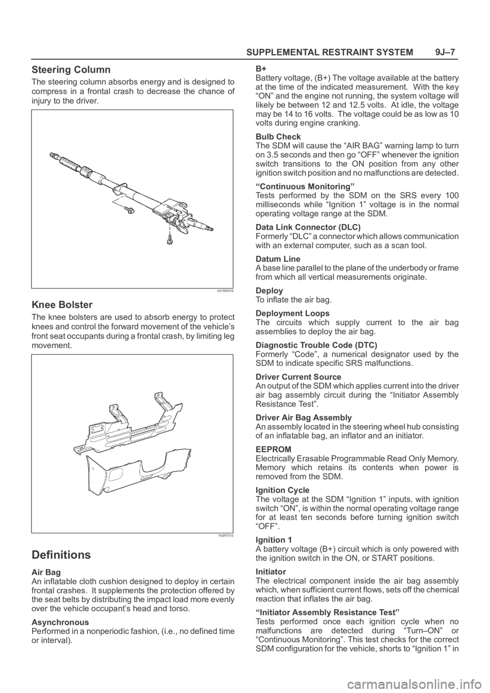
Steering Column
The steering column absorbs energy and is designed to
compress in a frontal crash to decrease the chance of
injury to the driver.
431RW019
Knee Bolster
The knee bolsters are used to absorb energy to protect
knees and control the forward movement of the vehicle’s
front seat occupants during a frontal crash, by limiting leg
movement.
740RT015
Definitions
Air Bag
An inflatable cloth cushion designed to deploy in certain
frontal crashes. It supplements the protection offered by
the seat belts by distributing the impact load more evenly
over the vehicle occupant’s head and torso.
Asynchronous
Performed in a nonperiodic fashion, (i.e., no defined time
or interval).B+
Battery voltage, (B+) The voltage available at the battery
at the time of the indicated measurement. With the key
“ON” and the engine not running, the system voltage will
likely be between 12 and 12.5 volts. At idle, the voltage
may be 14 to 16 volts. The voltage could be as low as 10
volts during engine cranking.
Bulb Check
The SDM will cause the “AIR BAG” warning lamp to turn
on 3.5 seconds and then go “OFF” whenever the ignition
switch transitions to the ON position from any other
ignition switch position and no malfunctions are detected.
“Continuous Monitoring”
Tests performed by the SDM on the SRS every 100
milliseconds while “Ignition 1” voltage is in the normal
operating voltage range at the SDM.
Data Link Connector (DLC)
Formerly “DLC” a connector which allows communication
with an external computer, such as a scan tool.
Datum Line
A base line parallel to the plane of the underbody or frame
from which all vertical measurements originate.
Deploy
To inflate the air bag.
Deployment Loops
The circuits which supply current to the air bag
assemblies to deploy the air bag.
Diagnostic Trouble Code (DTC)
Formerly “Code”, a numerical designator used by the
SDM to indicate specific SRS malfunctions.
Driver Current Source
An output of the SDM which applies current into the driver
air bag assembly circuit during the “Initiator Assembly
Resistance Test”.
Driver Air Bag Assembly
An assembly located in the steering wheel hub consisting
of an inflatable bag, an inflator and an initiator.
EEPROM
Electrically Erasable Programmable Read Only Memory.
Memory which retains its contents when power is
removed from the SDM.
Ignition Cycle
The voltage at the SDM “Ignition 1” inputs, with ignition
switch “ON”, is within the normal operating voltage range
for at least ten seconds before turning ignition switch
“OFF”.
Ignition 1
A battery voltage (B+) circuit which is only powered with
the ignition switch in the ON, or START positions.
Initiator
The electrical component inside the air bag assembly
which, when sufficient current flows, sets off the chemical
reaction that inflates the air bag.
“Initiator Assembly Resistance Test”
Tests performed once each ignition cycle when no
malfunctions are detected during “Turn–ON” or
“Continuous Monitoring”. This test checks for the correct
SDM configuration for the vehicle, shorts to “Ignition 1” in
Page 3445 of 6000
SUPPLEMENTAL RESTRAINT SYSTEM 9J–8
the deployment loops, high resistance or opens in the
“Driver Side High”, “Driver Side Low”, “Passenger Side
High” and “Passenger Side Low” circuits and measures
the resistance of the inflator assembly consisting of 1)
Initiators, 2) SRS coil assembly (driver side only), 3)
Connectors and associated wiring.
Normal Operating Voltage Range
The voltage measured between the SDM “Ignition 1”
terminals and “Ground” terminals is between 9 and 16
volts.
Passenger Current Source
An output of the SDM which applies current into the
passenger air bag assembly circuit during the “Initiator
Assembly Resistance Test”.
Passenger Air Bag Assembly
An assembly located in the right side of the instrument
panel consisting of an inflatable bag, an inflator and an
initiator.
Scan Tool
An external computer used to read diagnostic information
from on–board computers via the data link connector.
SDM
Sensing and Diagnostic Module which provides reserve
energy to the deployment loops, deploys the air bags
when required and performs diagnostic monitoring of all
SRS components.
Serial Data
Information representing the status of the SRS.
SRS
Supplemental Restraint System.
SRS Coil Assembly
An assembly of two current–carrying coils in the driver
deployment loop that allows the rotation of the steering
wheel while maintaining the continuous contact of the
driver deployment loop to the driver air bag assembly.
SRS Wiring Harness
The wires and connectors that electrically connect the
components in the SRS.
“Turn–ON”
Test which the SDM performs on the SRS once during
each ignition cycle immediately after “Ignition 1” voltage
is applied to the SDM and before “Continuous
Monitoring”.
Diagnosis
WARNING: TO AVOID DEPLOYMENT WHEN
TROUBLESHOOTING THE SRS, DO NOT USE
ELECTRICAL TEST EQUIPMENT SUCH AS A
BATTERY–POWERED OR AC–POWERED
VOLTMETER, OHMMETER, ETC., OR ANY TYPE OF
ELECTRICAL EQUIPMENT OTHER THAN THAT
SPECIFIED IN THIS MANUAL. DO NOT USE A
NONPOWERED PROBE–TYPE TESTER.
INSTRUCTIONS IN THIS MANUAL MUST BE
FOLLOWED CAREFULLY, OTHERWISE PERSONAL
INJURY MAY RESULT.
Diagnostic Trouble Codes
The “SRS Diagnostic System Check” must always be the
starting point of any SRS diagnosis. The “SRS
Diagnostic System Check” checks for proper “AIR BAG”
warning lamp operation and checks for SRS diagnostic
trouble codes using the scan tool.
1. Current diagnostic trouble codes – Malfunctions that
are presently being detected. Current diagnostic
trouble codes are stored in RAM (Random Access
Memory).
2. History diagnostic trouble codes – All malfunctions
detected since the last time the history memory was
cleared. History diagnostic trouble codes are stored
in EEPROM.
Scan Tool Diagnostics
A scan tool is used to read current and history diagnostic
trouble codes and to clear all diagnostic trouble codes
after a repair is completed. The scan tool must be
updated to communicate with the SRS through a
replaceable cartridge before it can be used for SRS
diagnostics. To use the scan tool, connect it to the data
link connector and turn the ignition switch “ON”. The scan
tool reads serial data from the SDM “Serial Data” line
terminal “24” to the data link connector terminal “9”.
Use Of Special Tools
WARNING: TO AV O I D D E P L O Y M E N T W H E N
TROUBLESHOOTING THE SRS, DO NOT USE
ELECTRICAL TEST EQUIPMENT SUCH AS A
BATTERY–POWERED OR AC–POWERED
VOLTMETER, OHMMETER, ETC, OR ANY TYPE OF
ELECTRICAL EQUIPMENT OTHER THAN THAT
SPECIFIED IN THIS MANUAL. DO NOT USE A NON
POWERED PROBE–TYPE TESTER. INSTRUCTIONS
IN THIS MANUAL MUST BE FOLLOWED
CAREFULLY, OTHERWISE PERSONAL INJURY MAY
RESULT. YOU SHOULD BE FAMILIAR WITH THE
TOOLS LISTED IN THIS SECTION UNDER THE
HANDLING SRS SPECIAL TOOLS.
You should be able to measure voltage and resistance.
You should be familiar with proper use of a scan tool such
as the Tech 2 Diagnostic Computer, SRS
Driver/Passenger Load Tool 5–8840–2421–0, Connector
Test Adapter Kit 5–8840–0385–0, and the DVM (Digital
Multimeter) 5–8840–0285–0.