1998 OPEL FRONTERA checking oil
[x] Cancel search: checking oilPage 2173 of 6000
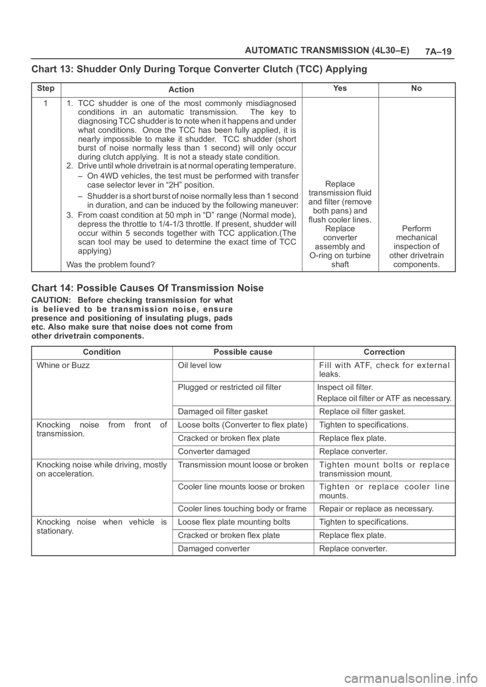
7A–19 AUTOMATIC TRANSMISSION (4L30–E)
Chart 13: Shudder Only During Torque Converter Clutch (TCC) Applying
StepActionYe sNo
11. TCC shudder is one of the most commonly misdiagnosed
conditions in an automatic transmission. The key to
diagnosing TCC shudder is to note when it happens and under
what conditions. Once the TCC has been fully applied, it is
nearly impossible to make it shudder. TCC shudder (short
burst of noise normally less than 1 second) will only occur
during clutch applying. It is not a steady state condition.
2. Drive until whole drivetrain is at normal operating temperature.
– On 4WD vehicles, the test must be performed with transfer
case selector lever in “2H” position.
– Shudder is a short burst of noise normally less than 1 second
in duration, and can be induced by the following maneuver:
3. From coast condition at 50 mph in “D” range (Normal mode),
depress the throttle to 1/4-1/3 throttle. If present, shudder will
occur within 5 seconds together with TCC application.(The
scan tool may be used to determine the exact time of TCC
applying)
Was the problem found?
Replace
transmission fluid
and filter (remove
both pans) and
flush cooler lines.
Replace
converter
assembly and
O-ring on turbine
shaft
Perform
mechanical
inspection of
other drivetrain
components.
Chart 14: Possible Causes Of Transmission Noise
CAUTION: Before checking transmission for what
is believed to be transmission noise, ensure
presence and positioning of insulating plugs, pads
etc. Also make sure that noise does not come from
other drivetrain components.
Condition
Possible causeCorrection
Whine or BuzzOil level lowFill with ATF, check for external
leaks.
Plugged or restricted oil filterInspect oil filter.
Replace oil filter or ATF as necessary.
Damaged oil filter gasketReplace oil filter gasket.
Knocking noise from front of
transmission
Loose bolts (Converter to flex plate)Tighten to specifications.
transmission.Cracked or broken flex plateReplace flex plate.
Converter damagedReplace converter.
Knocking noise while driving, mostly
on acceleration.Transmission mount loose or brokenTighten mount bolts or replace
transmission mount.
Cooler line mounts loose or brokenTighten or replace cooler line
mounts.
Cooler lines touching body or frameRepair or replace as necessary.
Knocking noise when vehicle is
stationary
Loose flex plate mounting boltsTighten to specifications.
stationary.Cracked or broken flex plateReplace flex plate.
Damaged converterReplace converter.
Page 2207 of 6000
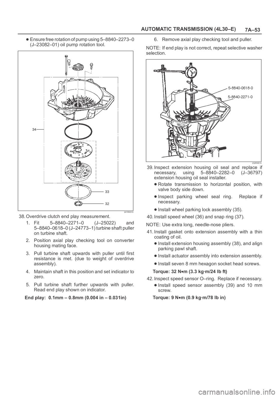
7A–53 AUTOMATIC TRANSMISSION (4L30–E)
Ensure free rotation of pump using 5–8840–2273–0
(J–23082–01) oil pump rotation tool.
241RW010
38. Overdrive clutch end play measurement.
1. Fit 5–8840–2271–0 (J–25022) and
5–8840–0618–0 (J–24773–1) turbine shaft puller
on turbine shaft.
2. Position axial play checking tool on converter
housing mating face.
3. Pull turbine shaft upwards with puller until first
resistance is met. (due to weight of overdrive
assembly).
4. Maintain shaft in this position and set indicator to
zero.
5. Pull turbine shaft further upwards with puller.
Read end play shown on indicator.
End play: 0.1mm – 0.8mm (0.004 in – 0.031in)6. Remove axial play checking tool and puller.
NOTE: If end play is not correct, repeat selective washer
selection.
252RW010
39. Inspect extension housing oil seal and replace if
necessary, using 5–8840–2282–0 (J–36797)
extension housing oil seal installer.
Rotate transmission to horizontal position, with
valve body side down.
Inspect parking wheel seal ring. Replace if
necessary.
Install wheel parking lock assembly (35).
40. Install speed wheel (36) and snap ring (37).
NOTE: Use extra long, needle-nose pliers.
41. Install gasket onto extension assembly with a thin
coating of oil.
Install extension housing assembly (38), and align
parking pawl shaft.
Install actuator assembly into extension assembly.
Install seven 8 mm hexagon socket head screws.
To r q u e : 3 2 N
m (3.3 kgꞏm/24 lb ft)
42. Inspect speed sensor O–ring. Replace if necessary.
Install speed sensor assembly (39) and 10 mm
screw.
To r q u e : 9 N
m (0.9 kgꞏm/78 lb in)
Page 2282 of 6000
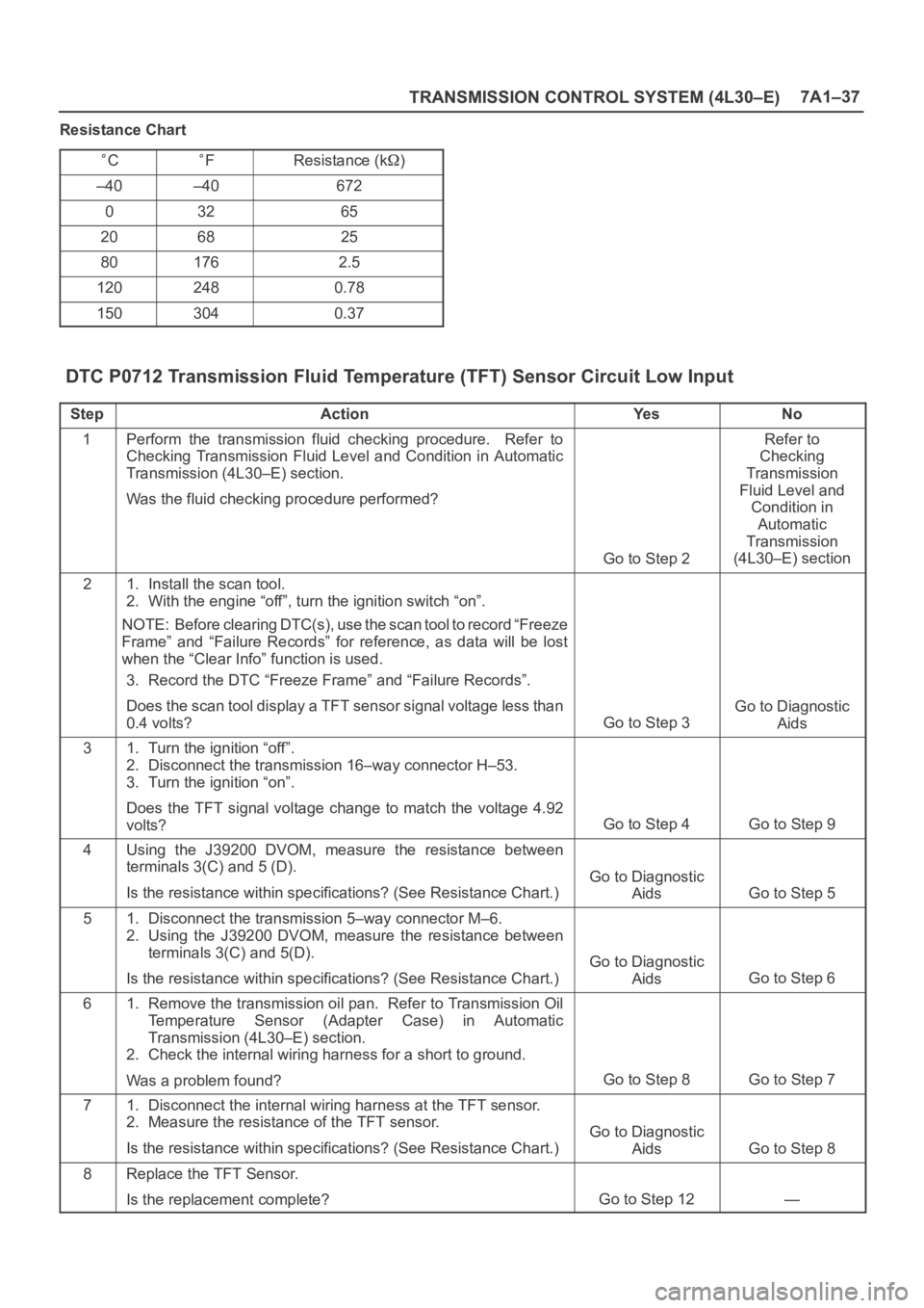
TRANSMISSION CONTROL SYSTEM (4L30–E)7A1–37
Resistance Chart
CFResistance (k)
–40–40672
03265
206825
801762.5
1202480.78
1503040.37
DTC P0712 Transmission Fluid Temperature (TFT) Sensor Circuit Low Input
StepActionYe sNo
1Perform the transmission fluid checking procedure. Refer to
Checking Transmission Fluid Level and Condition in Automatic
Transmission (4L30–E) section.
Was the fluid checking procedure performed?
Go to Step 2
Refer to
Checking
Transmission
Fluid Level and
Condition in
Automatic
Transmission
(4L30–E) section
21. Install the scan tool.
2. With the engine “off”, turn the ignition switch “on”.
NOTE: Before clearing DTC(s), use the scan tool to record “Freeze
Frame” and “Failure Records” for reference, as data will be lost
when the “Clear Info” function is used.
3. Record the DTC “Freeze Frame” and “Failure Records”.
Does the scan tool display a TFT sensor signal voltage less than
0.4 volts?
Go to Step 3
Go to Diagnostic
Aids
31. Turn the ignition “off”.
2. Disconnect the transmission 16–way connector H–53.
3. Turn the ignition “on”.
Does the TFT signal voltage change to match the voltage 4.92
volts?
Go to Step 4Go to Step 9
4Using the J39200 DVOM, measure the resistance between
terminals 3(C) and 5 (D).
Is the resistance within specifications? (See Resistance Chart.)
Go to Diagnostic
Aids
Go to Step 5
51. Disconnect the transmission 5–way connector M–6.
2. Using the J39200 DVOM, measure the resistance between
terminals 3(C) and 5(D).
Is the resistance within specifications? (See Resistance Chart.)
Go to Diagnostic
Aids
Go to Step 6
61. Remove the transmission oil pan. Refer to Transmission Oil
Temperature Sensor (Adapter Case) in Automatic
Transmission (4L30–E) section.
2. Check the internal wiring harness for a short to ground.
Was a problem found?
Go to Step 8Go to Step 7
71. Disconnect the internal wiring harness at the TFT sensor.
2. Measure the resistance of the TFT sensor.
Is the resistance within specifications? (See Resistance Chart.)
Go to Diagnostic
Aids
Go to Step 8
8Replace the TFT Sensor.
Is the replacement complete?
Go to Step 12—
Page 2285 of 6000
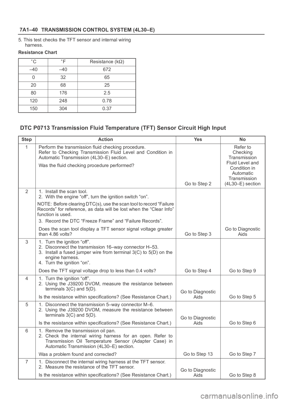
7A1–40
TRANSMISSION CONTROL SYSTEM (4L30–E)
5. This test checks the TFT sensor and internal wiring
harness.
Resistance Chart
CFResistance (k)
–40–40672
03265
206825
801762.5
1202480.78
1503040.37
DTC P0713 Transmission Fluid Temperature (TFT) Sensor Circuit High Input
StepActionYe sNo
1Perform the transmission fluid checking procedure.
Refer to Checking Transmission Fluid Level and Condition in
Automatic Transmission (4L30–E) section.
Was the fluid checking procedure performed?
Go to Step 2
Refer to
Checking
Transmission
Fluid Level and
Condition in
Automatic
Transmission
(4L30–E) section
21. Install the scan tool.
2. With the engine “off”, turn the ignition switch “on”.
NOTE: Before clearing DTC(s), use the scan tool to record “Failure
Records” for reference, as data will be lost when the “Clear Info”
function is used.
3. Record the DTC “Freeze Frame” and “Failure Records”.
Does the scan tool display a TFT sensor signal voltage greater
than 4.86 volts?
Go to Step 3
Go to Diagnostic
Aids
31. Turn the ignition “off”.
2. Disconnect the transmission 16–way connector H–53.
3. Install a fused jumper wire from terminal 3(C) to 5(D) on the
engine harness.
4. Turn the ignition “on”.
Does the TFT signal voltage drop to less than 0.4 volts?
Go to Step 4Go to Step 9
41. Turn the ignition “off”.
2. Using the J39200 DVOM, measure the resistance between
terminals 3(C) and 5(D).
Is the resistance within specifications? (See Resistance Chart.)
Go to Diagnostic
Aids
Go to Step 5
51. Disconnect the transmission 5–way connector M–6.
2. Using the J39200 DVOM, measure the resistance between
terminals 3(C) and 5(D).
Is the resistance within specifications? (See Resistance Chart.)
Go to Diagnostic
Aids
Go to Step 6
61. Remove the transmission oil pan.
2. Check the internal wiring harness for an open. Refer to
Transmission Oil Temperature Sensor (Adapter Case) in
Automatic Transmission (4L30–E) section.
Was a problem found and corrected?
Go to Step 13Go to Step 7
71. Disconnect the internal wiring harness at the TFT sensor.
2. Measure the resistance of the TFT sensor.
Is the resistance within specifications? (See Resistance Chart.)
Go to Diagnostic
Aids
Go to Step 8
Page 3501 of 6000
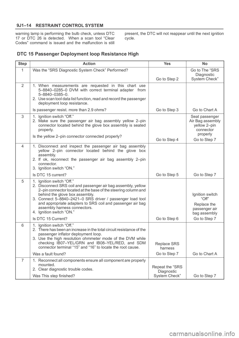
RESTRAINT CONTROL SYSTEM 9J1–14
warning lamp is performing the bulb check, unless DTC
17 or DTC 26 is detected. When a scan tool “Clear
Codes” command is issued and the malfunction is stillpresent, the DTC will not reappear until the next ignition
cycle.
DTC 15 Passenger Deployment loop Resistance High
StepActionYe sNo
1Was the “SRS Diagnostic System Check” Performed?
Go to Step 2
Go to The “SRS
Diagnostic
System Check”
21. When measurements are requested in this chart use
5–8840–0285–0 DVM with correct terminal adapter from
5–8840–0385–0.
2. Use scan tool data list function, read and record the passenger
deployment loop resistance.
Is passenger resist. more than 2.9 ohms?
Go to Step 3Go to Chart A
31. Ignition switch “Off.”
2. Make sure the passenger air bag assembly yellow 2–pin
connector located behind the glove box assembly is seated
properly.
Is the yellow 2–pin connector connected properly?
Go to Step 4
Seat passenger
Air Bag assembly
yellow 2–pin
connector
properly
Go to Step 7
41. Disconnect and inspect the passenger air bag assembly
yellow 2–pin connector located behind the glove box
assembly.
2. If ok, reconnect the passenger air bag assembly 2–pin
connector.
3. Ignition switch “ON.”
Is DTC 15 current?
Go to Step 5Go to Step 7
51. Ignition switch “Off.”
2. Disconnect SRS coil and passenger air bag assembly, yellow
2–pin connector located at the base of the steering column and
behind the glove box assembly.
3. Connect 5–8840–2421–0 SRS driver / passenger load tool
and appropriate adapters to SRS coil and passenger air bag
assembly harness connectors.
4. Ignition switch “ON.”
Is DTC 15 Current?
Go to Step 6
Ignition switch
“Off”
Replace the
passenger air
bag assembly
Go to Step 7
61. Ignition switch “Off.”
2. There has been an increase in the total circuit resistance of t h e
passenger inflator deployment loop.
3. Use the high resolution ohmmeter mode of the DVM while
checking IB07–YEL/GRN and IB08–YEL/RED, and SDM
connector terminal “15” and “16” to locate the root cause.
Was a fault found?
Replace SRS
harness
Go to Step 7
Go to Chart A
71. Reconnect all components ensure all component are properly
mounted.
2. Clear diagnostic trouble codes.
Was This step finished?
Repeat the “SRS
Diagnostic
System Check”
Go to Step 7
Page 3503 of 6000
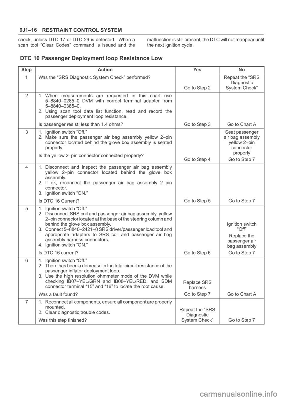
RESTRAINT CONTROL SYSTEM 9J1–16
check, unless DTC 17 or DTC 26 is detected. When a
scan tool “Clear Codes” command is issued and themalfunction is still present, the DTC will not reappear until
the next ignition cycle.
DTC 16 Passenger Deployment loop Resistance Low
StepActionYe sNo
1Was the “SRS Diagnostic System Check” performed?
Go to Step 2
Repeat the “SRS
Diagnostic
System Check”
21. When measurements are requested in this chart use
5–8840–0285–0 DVM with correct terminal adapter from
5–8840–0385–0.
2. Using scan tool data list function, read and record the
passenger deployment loop resistance.
Is passenger resist. less than 1.4 ohms?
Go to Step 3Go to Chart A
31. Ignition switch “Off.”
2. Make sure the passenger air bag assembly yellow 2–pin
connector located behind the glove box assembly is seated
properly.
Is the yellow 2–pin connector connected properly?
Go to Step 4
Seat passenger
air bag assembly
yellow 2–pin
connector
properly
Go to Step 7
41. Disconnect and inspect the passenger air bag assembly
yellow 2–pin connector located behind the glove box
assembly.
2. If ok, reconnect the passenger air bag assembly 2–pin
connector.
3. Ignition switch “ON.”
Is DTC 16 Current?
Go to Step 5Go to Step 7
51. Ignition switch “Off.”
2. Disconnect SRS coil and passenger air bag assembly, yellow
2–pin connector located at the base of the steering column and
behind the glove box assembly.
3. Connect 5–8840–2421–0 SRS driver/passenger load tool and
appropriate adapters to SRS coil and passenger air bag
assembly harness connectors.
4. Ignition switch “ON.”
Is DTC 16 current?
Go to Step 6
Ignition switch
“Off”
Replace the
passenger air
bag assembly
Go to Step 7
61. Ignition switch “Off.”
2. There has been a decrease in the total circuit resistance of the
passenger inflator deployment loop.
3. Use the high resolution ohmmeter mode of the DVM while
checking IB07–YEL/GRN and IB08–YEL/RED, and SDM
connector terminal “15” and “16” to locate the root cause.
Was a fault found?
Replace SRS
harness
Go to Step 7
Go to Chart A
71. Reconnect all components, ensure all component are properly
mounted.
2. Clear diagnostic trouble codes.
Was this step finished?
Repeat the “SRS
Diagnostic
System Check”
Go to Step 7
Page 3505 of 6000
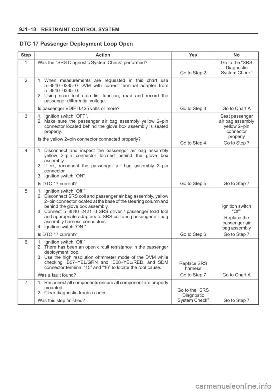
RESTRAINT CONTROL SYSTEM 9J1–18
DTC 17 Passenger Deployment Loop Open
StepActionYe sNo
1Was the “SRS Diagnostic System Check” performed?
Go to Step 2
Go to the “SRS
Diagnostic
System Check”
21. When measurements are requested in this chart use
5–8840–0285–0 DVM with correct terminal adapter from
5–8840–0385–0.
2. Using scan tool data list function, read and record the
passenger differential voltage.
Is passenger VDIF 0.425 volts or more?
Go to Step 3Go to Chart A
31. Ignition switch “OFF”.
2. Make sure the passenger air bag assembly yellow 2–pin
connector located behind the glove box assembly is seated
properly.
Is the yellow 2–pin connector connected properly?
Go to Step 4
Seat passenger
air bag assembly
yellow 2–pin
connector
properly
Go to Step 7
41. Disconnect and inspect the passenger air bag assembly
yellow 2–pin connector located behind the glove box
assembly.
2. If ok, reconnect the passenger air bag assembly 2–pin
connector.
3. Ignition switch “ON”.
Is DTC 17 current?
Go to Step 5Go to Step 7
51. Ignition switch “Off.”
2. Disconnect SRS coil and passenger air bag assembly, yellow
2–pin connector located at the base of the steering column and
behind the glove box assembly.
3. Connect 5–8840–2421–0 SRS driver / passenger load tool
and appropriate adapters to SRS coil and passenger air bag
assembly harness connectors.
4. Ignition switch “ON.”
Is DTC 17 current?
Go to Step 6
Ignition switch
“Off”
Replace the
passenger air
bag assembly
Go to Step 7
61. Ignition switch “Off.”
2. There has been an open circuit resistance in the passenger
deployment loop.
3. Use the high resolution ohmmeter mode of the DVM while
checking IB07–YEL/GRN and IB08–YEL/RED, and SDM
connector terminal “15” and “16” to locate the root cause.
Was a fault found?
Replace SRS
harness
Go to Step 7
Go to Chart A
71. Reconnect all components ensure all component are properly
mounted.
2. Clear diagnostic trouble codes.
Was this step finished?
Go to the “SRS
Diagnostic
System Check”
Go to Step 7
Page 3511 of 6000
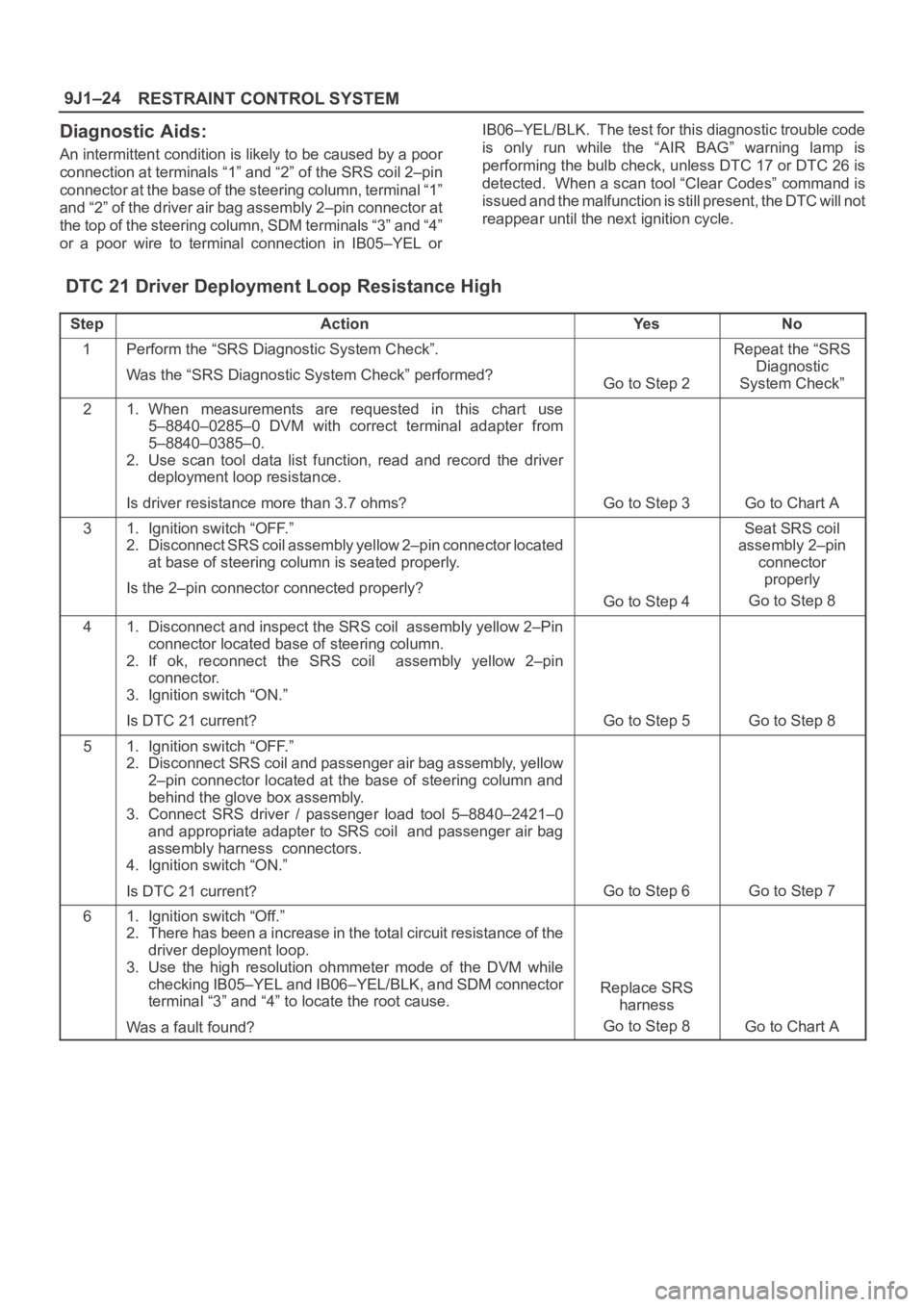
RESTRAINT CONTROL SYSTEM 9J1–24
Diagnostic Aids:
An intermittent condition is likely to be caused by a poor
connection at terminals “1” and “2” of the SRS coil 2–pin
connector at the base of the steering column, terminal “1”
and “2” of the driver air bag assembly 2–pin connector at
the top of the steering column, SDM terminals “3” and “4”
or a poor wire to terminal connection in IB05–YEL orIB06–YEL/BLK. The test for this diagnostic trouble code
is only run while the “AIR BAG” warning lamp is
performing the bulb check, unless DTC 17 or DTC 26 is
detected. When a scan tool “Clear Codes” command is
issued and the malfunction is still present, the DTC will not
reappear until the next ignition cycle.
DTC 21 Driver Deployment Loop Resistance High
StepActionYe sNo
1Perform the “SRS Diagnostic System Check”.
Was the “SRS Diagnostic System Check” performed?
Go to Step 2
Repeat the “SRS
Diagnostic
System Check”
21. When measurements are requested in this chart use
5–8840–0285–0 DVM with correct terminal adapter from
5–8840–0385–0.
2. Use scan tool data list function, read and record the driver
deployment loop resistance.
Is driver resistance more than 3.7 ohms?
Go to Step 3Go to Chart A
31. Ignition switch “OFF.”
2. Disconnect SRS coil assembly yellow 2–pin connector located
at base of steering column is seated properly.
Is the 2–pin connector connected properly?
Go to Step 4
Seat SRS coil
assembly 2–pin
connector
properly
Go to Step 8
41. Disconnect and inspect the SRS coil assembly yellow 2–Pin
connector located base of steering column.
2. If ok, reconnect the SRS coil assembly yellow 2–pin
connector.
3. Ignition switch “ON.”
Is DTC 21 current?
Go to Step 5Go to Step 8
51. Ignition switch “OFF.”
2. Disconnect SRS coil and passenger air bag assembly, yellow
2–pin connector located at the base of steering column and
behind the glove box assembly.
3. Connect SRS driver / passenger load tool 5–8840–2421–0
and appropriate adapter to SRS coil and passenger air bag
assembly harness connectors.
4. Ignition switch “ON.”
Is DTC 21 current?
Go to Step 6Go to Step 7
61. Ignition switch “Off.”
2. There has been a increase in the total circuit resistance of the
driver deployment loop.
3. Use the high resolution ohmmeter mode of the DVM while
checking IB05–YEL and IB06–YEL/BLK, and SDM connector
terminal “3” and “4” to locate the root cause.
Was a fault found?
Replace SRS
harness
Go to Step 8
Go to Chart A