1998 OPEL FRONTERA checking oil
[x] Cancel search: checking oilPage 5419 of 6000
6D – 16 ENGINE ELECTRICAL
DIAGNOSIS
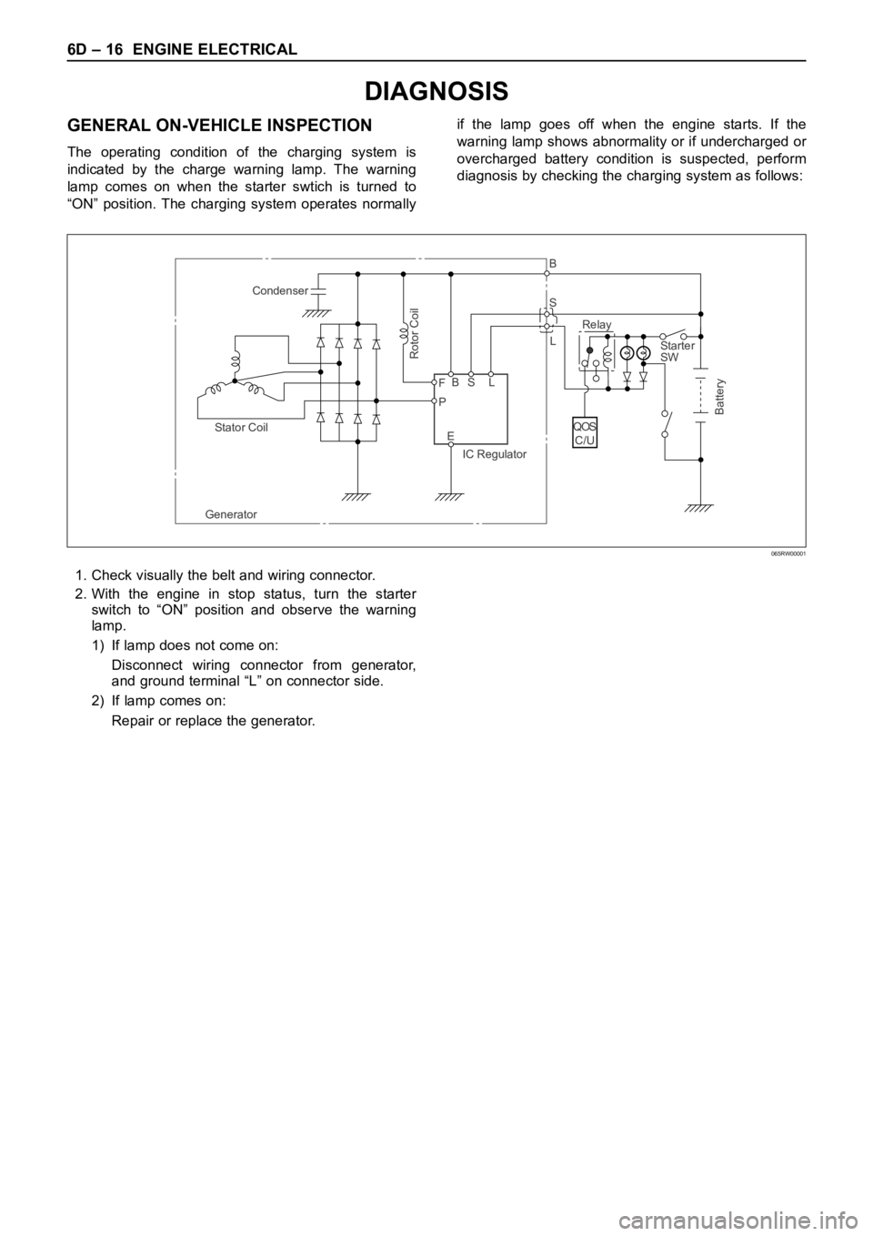
GENERAL ON-VEHICLE INSPECTION
The operating condition of the charging system is
indicated by the charge warning lamp. The warning
lamp comes on when the starter swtich is turned to
“ON” position. The charging system operates normallyif the lamp goes off when the engine starts. If the
warning lamp shows abnormality or if undercharged or
overcharged battery condition is suspected, perform
diagnosis by checking the charging system as follows:
Condenser
GeneratorStator Coil
IC RegulatorStarter
SW
Rotor Coil
Battery
P F
EBS LRelay B
S
L
QOS
C/U
065RW00001
1. Check visually the belt and wiring connector.
2. With the engine in stop status, turn the starter
switch to “ON” position and observe the warning
lamp.
1) If lamp does not come on:
Disconnect wiring connector from generator,
and ground terminal “L” on connector side.
2) If lamp comes on:
Repair or replace the generator.
Page 5454 of 6000
6E–25 4JX1–TC ENGINE DRIVEABILITY AND EMISSIONS
General Service Information
Serviceability Issues
Non-OEM Parts
All of the OBD diagnostics have been calibrated to run
with OEM parts. Accordingly, if commercially sold sensor
or switch is installed, it makes a wrong diagnosis and turn
on the MIL (“Check Engine” lamp).
Aftermarket electronics, such as cellular phones,
stereos, and anti-theft devices, may radiate EMI into the
control system if they are improperly installed. This may
cause a false sensor reading and turn on the MIL (“Check
Engine” lamp).
Poor Vehicle Maintenance
The sensitivity of OBD diagnostics will cause the MIL
(“Check Engine” lamp) to turn on if the vehicle is not
maintained properly. Restricted oil filters, fuel filters, and
crankcase deposits due to lack of oil changes or improper
oil viscosity can trigger actual vehicle faults that were not
previously monitored prior to OBD. Poor vehicle
maintenance can not be classified as a “non-vehicle
fault”, but with the sensitivity of OBD diagnostics, vehicle
maintenance schedules must be more closely followed.
Related System Faults
Many of the OBD system diagnostics will not run if the
ECM detects a fault on a related system or component.
Visual/Physical Engine Compartment
Inspection
Perform a careful visual and physical engine
compartment inspection when performing any diagnostic
procedure or diagnosing the cause of an emission test
failure. This can often lead to repairing a problem without
further steps. Use the following guidelines when
performing a visual/physical inspection:
Inspect all vacuum hoses for punches, cuts,
disconnects, and correct routing.
Inspect hoses that are difficult to see behind other
components.
Inspect all wires in the engine compartment for proper
connections, burned or chafed spots, pinched wires,
contact with sharp edges or contact with hot exhaust
manifolds or pipes.
Basic Knowledge of Tools Required
NOTE: Lack of basic knowledge of this powertrain when
performing diagnostic procedures could result in an
incorrect diagnosis or damage to powertrain
components. Do not attempt to diagnose a powertrain
problem without this basic knowledge.
A basic understanding of hand tools is necessary to effec-
tively use this section of the Service Manual.
Serial Data Communications
Class II Serial Data Communications
This vehicle utilizes the “Class II” communication system.
Each bit of information can have one of two lengths: longor short. This allows vehicle wiring to be reduced by
transmitting and receiving multiple signals over a single
wire. The messages carried on Class II data streams are
also prioritized. If two messages attempt to establish
communications on the data line at the same time, only
the message with higher priority will continue. The device
with the lower priority message must wait.
On this vehicle the Tech 2 displays the actual values for
vehicle parameters. It will not be necessary to perform
any conversions from coded values to actual values.
On-Board Diagnostic (OBD)
On-Board Diagnostic Tests
A diagnostic test is a series of steps, the result of which is
a pass or fail reported to the diagnostic executive. When
a diagnostic test reports a pass result, the diagnostic
executive records the following data:
The diagnostic test has been completed since the last
ignition cycle.
The diagnostic test has passed during the current
ignition cycle.
The fault identified by the diagnostic test is not
currently active.
When a diagnostic test reports a fail result, the diagnostic
executive records the following data:
The diagnostic test has been completed since the last
ignition cycle.
The fault identified by the diagnostic test is currently
active.
The fault has been active during this ignition cycle.
The operating conditions at the time of the failure.
Comprehensive Component Monitor
Diagnostic Operation
Comprehensive component monitoring diagnostics are
required to operate engine properly.
Input Components:
Input components are monitored for circuit continuity and
out-of-range values. This includes rationality checking.
Rationality checking refers to indicating a fault when the
signal from a sensor does not seem reasonable. Accel
Position (AP) sensor that indicates high throttle position
at low engine loads or MAP voltage. Input components
may include, but are not limited to the following sensors:
Intake Air Temperature (IAT) Sensor
Crankshaft Position (CKP) Sensor
Intake throttle Position (ITP) Sensor
Engine Coolant Temperature (ECT) Sensor
Camshaft Position (CMP) Sensor
Manifold absolute Pressure (MAP) Sensor
Accel Position Sensor
Fuel Temp Sensor
Rail Pressure Sensor
Oil Temp Sensor
EGR Pressure Sensor
Vehicle Speed Sensor
Page 5690 of 6000
7A–1 AUTOMATIC TRANSMISSION (4L30–E)
TRANSMISSION
AUTOMATIC TRANSMISSION (4L30–E)
CONTENTS
Service Precaution 7A–3. . . . . . . . . . . . . . . . . . . . . .
Construction 7A–3. . . . . . . . . . . . . . . . . . . . . . . . . . . .
Range Reference Chart 7A–4. . . . . . . . . . . . . . . . . .
Normal Operation Of 2000 4L30–E
Transmission 7A–5. . . . . . . . . . . . . . . . . . . . . . . . . . .
Diagnosis 7A–5. . . . . . . . . . . . . . . . . . . . . . . . . . . . . .
Driver Information 7A–5. . . . . . . . . . . . . . . . . . . . . . .
General Diagnosis Procedure 7A–8. . . . . . . . . . . . .
Preliminary Inspection Chart 7A–9. . . . . . . . . . . . . .
Checking Transmission Fluid Level and
Condition 7A–10. . . . . . . . . . . . . . . . . . . . . . . . . . . . . .
Test Driving 7A–11. . . . . . . . . . . . . . . . . . . . . . . . . . . . .
Mechanical / Hydraulic Diagnosis Check Trans
Indicator Chart 7A–12. . . . . . . . . . . . . . . . . . . . . . . . . .
Mechanical / Hydraulic Diagnosis
Symptoms Index 7A–13. . . . . . . . . . . . . . . . . . . . . . . .
Stall Test 7A–23. . . . . . . . . . . . . . . . . . . . . . . . . . . . . . .
Line Pressure Test 7A–23. . . . . . . . . . . . . . . . . . . . . .
Shift Speed Chart (V6 3.2L 6VD1 Model) 7A–24. . .
Shift Speed Chart (V6 3.5L 6VE1 Model) 7A–26. .
Lockup Speed Chart (V6 3.2L 6VD1 Model) 7A–28
Lockup Speed Chart (V6 3.5L 6VE1 Model) 7A–28
Changing Transmission Fluid 7A–29. . . . . . . . . . . . .
Selector Lever 7A–29. . . . . . . . . . . . . . . . . . . . . . . . . .
Inspection 7A–29. . . . . . . . . . . . . . . . . . . . . . . . . . . .
Removal 7A–30. . . . . . . . . . . . . . . . . . . . . . . . . . . . .
Installation 7A–30. . . . . . . . . . . . . . . . . . . . . . . . . . . .
Mode Switch 7A–31. . . . . . . . . . . . . . . . . . . . . . . . . . . .
Removal 7A–31. . . . . . . . . . . . . . . . . . . . . . . . . . . . .
Installation 7A–31. . . . . . . . . . . . . . . . . . . . . . . . . . . .
Transmission (With Transfer Case) 7A–33. . . . . . . .
Transmission And Associated Parts 7A–33. . . . . .
Removal 7A–33. . . . . . . . . . . . . . . . . . . . . . . . . . . . .
Installation 7A–35. . . . . . . . . . . . . . . . . . . . . . . . . . . .
Solenoid (Main Case Valve Body) 7A–39. . . . . . . . .
Removal 7A–39. . . . . . . . . . . . . . . . . . . . . . . . . . . . .
Installation 7A–39. . . . . . . . . . . . . . . . . . . . . . . . . . . .
Solenoid (Adapter Case Valve Body) 7A–40. . . . . . .
Removal 7A–40. . . . . . . . . . . . . . . . . . . . . . . . . . . . .
Installation 7A–40. . . . . . . . . . . . . . . . . . . . . . . . . . . .
Valve Body Assembly (Main Case) 7A–41. . . . . . . .
Removal 7A–41. . . . . . . . . . . . . . . . . . . . . . . . . . . . .
Installation 7A–41. . . . . . . . . . . . . . . . . . . . . . . . . . . .
Valve Body Assembly (Adapter Case) 7A–43. . . . . .
Removal 7A–43. . . . . . . . . . . . . . . . . . . . . . . . . . . . . Installation 7A–43. . . . . . . . . . . . . . . . . . . . . . . . . . . .
Powertrain Control Module (PCM) 7A–43. . . . . . . . .
Removal 7A–43. . . . . . . . . . . . . . . . . . . . . . . . . . . . .
Installation 7A–43. . . . . . . . . . . . . . . . . . . . . . . . . . . .
Speed Sensor (Extension Housing) 7A–44. . . . . . . .
Removal 7A–44. . . . . . . . . . . . . . . . . . . . . . . . . . . . .
Installation 7A–44. . . . . . . . . . . . . . . . . . . . . . . . . . . .
Transmission Oil Temperature Sensor
(Adapter Case) 7A–44. . . . . . . . . . . . . . . . . . . . . . . . .
Removal 7A–44. . . . . . . . . . . . . . . . . . . . . . . . . . . . .
Installation 7A–45. . . . . . . . . . . . . . . . . . . . . . . . . . . .
Front Oil Seal (Converter Housing) 7A–45. . . . . . . .
Removal 7A–45. . . . . . . . . . . . . . . . . . . . . . . . . . . . .
Installation 7A–45. . . . . . . . . . . . . . . . . . . . . . . . . . . .
Rear Oil Seal (Extension Housing) 7A–46. . . . . . . . .
Removal 7A–46. . . . . . . . . . . . . . . . . . . . . . . . . . . . .
Installation 7A–46. . . . . . . . . . . . . . . . . . . . . . . . . . . .
Transmission (4L30–E) 7A–46. . . . . . . . . . . . . . . . . .
Disassembly 7A–46. . . . . . . . . . . . . . . . . . . . . . . . . .
Reassembly 7A–50. . . . . . . . . . . . . . . . . . . . . . . . . .
Converter Housing And Oil Pump Assembly 7A–60
Disassembled View 7A–60. . . . . . . . . . . . . . . . . . . .
Disassembly 7A–60. . . . . . . . . . . . . . . . . . . . . . . . . .
Inspection And Repair 7A–60. . . . . . . . . . . . . . . . . .
Reassembly 7A–60. . . . . . . . . . . . . . . . . . . . . . . . . .
Oil Pump 7A–61. . . . . . . . . . . . . . . . . . . . . . . . . . . . . . .
Disassembled View 7A–61. . . . . . . . . . . . . . . . . . . .
Disassembly 7A–61. . . . . . . . . . . . . . . . . . . . . . . . . .
Inspection And Repair 7A–61. . . . . . . . . . . . . . . . . .
Reassembly 7A–61. . . . . . . . . . . . . . . . . . . . . . . . . .
Main Case Valve Body 7A–62. . . . . . . . . . . . . . . . . . .
Disassembled View 7A–62. . . . . . . . . . . . . . . . . . . .
Disassembly 7A–62. . . . . . . . . . . . . . . . . . . . . . . . . .
Inspection And Repair 7A–63. . . . . . . . . . . . . . . . . .
Reassembly 7A–63. . . . . . . . . . . . . . . . . . . . . . . . . .
Adapter Case Valve Body 7A–64. . . . . . . . . . . . . . . .
Disassembled View 7A–64. . . . . . . . . . . . . . . . . . . .
Disassembly 7A–64. . . . . . . . . . . . . . . . . . . . . . . . . .
Inspection And Repair 7A–64. . . . . . . . . . . . . . . . . .
Reassembly 7A–64. . . . . . . . . . . . . . . . . . . . . . . . . .
Third Clutch And Sprag Unit 7A–65. . . . . . . . . . . . . .
Disassembled View 7A–65. . . . . . . . . . . . . . . . . . . .
Disassembly 7A–65. . . . . . . . . . . . . . . . . . . . . . . . . .
Inspection And Repair 7A–66. . . . . . . . . . . . . . . . . .
Page 5699 of 6000
7A–10
AUTOMATIC TRANSMISSION (4L30–E)
Checking Transmission Fluid Level
and Condition
Checking fluid level and condition (color and odor) at
regular intervals will provide early diagnosis information
about the transmission. This information may be used to
correct a condition that, if not detected early, could result
in major transmission repairs.
IMPORTANT:When new, automatic transmission fluid
is red in color. As the vehicle is driven, the transmission
fluid will begin to look darker in color. The color may
eventually appear light brown.
A dark brown color with burnt odor may indicate
excessive fluid deterioration and signal a need for fluid
change.
Fluid Level
When adding or changing fluid, use only DEXRON –III.
Refer to Maintenance and Lubrication in General
Information section for maintenance information and
servicing interval.
CAUTION: DO NOT OVERFILL.
Overfilling will cause foaming, loss of fluid, abnor-
mal shifting and possible damage to the transmis-
sion.
1. Park the vehicle on level ground and apply the parking
brake firmly.
2. Check fluid level with engine running at idle.
NOTE: Be sure that transmission fluid temperature is
below 30
C (86F).
3. Move the selector lever through all gear ranges.
4. Move the selector lever to “Park”.
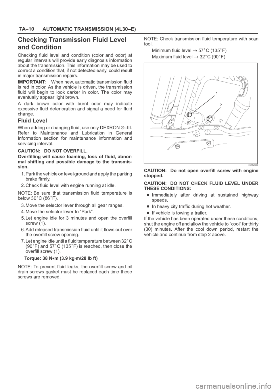
5. Let engine idle for 3 minutes and open the overfill
screw (1).
6. Add released transmission fluid until it flows out over
the overfill screw opening.
7. Let engine idle until a fluid temperature between 32
C
(90
F) and 57C (135F) is reached, then close the
overfill screw (1).
Torque: 38 N
m (3.9 kgꞏm/28 lb ft)
NOTE: To prevent fluid leaks, the overfill screw and oil
drain screws gasket must be replaced each time these
screws are removed.NOTE: Check transmission fluid temperature with scan
tool.
Minimum fluid level
57C (135F)
Maximum fluid level
32C (90F)
242RW003
CAUTION: Do not open overfill screw with engine
stopped.
CAUTION: DO NOT CHECK FLUID LEVEL UNDER
THESE CONDITIONS:
Immediately after driving at sustained highway
speeds.
In heavy city traffic during hot weather.
If vehicle is towing a trailer.
If the vehicle has been operated under these conditions,
shut the engine off and allow the vehicle to “cool” for thirty
(30) minutes. After the cool down period, restart the
vehicle and continue from step 2 above.
Page 5708 of 6000
7A–19 AUTOMATIC TRANSMISSION (4L30–E)
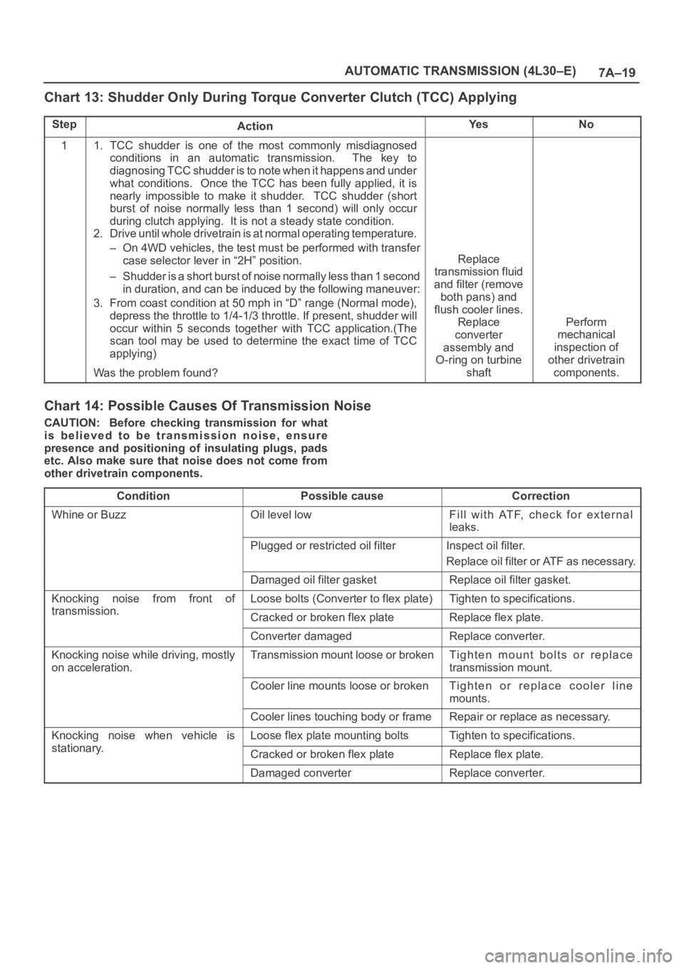
Chart 13: Shudder Only During Torque Converter Clutch (TCC) Applying
StepActionYe sNo
11. TCC shudder is one of the most commonly misdiagnosed
conditions in an automatic transmission. The key to
diagnosing TCC shudder is to note when it happens and under
what conditions. Once the TCC has been fully applied, it is
nearly impossible to make it shudder. TCC shudder (short
burst of noise normally less than 1 second) will only occur
during clutch applying. It is not a steady state condition.
2. Drive until whole drivetrain is at normal operating temperature.
– On 4WD vehicles, the test must be performed with transfer
case selector lever in “2H” position.
– Shudder is a short burst of noise normally less than 1 second
in duration, and can be induced by the following maneuver:
3. From coast condition at 50 mph in “D” range (Normal mode),
depress the throttle to 1/4-1/3 throttle. If present, shudder will
occur within 5 seconds together with TCC application.(The
scan tool may be used to determine the exact time of TCC
applying)
Was the problem found?
Replace
transmission fluid
and filter (remove
both pans) and
flush cooler lines.
Replace
converter
assembly and
O-ring on turbine
shaft
Perform
mechanical
inspection of
other drivetrain
components.
Chart 14: Possible Causes Of Transmission Noise
CAUTION: Before checking transmission for what
is believed to be transmission noise, ensure
presence and positioning of insulating plugs, pads
etc. Also make sure that noise does not come from
other drivetrain components.
Condition
Possible causeCorrection
Whine or BuzzOil level lowFill with ATF, check for external
leaks.
Plugged or restricted oil filterInspect oil filter.
Replace oil filter or ATF as necessary.
Damaged oil filter gasketReplace oil filter gasket.
Knocking noise from front of
transmission
Loose bolts (Converter to flex plate)Tighten to specifications.
transmission.Cracked or broken flex plateReplace flex plate.
Converter damagedReplace converter.
Knocking noise while driving, mostly
on acceleration.Transmission mount loose or brokenTighten mount bolts or replace
transmission mount.
Cooler line mounts loose or brokenTighten or replace cooler line
mounts.
Cooler lines touching body or frameRepair or replace as necessary.
Knocking noise when vehicle is
stationary
Loose flex plate mounting boltsTighten to specifications.
stationary.Cracked or broken flex plateReplace flex plate.
Damaged converterReplace converter.
Page 5745 of 6000
7A–56
AUTOMATIC TRANSMISSION (4L30–E)
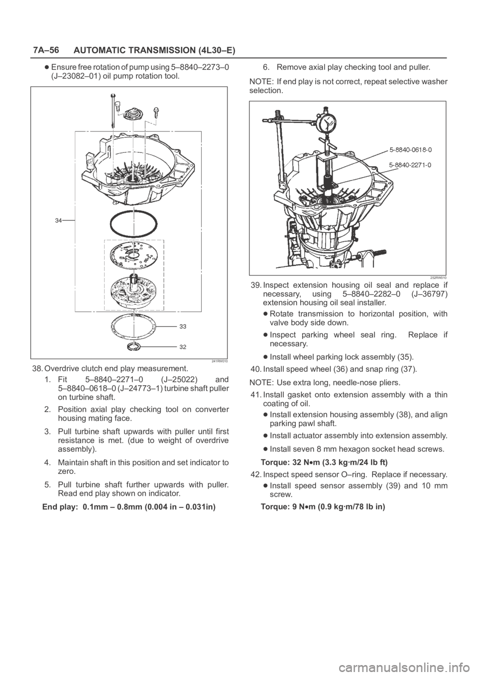
Ensure free rotation of pump using 5–8840–2273–0
(J–23082–01) oil pump rotation tool.
241RW010
38. Overdrive clutch end play measurement.
1. Fit 5–8840–2271–0 (J–25022) and
5–8840–0618–0 (J–24773–1) turbine shaft puller
on turbine shaft.
2. Position axial play checking tool on converter
housing mating face.
3. Pull turbine shaft upwards with puller until first
resistance is met. (due to weight of overdrive
assembly).
4. Maintain shaft in this position and set indicator to
zero.
5. Pull turbine shaft further upwards with puller.
Read end play shown on indicator.
End play: 0.1mm – 0.8mm (0.004 in – 0.031in)6. Remove axial play checking tool and puller.
NOTE: If end play is not correct, repeat selective washer
selection.
252RW010
39. Inspect extension housing oil seal and replace if
necessary, using 5–8840–2282–0 (J–36797)
extension housing oil seal installer.
Rotate transmission to horizontal position, with
valve body side down.
Inspect parking wheel seal ring. Replace if
necessary.
Install wheel parking lock assembly (35).
40. Install speed wheel (36) and snap ring (37).
NOTE: Use extra long, needle-nose pliers.
41. Install gasket onto extension assembly with a thin
coating of oil.
Install extension housing assembly (38), and align
parking pawl shaft.
Install actuator assembly into extension assembly.
Install seven 8 mm hexagon socket head screws.
To r q u e : 3 2 N
m (3.3 kgꞏm/24 lb ft)
42. Inspect speed sensor O–ring. Replace if necessary.
Install speed sensor assembly (39) and 10 mm
screw.
To r q u e : 9 N
m (0.9 kgꞏm/78 lb in)
Page 5826 of 6000

AUTOMATIC TRANSMISSION (AW30-40LE) 7A–45
• Changes solenoid output pattern as following figure
The shift theory at shift solenoid failure
At failure decision
Executes following items in addition to above control
items at failure detection.
•Turns Solenoid power supply OFF
•Blinks "CHECK TRANS" lamp
•Stores the failure information in failure-memory
*Prohibits failure detection of S1, S2, SL, STH,
Selector position switch, and Oil temp. sensor.
Conditions of turning "CHECK TRANS" off:
Turns "CHECK TRANS" lamp off after ignition is turned
ON
OFF ON.
Reversion conditions from fail-safe:
At failure detection
When a normal judgment is obtained by rechecking
during shifting.
At failure decision
Recovers at the same time as the conditions of
turning “CHECK TRANS” lamp off are satisfied.
Test description:
The following numbers correspond to circled numbers on
the diagnostic char t.
(1) With the key "ON", the voltage between the TCM
terminals (C78-4) and (C78-15 or 19) is 8 to 16V.
(2) When the driving wheels revolve with the 3rd speed
gear, the voltage is 1 V or less.
(3) The solenoid resistance is within the range of 11 to
15
.
Diagnostic aids:
In case of faulty connection, open or shor ted circuit to
the TCM terminal (C78-4), DTC P0753 is displayed. A
intermittent failure may be caused by a poor connection,
rubbed through wire insulation or a wire broke inside the
insulation.Shift
lever
Po s i t i o nNormal S1 failure S2 filure S1 and S2 failure
Gear S1 S2 Gear S1 S2 Gear S1 S2 Gear S1 S2
D1
3
1
O/D 2O/D3
O/DO/D
213
1
3 2O/D3
L1313
2O/D
Page 5829 of 6000
7A–48 AUTOMATIC TRANSMISSION (AW30-40LE)
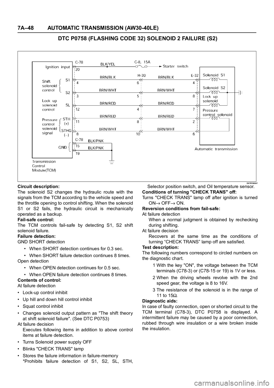
DTC P0758 (FLASHING CODE 32) SOLENOID 2 FAILURE (S2)
D07RY00047Circuit description:
The solenoid S2 changes the hydraulic route with the
signals from the TCM according to the vehicle speed and
the throttle opening to control shifting. When the solenoid
S1 or S2 fails, the hydraulic circuit is mechanically
operated as a backup.
Fail-safe control:
The TCM controls fail-safe by detecting S1, S2 shift
solenoid failure.
Failure detection:
GND SHORT detection
• When SHORT detection continues for 0.3 sec.
• When SHORT failure detection continues 8 times.
Open detection
• When OPEN detection continues for 0.5 sec.
• When OPEN failure detection continues 8 times.
Contents of control:
At failure detection
• Lock-up control inhibit
• Up hill and down hill control inhibit
• Squat control inhibit
• Changes solenoid output pattern as "The shift theory
at shift solenoid failure". (See DTC P0753)
At failure decision
Executes following items in addition to above control
items at failure detection.
• Turns Solenoid power supply OFF
• Blinks "CHECK TRANS" lamp
• Stores the failure information in failure-memory
*Prohibits failure detection of S1, S2, SL, STH,Selector position switch, and Oil temperature sensor.
Conditions of turning "CHECK TRANS" off:
Turns "CHECK TRANS" lamp off after ignition is turned
ON
OFF ON.
Reversion conditions from fail-safe:
At failure detection
When a normal judgment is obtained by rechecking
during shifting.
At failure decision
Recovers at the same time as the conditions of
turning “CHECK TRANS” lamp off are satisfied.
Test description:
The following numbers correspond to circled numbers on
the diagnostic char t.
1 With the key "ON", the voltage between the TCM
terminals (C78-3) or (C78-15 or 19) is 1V or less.
2 When the driving wheels revolve with the 2nd
speed gear, the voltage is 8 to 16V.
3 The resistance of the solenoid is in the range of
11 to 15
.
Diagnostic aids:
In case of faulty connection, open or shor ted circuit to the
TCM terminal (C78-3), DTC P0758 is displayed. A
intermittent failure may be caused by a poor connection,
rubbed through wire insulation or a wire broken inside
the insulation.