1998 OPEL FRONTERA ESP
[x] Cancel search: ESPPage 679 of 6000

4C–13 DRIVE SHAFT SYSTEM
9. Install lock washer and lock screw in the following
manner.
Turn the side with larger diameter of the tapered
bore to the vehicle outer side, then attach the
washer.
If the bolt holes in the lock plate are not aligned with
the corresponding holes in the nut, reverse the lock
plate.
If the bolt holes are still out of alignment, turn in the
nut just enough to obtain alignment.
Screw is to be fastened tightly so its head may
come lower than the surface of the washer.
411RS012
10. Apply adhesive (LOCTITE 515 or equivalent) to both
joining flange faces then install hub flange.
11. Install snap ring and shim.
Adjust the clearance between the free wheeling hub
body and the snap ring.
Clearance: 0 mm–0.3 mm (0 in–0.012 in)
Shims Available: 0.2 mm, 0.3 mm, 0.5 mm,
1.0 mm (0.008 in, 0.012 in, 0.020 in, 0.039 in)
411RW002
12. Install hub cap.
13. Tighten the bolts to the specified torque.
Torque: 59 Nꞏm (6.0 kgꞏm/43 lb ft)
Page 685 of 6000

4C–19 DRIVE SHAFT SYSTEM
21. Install lock washer and lock screw in the following
manner.
Turn the side with larger diameter of the tapered
bore to the vehicle outer side, and attach the
washer.
If the bolt holes in the lock plate are not aligned with
the corresponding holes in the nut, reverse the lock
plate.
If the bolt holes are still out of alignment, trun in the
nut just enough to obtain alignment.
Screw is to be fastened tightly so its head may
come lower than the surface of the washer.
411RS012
22. Install body assembly.
Apply adhesive (LOCTITE 515 or equivalent) to
both joining faces.
Tighten the bolts to the specified torque.
Torque:59Nꞏm (6.0kgꞏm/43lbft)
23. Install snap ring and shim.
Adjust the clearance between the free wheeling hub
body and the snap ring.
Clearance:
0-0.3mm (0-0.012in)
Shims Available:
0.2mm, 0.3mm, 0.5mm, 1.0mm, (0.008in, 0.012in,
0.020in, 0.039in)
411RW002
24. Install cover assembly.
Align stopper nails (1) to grooves of body (2).
411RW019
25. Tighten the cover bolts to the specified torque.
Torque:12Nꞏm (1.2kgꞏm/104lbin)
Page 796 of 6000

4D2–29 TRANSFER CASE (TOD)
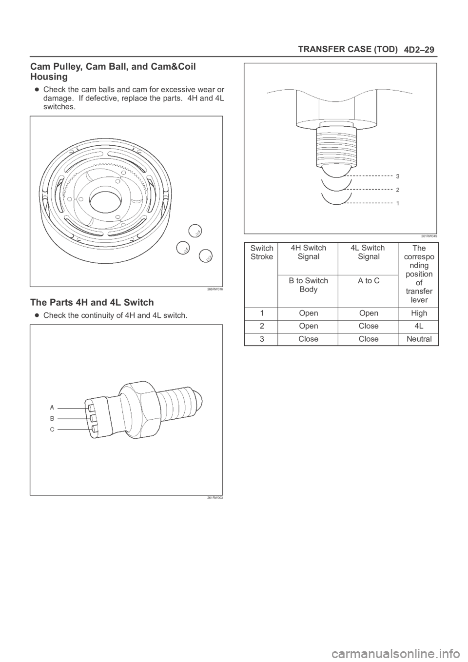
Cam Pulley, Cam Ball, and Cam&Coil
Housing
Check the cam balls and cam for excessive wear or
damage. If defective, replace the parts. 4H and 4L
switches.
266RW016
The Parts 4H and 4L Switch
Check the continuity of 4H and 4L switch.
261RW003
261RW049
Switch
Stroke4H Switch
Signal4L Switch
SignalThe
correspo
nding
p
ositionB to Switch
BodyA to Cosition
of
transfer
lever
1OpenOpenHigh
2OpenClose4L
3CloseCloseNeutral
Page 816 of 6000

5A–6
BRAKE CONTROL SYSTEM
Test Driving ABS Complaint Vehicles
In case that there has been an malfunction in the lighting
pattern of “ABS” warning light, the fault can be located in
accordance with the “DIAGNOSIS BY “ABS” WARNING
LIGHT ILLUMINATION PATTERN” . In case of such
trouble as can be detected by the driver as a vehicle
symptom, however, it is necessary to give a test drive
following the test procedure mentioned below, thereby
reproducing the symptom for trouble diagnosis on a
symptom basis:
1. Start the engine and make sure that the “ABS” W/L
goes OFF. If the W/L remains ON, it means that the
Diagnostic Trouble Code (DTC) is stored. Therefore,
read the code and locate the fault.
2. Start the vehicle and accelerate to about 30 km/h (19
mph) or more.
3. Slowly brake and stop the vehicle completely.
4. Then restart the vehicle and accelerate to about 40
km/h (25 mph) or more.
5. Brake at a time so as to actuate the ABS and stop the
vehicle.
6. Be cautious of abnormality during the test. If the W/L
is actuated while driving, read the DTC and locate the
fault.
7. If the abnormality is not reproduced by the test, make
best efforts to reproduce the situation reported by the
customer.
8. If the abnormality has been detected, repair in
accordance with the “SYMPTOM DIAGNOSIS” .NOTE:Be sure to give a test drive on a wide, even road with
little traffic.
If an abnormality is detected, be sure to suspend the
test and start trouble diagnosis at once.
“ABS” Warning Light
When ABS trouble occurs and actuates when possible
the “ABS” warning light, the trouble code corresponding
to the trouble is stored in the EHCU. Only the ordinary
brake system is available when the ABS is turned off.
When the “ABS” warning light is actuated, if the starter
switch is set ON after setting it OFF once, the EHCU
checks up on the entire system and, if there is no
abnormality, judges ABS to work currently and the
warning light works normally even though the trouble
code is stored.
NOTE: Illumination of the “ABS” warning light indicates
that anti-lock braking is no longer available. Power
assisted braking without anti-lock control is still available.
Normal Operation
“ABS” Warning Light
W h e n t h e i g n i t i o n i s f i r s t m o v e d f r o m “ O F F ” t o “ R U N ” , t h e
amber “ABS” warning light will turn “ON” . The “ABS”
warning light will turn “ON” during engine starting and will
usually stay “ON” for approximately three seconds after
the ignition switch is returned to the “ON” position. The
warning light should remain “OFF” at all other times.
Basic Diagnostic Flow Chart
StepActionYe sNo
11. Customer complaint.
2. Questioning to customer.
3. Basic inspection (Refer to “Basic inspection procedure”)
Using TECH 2?
Go to Step 2Go to Step 4
2Make sure of DTC by mode “F0: Diagnostic Trouble Codes”.
Is EHCU including DTC?
Go to Step 3Go to Step 5
31. Repair of faulty part.
2. Elimination of DTC.
3. Inspection of “ABS” W/L Illumination pattern with ignition SW
“ON”.
4. Test drive.
Does repeat trouble?
Repeat the
diagnosis it the
symptom or DTC
appears again Go
to Step 1
Go to Step 5
4Check if the DTC is stored.
Is EHCU including DTC?
Go to Step 3
Trouble diagnosis
based on
symptom (Refer
to “SYMPTOM
DIAGNOSIS”) Go
to Step 3
51. Reconnect all components and ensure all component are
properly mounted.
2. Clear diagnostic trouble code.
Was this step finished?
FinishedGo to Step 5
Page 968 of 6000

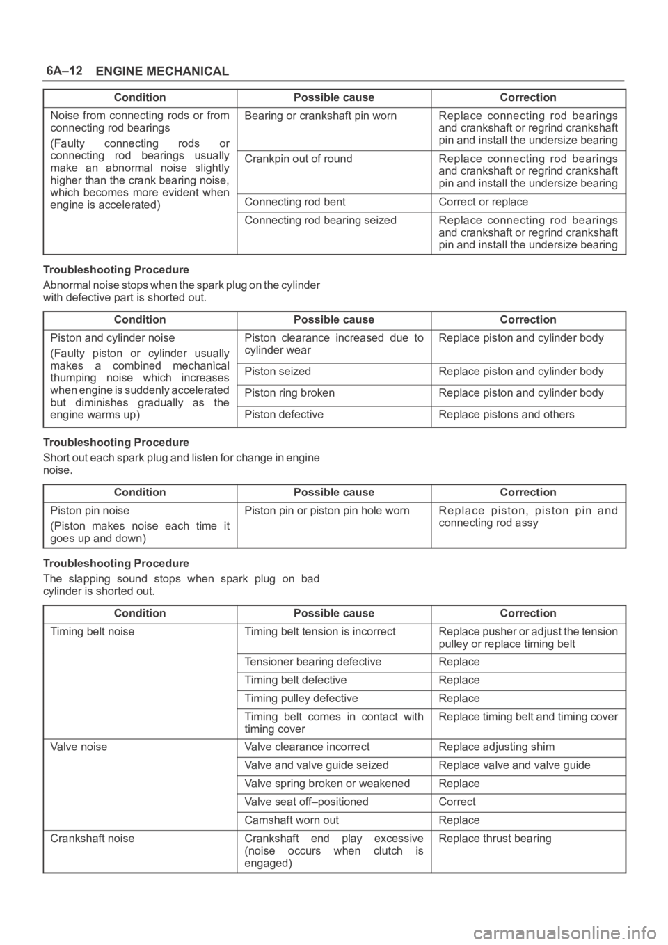
6A–12
ENGINE MECHANICAL
ConditionPossible causeCorrection
Noise from connecting rods or from
connecting rod bearings
(Faulty connecting rods orBearing or crankshaft pin wornReplace connecting rod bearings
and crankshaft or regrind crankshaft
pin and install the undersize bearing
yg
connecting rod bearings usually
make an abnormal noise slightly
higher than the crank bearing noise,
which becomes more evident when
Crankpin out of roundReplace connecting rod bearings
and crankshaft or regrind crankshaft
pin and install the undersize bearing
which becomes more evident when
engine is accelerated)Connecting rod bentCorrect or replaceg)
Connecting rod bearing seizedReplace connecting rod bearings
and crankshaft or regrind crankshaft
pin and install the undersize bearing
Troubleshooting Procedure
Abnormal noise stops when the spark plug on the cylinder
with defective part is shorted out.
Condition
Possible causeCorrection
Piston and cylinder noise
(Faulty piston or cylinder usually
kbidhil
Piston clearance increased due to
cylinder wearReplace piston and cylinder body
makes a combined mechanical
thumping noise which increasesPiston seizedReplace piston and cylinder bodyg
when engine is suddenly accelerated
but diminishes
gradually as thePiston ring brokenReplace piston and cylinder bodybut diminishes gradually as the
engine warms up)Piston defectiveReplace pistons and others
Troubleshooting Procedure
Short out each spark plug and listen for change in engine
noise.
Condition
Possible causeCorrection
Piston pin noise
(Piston makes noise each time it
goes up and down)Piston pin or piston pin hole wornReplace piston, piston pin and
connecting rod assy
Troubleshooting Procedure
The slapping sound stops when spark plug on bad
cylinder is shorted out.
Condition
Possible causeCorrection
Timing belt noiseTiming belt tension is incorrectReplace pusher or adjust the tension
pulley or replace timing belt
Tensioner bearing defectiveReplace
Timing belt defectiveReplace
Timing pulley defectiveReplace
Timing belt comes in contact with
timing coverReplace timing belt and timing cover
Valve noiseValve clearance incorrectReplace adjusting shim
Valve and valve guide seizedReplace valve and valve guide
Valve spring broken or weakenedReplace
Valve seat off–positionedCorrect
Camshaft worn outReplace
Crankshaft noiseCrankshaft end play excessive
(noise occurs when clutch is
engaged)Replace thrust bearing
Page 999 of 6000

6A–43
ENGINE MECHANICAL
6. Remove oil pump assembly.
Refer to removal procedure for Oil Pump in this
manual.
7. Remove cylinder body side bolts.
8. Remove oil gallery.
9. Remove flywheel.
10. Remove rear oil seal retainer.
Refer to removal procedure for Rear Oil Seal in this
manual.
11. Remove connecting rod caps.
12. Remove crankshaft main bearing caps.
13. Remove crankshaft and main bearings.
Installation
1. Install crankshaft and main bearings.
Install main bearing in the cylinder block and main
bearing cap respectively.
Apply new engine oil to upper and lower main
bearings.
NOTE:
Do not apply engine oil to the bearing back faces.
Make sure that main bearings are in correct position.
Install crankshaft with care.
Apply engine oil to the thrust washer.
Install thrust washer on No.3 journal.
Oil grooves in thrust washer must face the
crankshaft.
015RS012
015RS013
2. Install crankshaft main bearing caps.
Apply engine oil to the thread and seating surface of
each bearing cap fixing bolt.
NOTE:
Do not apply engine oil to the bearing back faces.
Install bearing caps in the order of numbers, starting
with cylinder block front side.
Tighten main bearing fixing bolts to the specified
torque.
Torque : 39 Nꞏm (4.0 Kgꞏm/29 lb ft)
After tightening the bolts, make sure that the
crankshaft rotates smoothly.
3. Install connecting rod caps.
The cap number must be same as connecting rod
number.
Apply engine oil to the thread and seating surface of
each nut.
Tighten nuts to the specified torque.
Torque : 54 Nꞏm (5.5 Kgꞏm/40 lb ft)
After tightening the nuts, make sure that the
crankshaft rotates smoothly.
4. Install rear oil seal retainer.
Remove oil on cylinder block and retainer fitting
surface.
Apply sealant (TB1207B or equivalent) to retainer
fitting surface as shown in illustration.
Page 1009 of 6000

6A–53
ENGINE MECHANICAL
2. Remove camshaft bracket fixing bolt (5), camshaft
bracket (6), then camshaft exhaust (7), and intake
side (8).
3. Remove tappet with shim (11).
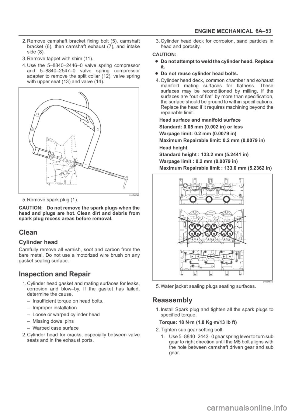
4. Use the 5–8840–2446–0 valve spring compressor
and 5–8840–2547–0 valve spring compressor
adapter to remove the split collar (12), valve spring
with upper seat (13) and valve (14).
014RW042
5. Remove spark plug (1).
CAUTION: Do not remove the spark plugs when the
head and plugs are hot. Clean dirt and debris from
spark plug recess areas before removal.
Clean
Cylinder head
Carefully remove all varnish, soot and carbon from the
bare metal. Do not use a motorized wire brush on any
gasket sealing surface.
Inspection and Repair
1. Cylinder head gasket and mating surfaces for leaks,
corrosion and blow–by. If the gasket has failed,
determine the cause.
– Insufficient torque on head bolts.
– Improper installation
– Loose or warped cylinder head
– Missing dowel pins
– Warped case surface
2. Cylinder head for cracks, especially between valve
seats and in the exhaust ports.3. Cylinder head deck for corrosion, sand particles in
head and porosity.
CAUTION:
Do not attempt to weld the cylinder head. Replace
it.
Do not reuse cylinder head bolts.
4. Cylinder head deck, common chamber and exhaust
manifold mating surfaces for flatness. These
surfaces may be reconditioned by milling. If the
surfaces are “out of flat” by more than specification,
the surface should be ground to within specifications.
Replace the head if it requires machining beyond the
repairable limit.
Head surface and manifold surface
Standard: 0.05 mm (0.002 in) or less
Warpage limit: 0.2 mm (0.0079 in)
Maximum Repairable limit: 0.2 mm (0.0079 in)
Head height
Standard height : 133.2 mm (5.2441 in)
Warpage limit : 0.2 mm (0.0079 in)
Maximum Repairable limit : 133.0 mm (5.2362 in)
011RW019
5. Water jacket sealing plugs seating surfaces.
Reassembly
1. Install Spark plug and tighten all the spark plugs to
specified torque.
Torque: 18 Nꞏm (1.8 Kgꞏm/13 lb ft)
2. Tighten sub gear setting bolt.
1. Use 5–8840–2443–0 gear spring lever to turn sub
gear to right direction until the M5 bolt aligns with
the hole between camshaft driven gear and sub
gear.
Page 1070 of 6000

6C–3
ENGINE FUEL
Adhere to all Notices and Cautions.
All gasoline engines are designed to use only unleaded
gasoline. Unleaded gasoline must be used for proper
emission control system operation.
Its use will also minimize spark plug fouling and extend
engine oil life. Using leaded gasoline can damage the
emission control system and could result in loss of
emission warranty coverage.
All cars are equipped with an Evaporative Emission
Control System. The purpose of the system is to minimize
the escape of fuel vapors to the atmosphere.
Fuel Metering
The Engine Control Module (ECM) is in complete control
of this fuel delivery system during normal driving
conditions.
The intake manifold function, like that of a diesel, is used
only to let air into the engine. The fuel is injected by
separate injectors that are mounted over the intake
manifold.
The Manifold Absolute Pressure (MAP) sensor measures
the changes in the intake manifold pressure which result
from engine load and speed changes, which the MAP
sensor converts to a voltage output.
This sensor generates the voltage to change
corresponding to the flow of the air drawn into the engine.
The changing voltage is transformed into an electric
signal and provided to the ECM.
With receipt of the signals sent from the MAP sensor,
Intake Air Temperature sensor and others, the ECM
determines an appropriate fuel injection pulse width
feeding such information to the fuel injector valves to
effect an appropriate air/fuel ratio.
The Multiport Fuel Injection system utilizes an injection
system where the injectors turn on at every crankshaft
re vol u tion . Th e EC M con tro ls t he in je cto r on tim e so t ha t
the correct amount of fuel is metered depending on
driving conditions.
Two interchangeable “O” rings are used on the injector
that must be replaced when the injectors are removed.
The fuel rail is attached to the top of the intake manifold
and supplies fuel to all the injectors.
Fuel is recirculated through the rail continually while the
engine is running. This removes air and vapors from the
fuel as well as keeping the fuel cool during hot weather
operation.
The fuel pressure control valve that is mounted on the fuel
rail maintains a pressure differential across the injectors
under all operating conditions. It is accomplished by
controlling the amount of fuel that is recirculated back to
the fuel tank based on engine demand.
See Section “Driveability and Emission” for more
information and diagnosis.