1998 OPEL FRONTERA lock
[x] Cancel search: lockPage 1062 of 6000
ENGINE COOLING6B–9
Radiator
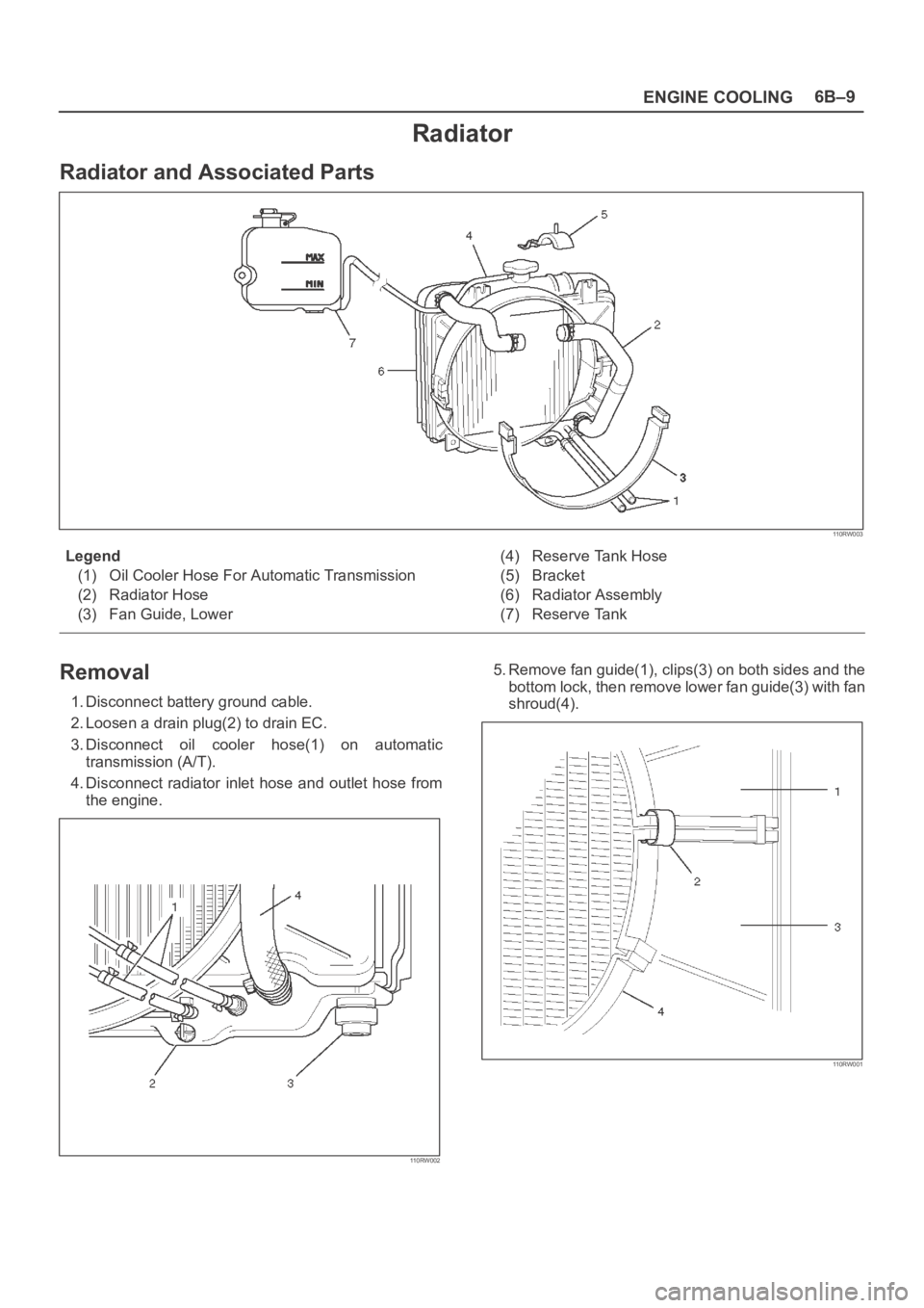
Radiator and Associated Parts
110RW003
Legend
(1) Oil Cooler Hose For Automatic Transmission
(2) Radiator Hose
(3) Fan Guide, Lower(4) Reserve Tank Hose
(5) Bracket
(6) Radiator Assembly
(7) Reserve Tank
Removal
1. Disconnect battery ground cable.
2. Loosen a drain plug(2) to drain EC.
3. Disconnect oil cooler hose(1) on automatic
transmission (A/T).
4. Disconnect radiator inlet hose and outlet hose from
the engine.
110RW002
5. Remove fan guide(1), clips(3) on both sides and the
bottom lock, then remove lower fan guide(3) with fan
shroud(4).
110RW001
Page 1068 of 6000
6C–1
ENGINE FUEL
ENGINE
ENGINE FUEL
CONTENTS
Service Precaution 6C–1. . . . . . . . . . . . . . . . . . . . . .
General Description 6C–2. . . . . . . . . . . . . . . . . . . . .
Fuel Metering 6C–3. . . . . . . . . . . . . . . . . . . . . . . . . . .
Fuel Filter 6C–4. . . . . . . . . . . . . . . . . . . . . . . . . . . . . .
Fuel Filter and Associated Parts 6C–4. . . . . . . . .
Removal 6C–4. . . . . . . . . . . . . . . . . . . . . . . . . . . . .
Inspection 6C–4. . . . . . . . . . . . . . . . . . . . . . . . . . . .
Installation 6C–5. . . . . . . . . . . . . . . . . . . . . . . . . . . .
Inspection 6C–5. . . . . . . . . . . . . . . . . . . . . . . . . . . .
In–Tank Fuel Filter 6C–5. . . . . . . . . . . . . . . . . . . . .
Fuel Pump Flow Test 6C–5. . . . . . . . . . . . . . . . . . .
Fuel Pump 6C–6. . . . . . . . . . . . . . . . . . . . . . . . . . . . .
Fuel Pump and Associated Parts 6C–6. . . . . . . .
Removal 6C–6. . . . . . . . . . . . . . . . . . . . . . . . . . . . .
Installation 6C–6. . . . . . . . . . . . . . . . . . . . . . . . . . . .
Fuel Pump Relay 6C–7. . . . . . . . . . . . . . . . . . . . . . . .
General Description 6C–7. . . . . . . . . . . . . . . . . . . . .
Fuel Tank 6C–7. . . . . . . . . . . . . . . . . . . . . . . . . . . . . . Fuel Tank and Associated Parts 6C–7. . . . . . . . .
Removal 6C–7. . . . . . . . . . . . . . . . . . . . . . . . . . . . .
Installation 6C–8. . . . . . . . . . . . . . . . . . . . . . . . . . . .
Fuel Tube / Quick – Connect Fittings 6C–8. . . . . . .
Precautions 6C–8. . . . . . . . . . . . . . . . . . . . . . . . . . .
Cautions During Work 6C–8. . . . . . . . . . . . . . . . . .
Removal 6C–8. . . . . . . . . . . . . . . . . . . . . . . . . . . . .
Reuse of Quick–Connector 6C–10. . . . . . . . . . . . . . .
Assembling Advice 6C–10. . . . . . . . . . . . . . . . . . . . . .
Fuel Gauge Unit 6C–11. . . . . . . . . . . . . . . . . . . . . . . .
Fuel Gauge Unit and Associated Parts 6C–11. . .
Removal 6C–11. . . . . . . . . . . . . . . . . . . . . . . . . . . . .
Installation 6C–11. . . . . . . . . . . . . . . . . . . . . . . . . . . .
Fuel Filler Cap 6C–12. . . . . . . . . . . . . . . . . . . . . . . . . .
General Description 6C–12. . . . . . . . . . . . . . . . . . . . .
Inspection 6C–12. . . . . . . . . . . . . . . . . . . . . . . . . . . .
Main Data and Specifications 6C–12. . . . . . . . . . . . .
Service Precaution
WARNING: IF SO EQUIPPED WITH A
SUPPLEMENTAL RESTRAINT SYSTEM (SRS),
REFER TO THE SRS COMPONENT AND WIRING
LOCATION VIEW IN ORDER TO DETERMINE
WHETHER YOU ARE PERFORMING SERVICE ON OR
NEAR THE SRS COMPONENTS OR THE SRS
WIRING. WHEN YOU ARE PERFORMING SERVICE
ON OR NEAR THE SRS COMPONENTS OR THE SRS
WIRING, REFER TO THE SRS SERVICE
INFORMATION. FAILURE TO FOLLOW WARNINGS
COULD RESULT IN POSSIBLE AIR BAG
DEPLOYMENT, PERSONAL INJURY, OR
OTHERWISE UNNEEDED SRS SYSTEM REPAIRS.
CAUTION: Always use the correct fastener in the
proper location. When you replace a fastener, use
ONLY the exact part number for that application.
ISUZU will call out those fasteners that require a
replacement after removal. ISUZU will also call out
the fasteners that require thread lockers or thread
sealant. UNLESS OTHERWISE SPECIFIED, do not
use supplemental coatings (Paints, greases, or other
corrosion inhibitors) on threaded fasteners or
fastener joint interfaces. Generally, such coatings
adversely affect the fastener torque and the joint
clamping force, and may damage the fastener. When
you install fasteners, use the correct tightening
sequence and specifications. Following these
instructions can help you avoid damage to parts and
systems.
Page 1077 of 6000
6C–10
ENGINE FUEL
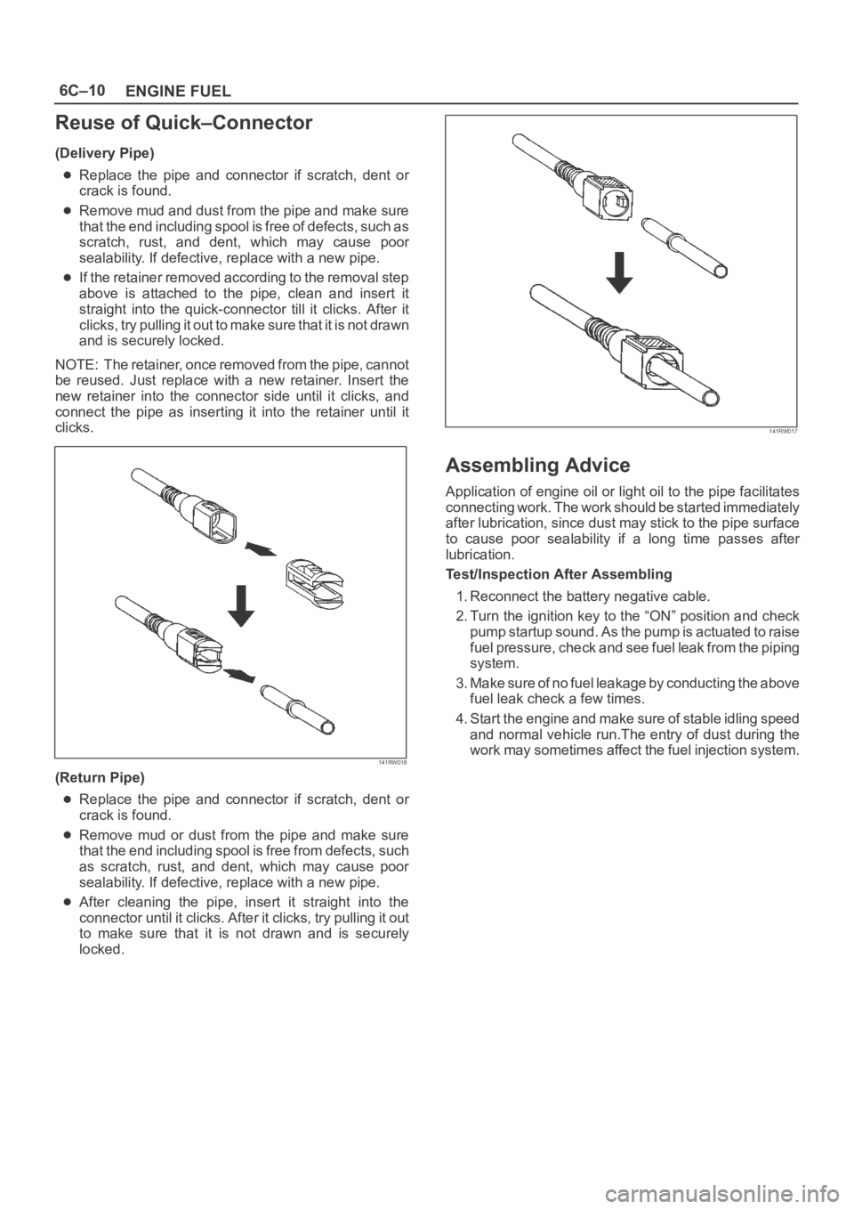
Reuse of Quick–Connector
(Delivery Pipe)
Replace the pipe and connector if scratch, dent or
crack is found.
Remove mud and dust from the pipe and make sure
that the end including spool is free of defects, such as
scratch, rust, and dent, which may cause poor
sealability. If defective, replace with a new pipe.
If the retainer removed according to the removal step
above is attached to the pipe, clean and insert it
straight into the quick-connector till it clicks. After it
clicks, try pulling it out to make sure that it is not drawn
and is securely locked.
NOTE: The retainer, once removed from the pipe, cannot
be reused. Just replace with a new retainer. Insert the
new retainer into the connector side until it clicks, and
connect the pipe as inserting it into the retainer until it
clicks.
141RW018
(Return Pipe)
Replace the pipe and connector if scratch, dent or
crack is found.
Remove mud or dust from the pipe and make sure
that the end including spool is free from defects, such
as scratch, rust, and dent, which may cause poor
sealability. If defective, replace with a new pipe.
After cleaning the pipe, insert it straight into the
connector until it clicks. After it clicks, try pulling it out
to make sure that it is not drawn and is securely
locked.
141RW017
Assembling Advice
Application of engine oil or light oil to the pipe facilitates
connecting work. The work should be started immediately
after lubrication, since dust may stick to the pipe surface
to cause poor sealability if a long time passes after
lubrication.
Test/Inspection After Assembling
1. Reconnect the battery negative cable.
2. Turn the ignition key to the “ON” position and check
pump startup sound. As the pump is actuated to raise
fuel pressure, check and see fuel leak from the piping
system.
3. Make sure of no fuel leakage by conducting the above
fuel leak check a few times.
4. Start the engine and make sure of stable idling speed
and normal vehicle run.The entry of dust during the
work may sometimes affect the fuel injection system.
Page 1080 of 6000
ENGINE ELECTRICAL6D1–1
ENGINE
ENGINE ELECTRICAL
CONTENTS
Service Precaution 6D1–1. . . . . . . . . . . . . . . . . . . . . .
Battery 6D1–2. . . . . . . . . . . . . . . . . . . . . . . . . . . . . . . . .
General Description 6D1–2. . . . . . . . . . . . . . . . . . . .
Diagnosis 6D1–2. . . . . . . . . . . . . . . . . . . . . . . . . . . . .
Battery Charging 6D1–3. . . . . . . . . . . . . . . . . . . . . . Jump Starting 6D1–3. . . . . . . . . . . . . . . . . . . . . . . . .
Battery Removal 6D1–4. . . . . . . . . . . . . . . . . . . . . .
Battery Installation 6D1–4. . . . . . . . . . . . . . . . . . . . .
Main Data and Specifications 6D1–5. . . . . . . . . . .
Service Precaution
WARNING: IF SO EQUIPPED WITH A
SUPPLEMENTAL RESTRAINT SYSTEM (SRS),
REFER TO THE SRS COMPONENT AND WIRING
LOCATION VIEW IN ORDER TO DETERMINE
WHETHER YOU ARE PERFORMING SERVICE ON OR
NEAR THE SRS COMPONENTS OR THE SRS
WIRING. WHEN YOU ARE PERFORMING SERVICE
ON OR NEAR THE SRS COMPONENTS OR THE SRS
WIRING, REFER TO THE SRS SERVICE
INFORMATION. FAILURE TO FOLLOW WARNINGS
COULD RESULT IN POSSIBLE AIR BAG
DEPLOYMENT, PERSONAL INJURY, OR
OTHERWISE UNNEEDED SRS SYSTEM REPAIRS.
CAUTION: Always use the correct fastener in the
proper location. When you replace a fastener, use
ONLY the exact part number for that application.
ISUZU will call out those fasteners that require a
replacement after removal. ISUZU will also call out
the fasteners that require thread lockers or thread
sealant. UNLESS OTHERWISE SPECIFIED, do not
use supplemental coatings (Paints, greases, or other
corrosion inhibitors) on threaded fasteners or
fastener joint interfaces. Generally, such coatings
adversely affect the fastener torque and the joint
clamping force, and may damage the fastener. When
you install fasteners, use the correct tightening
sequence and specifications. Following these
instructions can help you avoid damage to parts and
systems.
Page 1086 of 6000
6D2–1
IGNITION SYSTEM
ENGINE
IGNITION SYSTEM
CONTENTS
Service Precaution 6D2–1. . . . . . . . . . . . . . . . . . . . . .
General Description 6D2–2. . . . . . . . . . . . . . . . . . . . .
Diagnosis 6D2–2. . . . . . . . . . . . . . . . . . . . . . . . . . . . . .
Ignition Coil 6D2–3. . . . . . . . . . . . . . . . . . . . . . . . . . . . .
Removal 6D2–3. . . . . . . . . . . . . . . . . . . . . . . . . . . . .
Inspection and Repair 6D2–3. . . . . . . . . . . . . . . . . .
Installation 6D2–3. . . . . . . . . . . . . . . . . . . . . . . . . . . .
Spark Plug 6D2–4. . . . . . . . . . . . . . . . . . . . . . . . . . . . . Removal 6D2–4. . . . . . . . . . . . . . . . . . . . . . . . . . . . .
Inspection and Repair 6D2–4. . . . . . . . . . . . . . . . . .
Installation 6D2–4. . . . . . . . . . . . . . . . . . . . . . . . . . . .
Crankshaft Angle Sensor 6D2–5. . . . . . . . . . . . . . . . .
Removal 6D2–5. . . . . . . . . . . . . . . . . . . . . . . . . . . . .
Installation 6D2–5. . . . . . . . . . . . . . . . . . . . . . . . . . . .
Main Data and Specifications 6D2–6. . . . . . . . . . . . .
Service Precaution
WARNING: IF SO EQUIPPED WITH A
SUPPLEMENTAL RESTRAINT SYSTEM (SRS),
REFER TO THE SRS COMPONENT AND WIRING
LOCATION VIEW IN ORDER TO DETERMINE
WHETHER YOU ARE PERFORMING SERVICE ON OR
NEAR THE SRS COMPONENTS OR THE SRS
WIRING. WHEN YOU ARE PERFORMING SERVICE
ON OR NEAR THE SRS COMPONENTS OR THE SRS
WIRING, REFER TO THE SRS SERVICE
INFORMATION. FAILURE TO FOLLOW WARNINGS
COULD RESULT IN POSSIBLE AIR BAG
DEPLOYMENT, PERSONAL INJURY, OR
OTHERWISE UNNEEDED SRS SYSTEM REPAIRS.
CAUTION: Always use the correct fastener in the
proper location. When you replace a fastener, use
ONLY the exact part number for that application.
ISUZU will call out those fasteners that require a
replacement after removal. ISUZU will also call out
the fasteners that require thread lockers or thread
sealant. UNLESS OTHERWISE SPECIFIED, do not
use supplemental coatings (Paints, greases, or other
corrosion inhibitors) on threaded fasteners or
fastener joint interfaces. Generally, such coatings
adversely affect the fastener torque and the joint
clamping force, and may damage the fastener. When
you install fasteners, use the correct tightening
sequence and specifications. Following these
instructions can help you avoid damage to parts and
systems.
Page 1090 of 6000
6D2–5
IGNITION SYSTEM
Crankshaft Angle Sensor
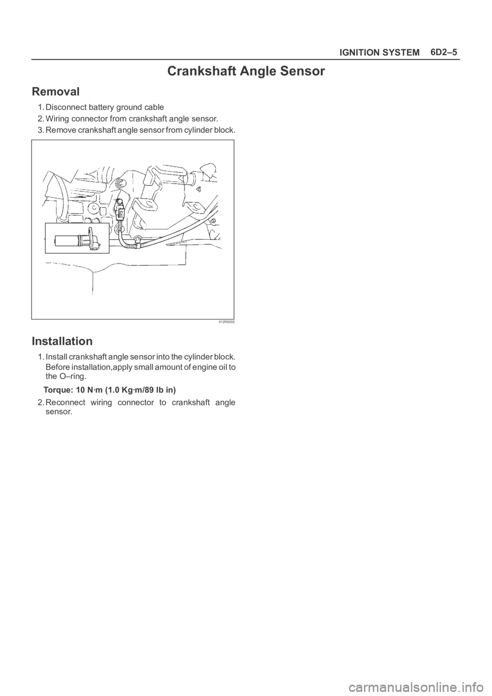
Removal
1. Disconnect battery ground cable
2. Wiring connector from crankshaft angle sensor.
3. Remove crankshaft angle sensor from cylinder block.
012RS008
Installation
1. Install crankshaft angle sensor into the cylinder block.
Before installation,apply small amount of engine oil to
the O–ring.
Torque: 10 Nꞏm (1.0 Kgꞏm/89 lb in)
2. Reconnect wiring connector to crankshaft angle
sensor.
Page 1092 of 6000
6D3–1 STARTING AND CHARGING SYSTEM
ENGINE
STARTING AND CHARGING SYSTEM
CONTENTS
Service Precaution 6D3–1. . . . . . . . . . . . . . . . . . . . . .
Starting System 6D3–2. . . . . . . . . . . . . . . . . . . . . . . . .
General Description 6D3–2. . . . . . . . . . . . . . . . . . . . .
Diagnosis 6D3–4. . . . . . . . . . . . . . . . . . . . . . . . . . . . . .
Starter 6D3–5. . . . . . . . . . . . . . . . . . . . . . . . . . . . . . . . .
Removal 6D3–5. . . . . . . . . . . . . . . . . . . . . . . . . . . . .
Installation 6D3–5. . . . . . . . . . . . . . . . . . . . . . . . . . . .
Disassembled View 6D3–6. . . . . . . . . . . . . . . . . . . .
Disassembly 6D3–7. . . . . . . . . . . . . . . . . . . . . . . . . .
Inspection and Repair 6D3–9. . . . . . . . . . . . . . . . . .
Reassembly 6D3–13. . . . . . . . . . . . . . . . . . . . . . . . . .
Main Data and Specifications 6D3–15. . . . . . . . . . .
Charging System 6D3–18. . . . . . . . . . . . . . . . . . . . . . . . General Description 6D3–18. . . . . . . . . . . . . . . . . . . . .
General On–Vehicle Inspection 6D3–18. . . . . . . . . . .
Generator 6D3–19. . . . . . . . . . . . . . . . . . . . . . . . . . . . . .
Removal 6D3–19. . . . . . . . . . . . . . . . . . . . . . . . . . . . .
Inspection 6D3–19. . . . . . . . . . . . . . . . . . . . . . . . . . . .
Installation 6D3–19. . . . . . . . . . . . . . . . . . . . . . . . . . . .
Disassembled View 6D3–20. . . . . . . . . . . . . . . . . . . .
Disassembly 6D3–21. . . . . . . . . . . . . . . . . . . . . . . . . .
Inspection and Repair 6D3–23. . . . . . . . . . . . . . . . . .
Reassembly 6D3–24. . . . . . . . . . . . . . . . . . . . . . . . . .
Bench Test 6D3–25. . . . . . . . . . . . . . . . . . . . . . . . . . .
Main Data and Specifications 6D3–26. . . . . . . . . . .
Service Precaution
WARNING: IF SO EQUIPPED WITH A
SUPPLEMENTAL RESTRAINT SYSTEM (SRS),
REFER TO THE SRS COMPONENT AND WIRING
LOCATION VIEW IN ORDER TO DETERMINE
WHETHER YOU ARE PERFORMING SERVICE ON OR
NEAR THE SRS COMPONENTS OR THE SRS
WIRING. WHEN YOU ARE PERFORMING SERVICE
ON OR NEAR THE SRS COMPONENTS OR THE SRS
WIRING, REFER TO THE SRS SERVICE
INFORMATION. FAILURE TO FOLLOW WARNINGS
COULD RESULT IN POSSIBLE AIR BAG
DEPLOYMENT, PERSONAL INJURY, OR
OTHERWISE UNNEEDED SRS SYSTEM REPAIRS.
CAUTION: Always use the correct fastener in the
proper location. When you replace a fastener, use
ONLY the exact part number for that application.
ISUZU will call out those fasteners that require a
replacement after removal. ISUZU will also call out
the fasteners that require thread lockers or thread
sealant. UNLESS OTHERWISE SPECIFIED, do not
use supplemental coatings (Paints, greases, or other
corrosion inhibitors) on threaded fasteners or
fastener joint interfaces. Generally, such coatings
adversely affect the fastener torque and the joint
clamping force, and may damage the fastener. When
you install fasteners, use the correct tightening
sequence and specifications. Following these
instructions can help you avoid damage to parts and
systems.
Page 1100 of 6000
6D3–9 STARTING AND CHARGING SYSTEM
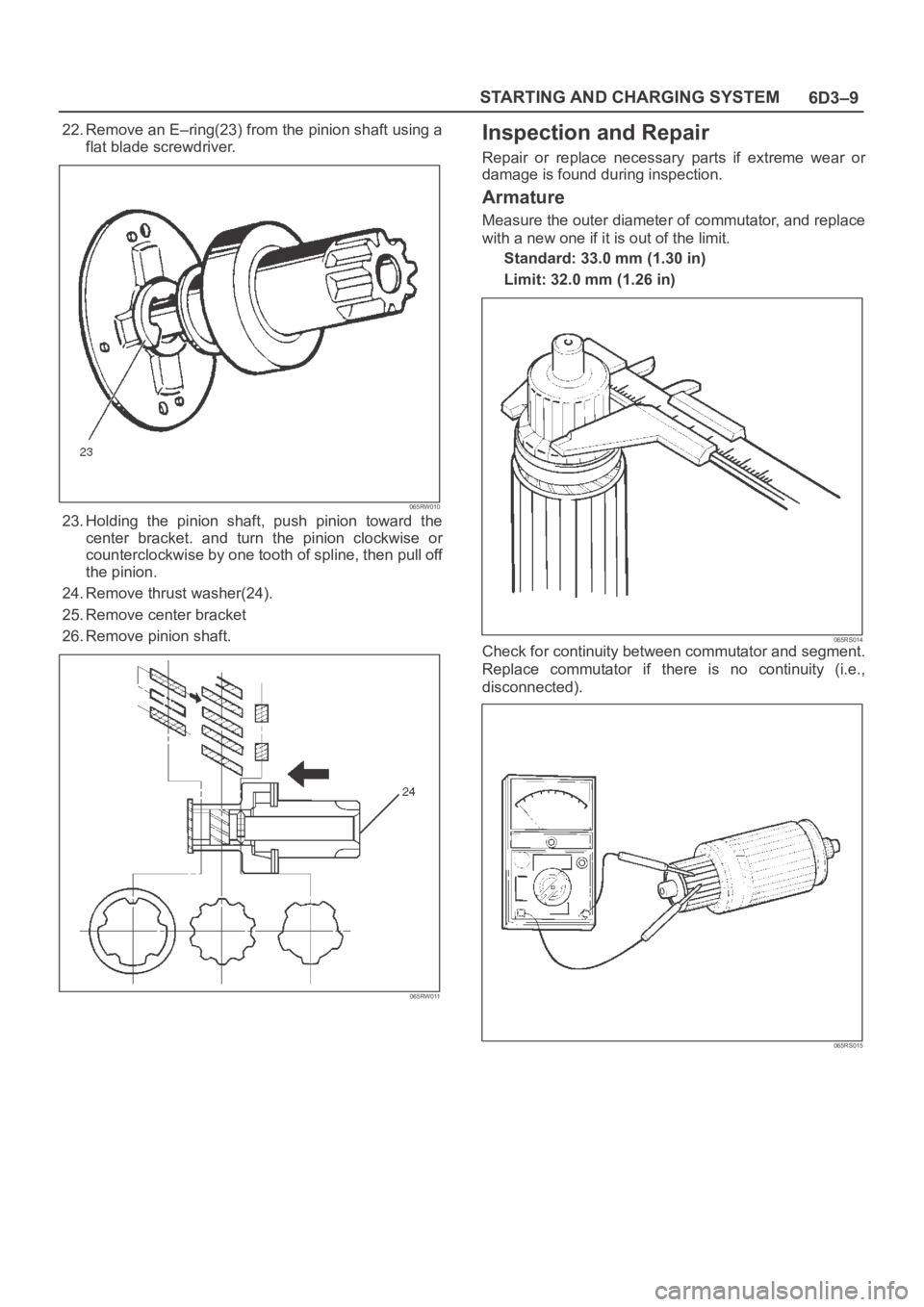
22. Remove an E–ring(23) from the pinion shaft using a
flat blade screwdriver.
065RW010
23. Holding the pinion shaft, push pinion toward the
center bracket. and turn the pinion clockwise or
counterclockwise by one tooth of spline, then pull off
the pinion.
24. Remove thrust washer(24).
25. Remove center bracket
26. Remove pinion shaft.
065RW011
Inspection and Repair
Repair or replace necessary parts if extreme wear or
damage is found during inspection.
Armature
Measure the outer diameter of commutator, and replace
with a new one if it is out of the limit.
Standard: 33.0 mm (1.30 in)
Limit: 32.0 mm (1.26 in)
065RS014Check for continuity between commutator and segment.
Replace commutator if there is no continuity (i.e.,
disconnected).
065RS015