1998 OPEL FRONTERA lock
[x] Cancel search: lockPage 1041 of 6000
6A–85
ENGINE MECHANICAL
Cylinder Block
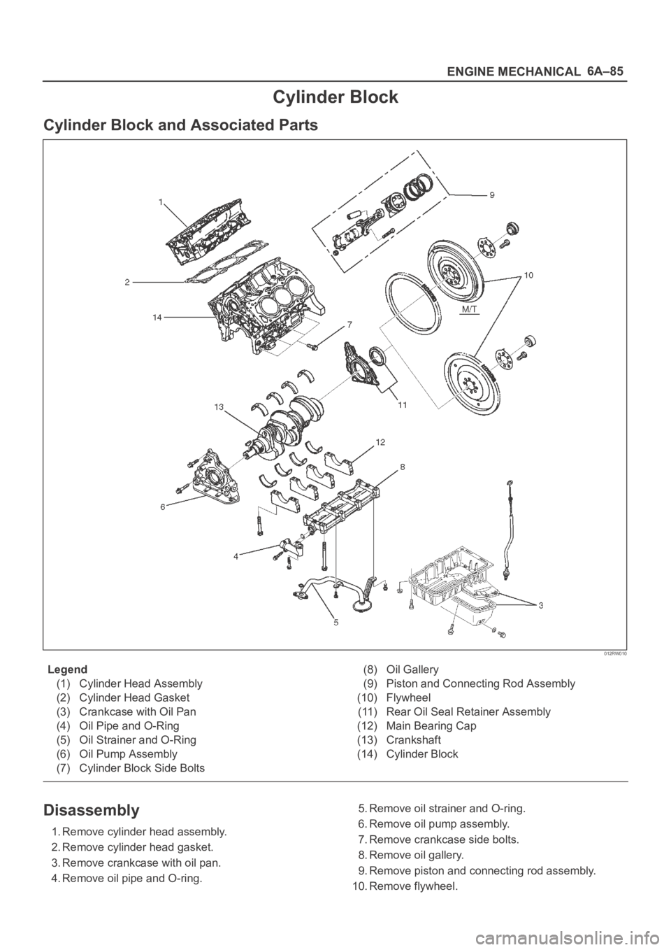
Cylinder Block and Associated Parts
012RW010
Legend
(1) Cylinder Head Assembly
(2) Cylinder Head Gasket
(3) Crankcase with Oil Pan
(4) Oil Pipe and O-Ring
(5) Oil Strainer and O-Ring
(6) Oil Pump Assembly
(7) Cylinder Block Side Bolts(8) Oil Gallery
(9) Piston and Connecting Rod Assembly
(10) Flywheel
(11) Rear Oil Seal Retainer Assembly
(12) Main Bearing Cap
(13) Crankshaft
(14) Cylinder Block
Disassembly
1. Remove cylinder head assembly.
2. Remove cylinder head gasket.
3. Remove crankcase with oil pan.
4. Remove oil pipe and O-ring.5. Remove oil strainer and O-ring.
6. Remove oil pump assembly.
7. Remove crankcase side bolts.
8. Remove oil gallery.
9. Remove piston and connecting rod assembly.
10. Remove flywheel.
Page 1042 of 6000
6A–86
ENGINE MECHANICAL
11. Remove rear oil seal retainer assembly.
12. Remove main bearing cap.
13. Remove crankshaft.
14. Remove cylinder block.
Inspection and Repair
1. Remove the cylinder head gasket and any other
material adhering to the upper surface of the cylinder
block. Be very careful not to allow any material to
accidentally drop into the cylinder block. Be very
careful not to scratch the cylinder block.
2. Carefully remove the oil pump, rear oil seal retainer,
and crankcase assembly installation surface seal.
3. Wipe the cylinder block clean.
4. Visually inspect the cylinder block. If necessary, use a
flaw detector to perform a dye penetrate and
hydraulic (or air pressure) test. If cracking or other
damage is discovered, the cylinder block must either
be repaired or replaced.
Flatness
1. Using a straight–edge and feeler gauge, check that
the upper surface of the cylinder block is not warped.
CAUTION: Be very careful not to allow any material
to accidentally drop into the upper surface of the
cylinder block. Be very careful not to scratch the
upper surface of the cylinder block.
2. The cylinder block must be reground or replaced if the
warpage exceeds the limit.
Warpage
Limit : 0.15 mm (0.0059 in)
Maximum repairable limit: 0.15 mm (0.0059 in)
012RS004
Cylinder Bore
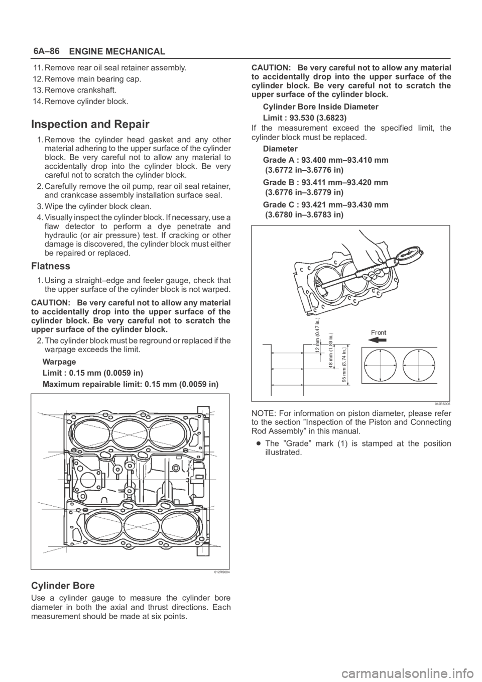
Use a cylinder gauge to measure the cylinder bore
diameter in both the axial and thrust directions. Each
measurement should be made at six points.CAUTION: Be very careful not to allow any material
to accidentally drop into the upper surface of the
cylinder block. Be very careful not to scratch the
upper surface of the cylinder block.
Cylinder Bore Inside Diameter
Limit : 93.530 (3.6823)
If the measurement exceed the specified limit, the
cylinder block must be replaced.
Diameter
Grade A : 93.400 mm–93.410 mm
(3.6772 in–3.6776 in)
Grade B : 93.411 mm–93.420 mm
(3.6776 in–3.6779 in)
Grade C : 93.421 mm–93.430 mm
(3.6780 in–3.6783 in)
012RS005
NOTE: For information on piston diameter, please refer
to the section ”Inspection of the Piston and Connecting
Rod Assembly” in this manual.
The ”Grade” mark (1) is stamped at the position
illustrated.
Page 1043 of 6000
6A–87
ENGINE MECHANICAL
012RS006
Reassembly
1. Install cylinder block.
2. Install crankshaft.
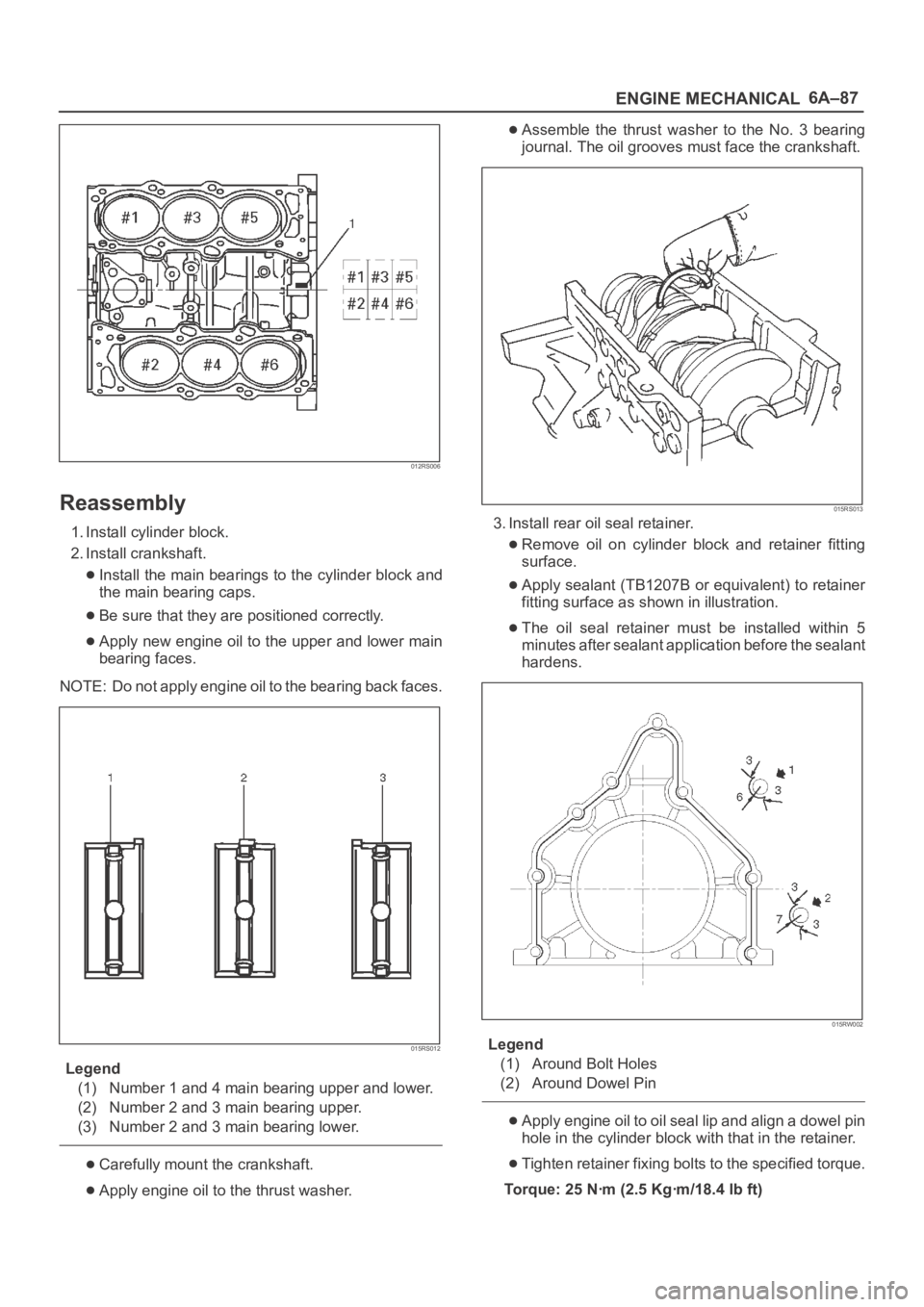
Install the main bearings to the cylinder block and
the main bearing caps.
Be sure that they are positioned correctly.
Apply new engine oil to the upper and lower main
bearing faces.
NOTE: Do not apply engine oil to the bearing back faces.
015RS012
Legend
(1) Number 1 and 4 main bearing upper and lower.
(2) Number 2 and 3 main bearing upper.
(3) Number 2 and 3 main bearing lower.
Carefully mount the crankshaft.
Apply engine oil to the thrust washer.
Assemble the thrust washer to the No. 3 bearing
journal. The oil grooves must face the crankshaft.
015RS013
3. Install rear oil seal retainer.
Remove oil on cylinder block and retainer fitting
surface.
Apply sealant (TB1207B or equivalent) to retainer
fitting surface as shown in illustration.
The oil seal retainer must be installed within 5
minutes after sealant application before the sealant
hardens.
015RW002
Legend
(1) Around Bolt Holes
(2) Around Dowel Pin
Apply engine oil to oil seal lip and align a dowel pin
hole in the cylinder block with that in the retainer.
Tighten retainer fixing bolts to the specified torque.
Torque: 25 Nꞏm (2.5 Kgꞏm/18.4 lb ft)
Page 1044 of 6000
6A–88
ENGINE MECHANICAL
015RW001
4. Install flywheel
1. Thoroughly clean and remove the oil from the
threads of crankshaft.
2. Remove the oil from the crankshaft and flywheel
mounting faces.
3. Mount the flywheel on the crankshaft and then
install the washer.
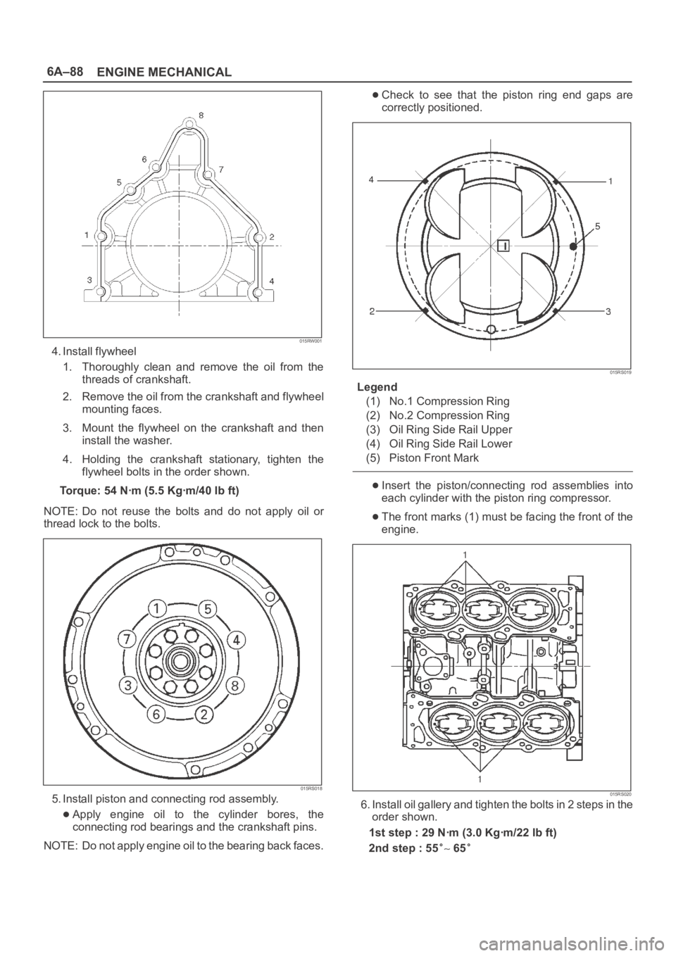
4. Holding the crankshaft stationary, tighten the
flywheel bolts in the order shown.
Torque: 54 Nꞏm (5.5 Kgꞏm/40 lb ft)
NOTE: Do not reuse the bolts and do not apply oil or
thread lock to the bolts.
015RS018
5. Install piston and connecting rod assembly.
Apply engine oil to the cylinder bores, the
connecting rod bearings and the crankshaft pins.
NOTE: Do not apply engine oil to the bearing back faces.
Check to see that the piston ring end gaps are
correctly positioned.
015RS019
Legend
(1) No.1 Compression Ring
(2) No.2 Compression Ring
(3) Oil Ring Side Rail Upper
(4) Oil Ring Side Rail Lower
(5) Piston Front Mark
Insert the piston/connecting rod assemblies into
each cylinder with the piston ring compressor.
The front marks (1) must be facing the front of the
engine.
015RS020
6. Install oil gallery and tighten the bolts in 2 steps in the
order shown.
1st step : 29 Nꞏm (3.0 Kgꞏm/22 lb ft)
2nd step : 55
65
Page 1045 of 6000
6A–89
ENGINE MECHANICAL
012RS007
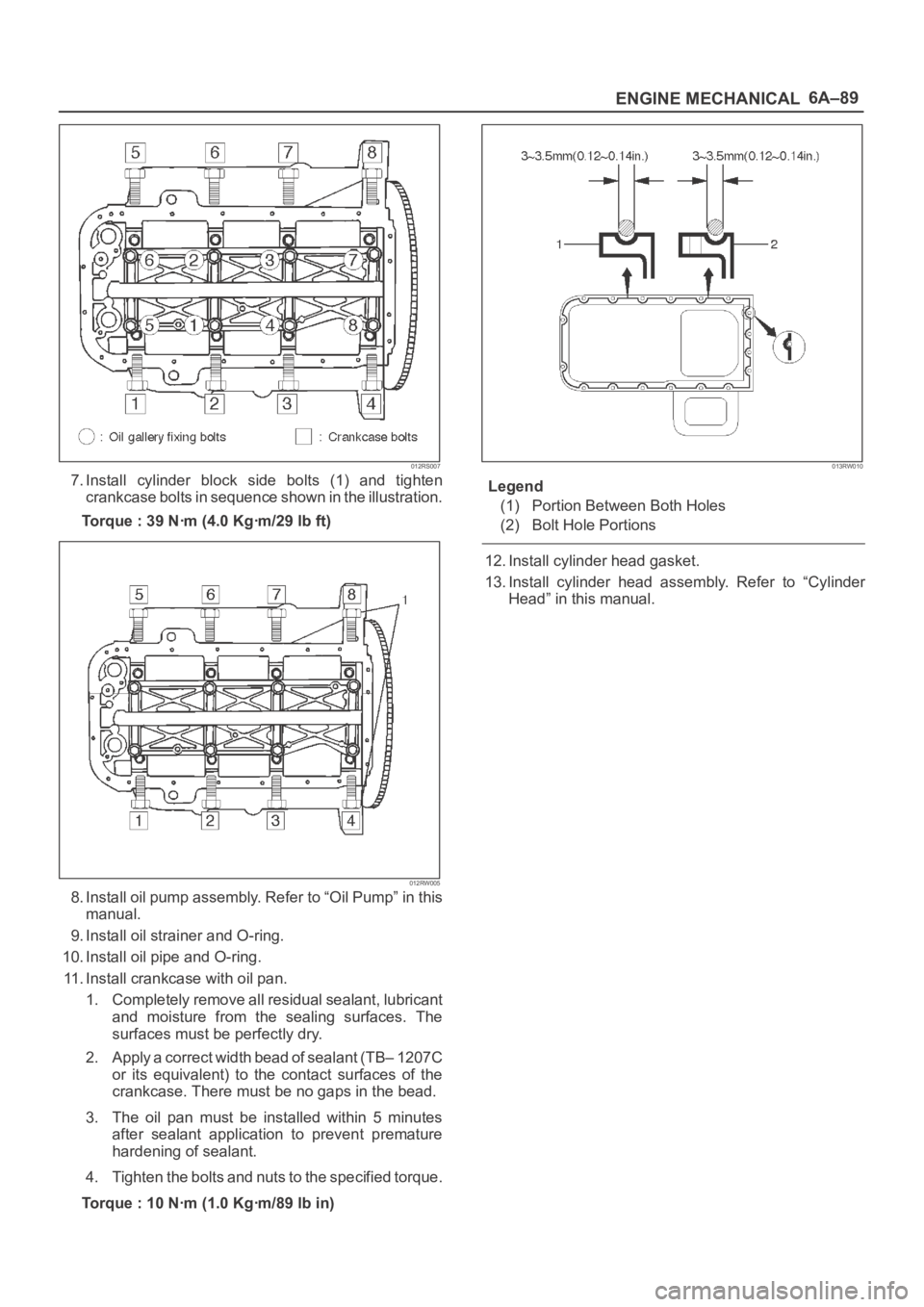
7. Install cylinder block side bolts (1) and tighten
crankcase bolts in sequence shown in the illustration.
Torque : 39 Nꞏm (4.0 Kgꞏm/29 lb ft)
012RW005
8. Install oil pump assembly. Refer to “Oil Pump” in this
manual.
9. Install oil strainer and O-ring.
10. Install oil pipe and O-ring.
11. Install crankcase with oil pan.
1. Completely remove all residual sealant, lubricant
and moisture from the sealing surfaces. The
surfaces must be perfectly dry.
2. Apply a correct width bead of sealant (TB– 1207C
or its equivalent) to the contact surfaces of the
crankcase. There must be no gaps in the bead.
3. The oil pan must be installed within 5 minutes
after sealant application to prevent premature
hardening of sealant.
4. Tighten the bolts and nuts to the specified torque.
Torque : 10 Nꞏm (1.0 Kgꞏm/89 lb in)
013RW010
Legend
(1) Portion Between Both Holes
(2) Bolt Hole Portions
12. Install cylinder head gasket.
13. Install cylinder head assembly. Refer to “Cylinder
Head” in this manual.
Page 1054 of 6000
ENGINE COOLING6B–1
ENGINE
ENGINE COOLING
CONTENTS
Service Precaution 6B–1. . . . . . . . . . . . . . . . . . . . . .
General Description 6B–2. . . . . . . . . . . . . . . . . . . . .
Diagnosis 6B–5. . . . . . . . . . . . . . . . . . . . . . . . . . . . . .
Draining and Refilling Cooling System 6B–6. . . . .
Water Pump 6B–7. . . . . . . . . . . . . . . . . . . . . . . . . . . .
Water Pump and Associated Parts 6B–7. . . . . . .
Removal 6B–7. . . . . . . . . . . . . . . . . . . . . . . . . . . . .
Inspection 6B–7. . . . . . . . . . . . . . . . . . . . . . . . . . . .
Installation 6B–7. . . . . . . . . . . . . . . . . . . . . . . . . . . .
Thermostat 6B–8. . . . . . . . . . . . . . . . . . . . . . . . . . . . .
Thermostat and Associated Parts 6B–8. . . . . . . .
Removal 6B–8. . . . . . . . . . . . . . . . . . . . . . . . . . . . .
Inspection 6B–8. . . . . . . . . . . . . . . . . . . . . . . . . . . . Installation 6B–8. . . . . . . . . . . . . . . . . . . . . . . . . . . .
Radiator 6B–9. . . . . . . . . . . . . . . . . . . . . . . . . . . . . . .
Radiator and Associated Parts 6B–9. . . . . . . . . .
Removal 6B–9. . . . . . . . . . . . . . . . . . . . . . . . . . . . .
Inspection 6B–10. . . . . . . . . . . . . . . . . . . . . . . . . . . .
Installation 6B–11. . . . . . . . . . . . . . . . . . . . . . . . . . . .
Drive Belt and Cooling Fan 6B–12. . . . . . . . . . . . . . .
Drive Belt and Associated Parts 6B–12. . . . . . . . .
Inspection 6B–12. . . . . . . . . . . . . . . . . . . . . . . . . . . .
Installation 6B–12. . . . . . . . . . . . . . . . . . . . . . . . . . . .
Main Data and Specifications 6B–13. . . . . . . . . . . . .
Special Tool 6B–14. . . . . . . . . . . . . . . . . . . . . . . . . . . .
Service Precaution
WARNING: IF SO EQUIPPED WITH A
SUPPLEMENTAL RESTRAINT SYSTEM (SRS),
REFER TO THE SRS COMPONENT AND WIRING
LOCATION VIEW IN ORDER TO DETERMINE
WHETHER YOU ARE PERFORMING SERVICE ON OR
NEAR THE SRS COMPONENTS OR THE SRS
WIRING. WHEN YOU ARE PERFORMING SERVICE
ON OR NEAR THE SRS COMPONENTS OR THE SRS
WIRING, REFER TO THE SRS SERVICE
INFORMATION. FAILURE TO FOLLOW WARNINGS
COULD RESULT IN POSSIBLE AIR BAG
DEPLOYMENT, PERSONAL INJURY, OR
OTHERWISE UNNEEDED SRS SYSTEM REPAIRS.
CAUTION: Always use the correct fastener in the
proper location. When you replace a fastener, use
ONLY the exact part number for that application.
ISUZU will call out those fasteners that require a
replacement after removal. ISUZU will also call out
the fasteners that require thread lockers or thread
sealant. UNLESS OTHERWISE SPECIFIED, do not
use supplemental coatings (Paints, greases, or other
corrosion inhibitors) on threaded fasteners or
fastener joint interfaces. Generally, such coatings
adversely affect the fastener torque and the joint
clamping force, and may damage the fastener. When
you install fasteners, use the correct tightening
sequence and specifications. Following these
instructions can help you avoid damage to parts and
systems.
Page 1055 of 6000
6B–2
ENGINE COOLING
General Description
030RW001
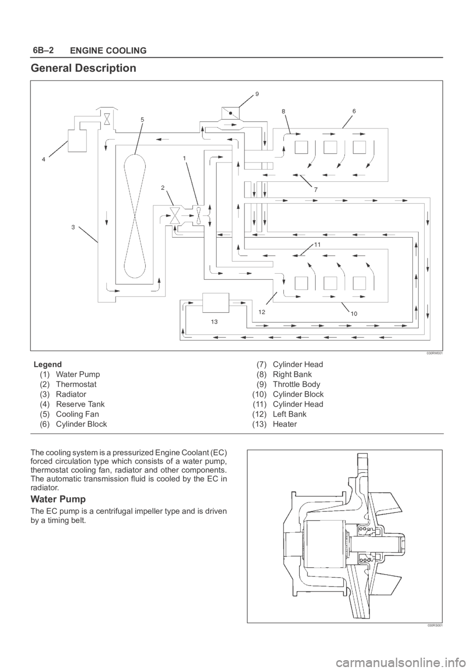
Legend
(1) Water Pump
(2) Thermostat
(3) Radiator
(4) Reserve Tank
(5) Cooling Fan
(6) Cylinder Block(7) Cylinder Head
(8) Right Bank
(9) Throttle Body
(10) Cylinder Block
(11) Cylinder Head
(12) Left Bank
(13) Heater
The cooling system is a pressurized Engine Coolant (EC)
forced circulation type which consists of a water pump,
thermostat cooling fan, radiator and other components.
The automatic transmission fluid is cooled by the EC in
radiator.
Water Pump
The EC pump is a centrifugal impeller type and is driven
by a timing belt.
030RS001
Page 1059 of 6000
6B–6
ENGINE COOLING
Draining and Refilling Cooling
System
Before draining the cooling system, inspect the system
and perform any necessary service to ensure that it is
clean, does not leak and is in proper working order. The
engine coolant (EC) level should be between the “MIN”
and “MAX” lines of reserve tank when the engine is cold.
If low, check for leakage and add EC up to the “MAX” line.
There should not be any excessive deposit of rust or
scales around the radiator cap or radiator filler hole, and
the EC should also be free from oil.
Replace the EC if excessively dirty.
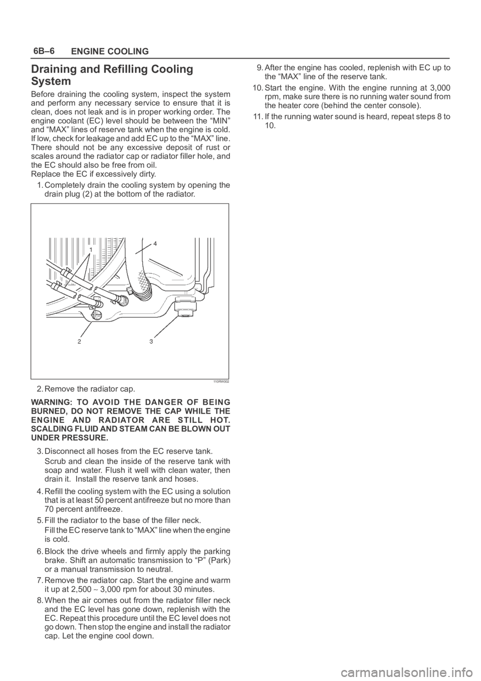
1. Completely drain the cooling system by opening the
drain plug (2) at the bottom of the radiator.
110RW002
2. Remove the radiator cap.
WARNING: TO AVOID THE DANGER OF BEING
BURNED, DO NOT REMOVE THE CAP WHILE THE
ENGINE AND RADIATOR ARE STILL HOT.
SCALDING FLUID AND STEAM CAN BE BLOWN OUT
UNDER PRESSURE.
3. Disconnect all hoses from the EC reserve tank.
Scrub and clean the inside of the reserve tank with
soap and water. Flush it well with clean water, then
drain it. Install the reserve tank and hoses.
4. Refill the cooling system with the EC using a solution
that is at least 50 percent antifreeze but no more than
70 percent antifreeze.
5. Fill the radiator to the base of the filler neck.
Fill the EC reserve tank to “MAX” line when the engine
is cold.
6. Block the drive wheels and firmly apply the parking
brake. Shift an automatic transmission to “P” (Park)
or a manual transmission to neutral.
7. Remove the radiator cap. Start the engine and warm
it up at 2,500
3,000 rpm for about 30 minutes.
8. When the air comes out from the radiator filler neck
and the EC level has gone down, replenish with the
EC. Repeat this procedure until the EC level does not
go down. Then stop the engine and install the radiator
cap. Let the engine cool down.9. After the engine has cooled, replenish with EC up to
the “MAX” line of the reserve tank.
10. Start the engine. With the engine running at 3,000
rpm, make sure there is no running water sound from
the heater core (behind the center console).
11. If the running water sound is heard, repeat steps 8 to
10.