Page 3477 of 6000
SUPPLEMENTAL RESTRAINT SYSTEM 9J–40
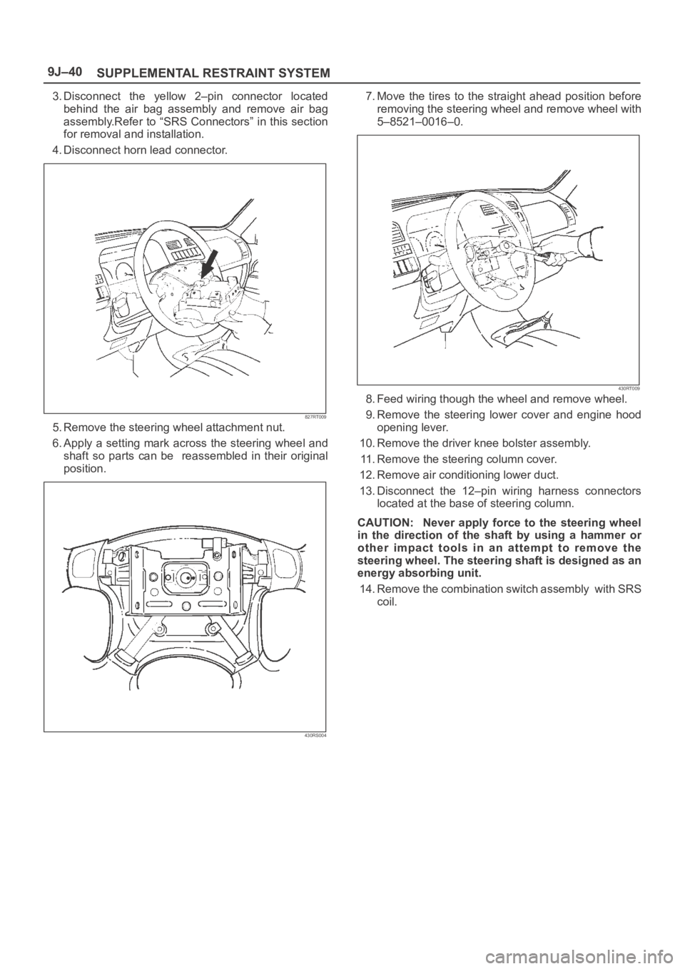
3. Disconnect the yellow 2–pin connector located
behind the air bag assembly and remove air bag
assembly.Refer to “SRS Connectors” in this section
for removal and installation.
4. Disconnect horn lead connector.
827RT009
5. Remove the steering wheel attachment nut.
6. Apply a setting mark across the steering wheel and
shaft so parts can be reassembled in their original
position.
430RS004
7. Move the tires to the straight ahead position before
removing the steering wheel and remove wheel with
5–8521–0016–0.
430RT009
8. Feed wiring though the wheel and remove wheel.
9. Remove the steering lower cover and engine hood
opening lever.
10. Remove the driver knee bolster assembly.
11. Remove the steering column cover.
12. Remove air conditioning lower duct.
13. Disconnect the 12–pin wiring harness connectors
located at the base of steering column.
CAUTION: Never apply force to the steering wheel
in the direction of the shaft by using a hammer or
other impact tools in an attempt to remove the
steering wheel. The steering shaft is designed as an
energy absorbing unit.
14. Remove the combination switch assembly with SRS
coil.
Page 3478 of 6000
SUPPLEMENTAL RESTRAINT SYSTEM9J–41
Installation
1. Install the combination switch assembly with SRS
coil.
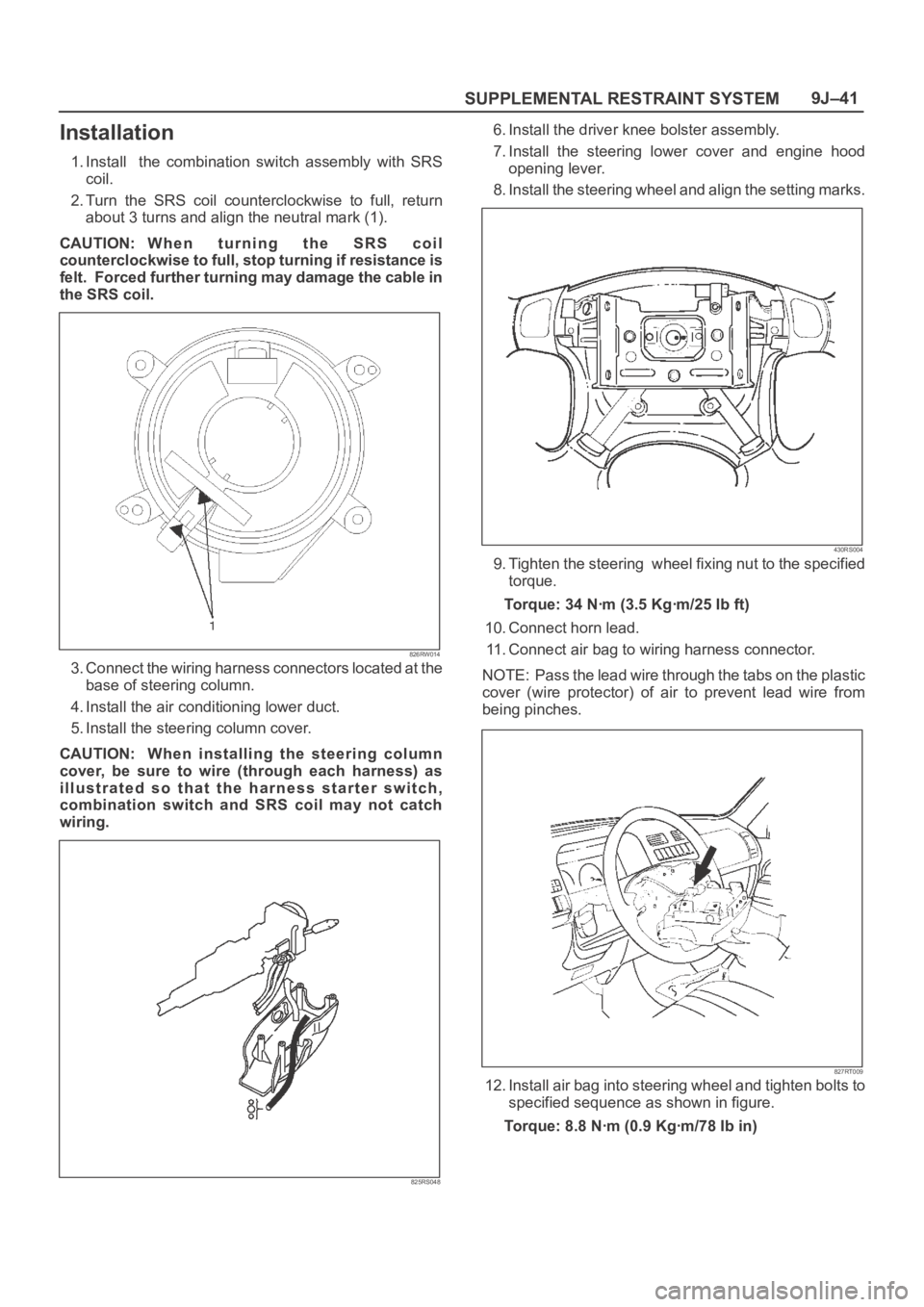
2. Turn the SRS coil counterclockwise to full, return
about 3 turns and align the neutral mark (1).
CAUTION: W h e n t u r n i n g t h e S R S c o i l
counterclockwise to full, stop turning if resistance is
felt. Forced further turning may damage the cable in
the SRS coil.
826RW014
3. Connect the wiring harness connectors located at the
base of steering column.
4. Install the air conditioning lower duct.
5. Install the steering column cover.
CAUTION: When installing the steering column
cover, be sure to wire (through each harness) as
illustrated so that the harness starter switch,
combination switch and SRS coil may not catch
wiring.
825RS048
6. Install the driver knee bolster assembly.
7. Install the steering lower cover and engine hood
opening lever.
8. Install the steering wheel and align the setting marks.
430RS004
9. Tighten the steering wheel fixing nut to the specified
torque.
Torque: 34 Nꞏm (3.5 Kgꞏm/25 Ib ft)
10. Connect horn lead.
11. Connect air bag to wiring harness connector.
NOTE: Pass the lead wire through the tabs on the plastic
cover (wire protector) of air to prevent lead wire from
being pinches.
827RT009
12. Install air bag into steering wheel and tighten bolts to
specified sequence as shown in figure.
Torque: 8.8 Nꞏm (0.9 Kgꞏm/78 Ib in)
Page 3482 of 6000
SUPPLEMENTAL RESTRAINT SYSTEM9J–45
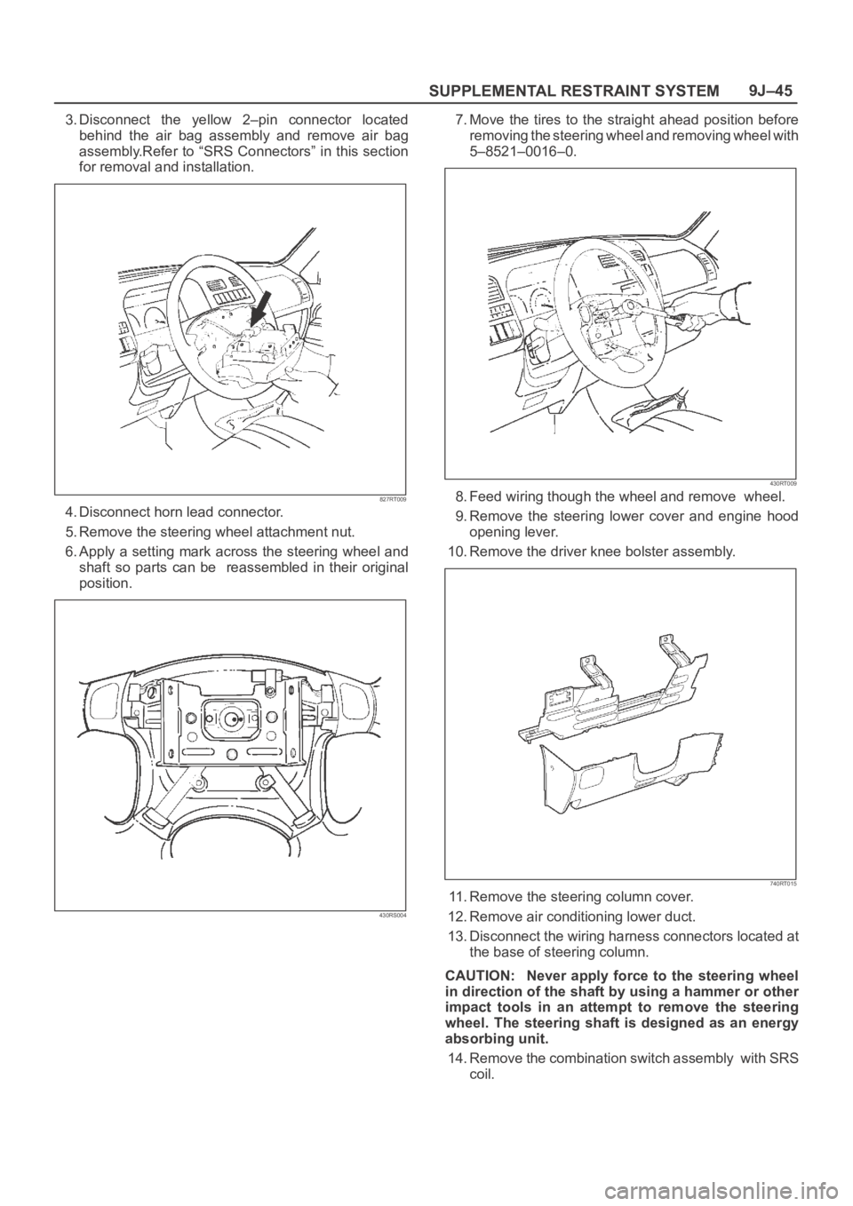
3. Disconnect the yellow 2–pin connector located
behind the air bag assembly and remove air bag
assembly.Refer to “SRS Connectors” in this section
for removal and installation.
827RT009
4. Disconnect horn lead connector.
5. Remove the steering wheel attachment nut.
6. Apply a setting mark across the steering wheel and
shaft so parts can be reassembled in their original
position.
430RS004
7. Move the tires to the straight ahead position before
removing the steering wheel and removing wheel with
5–8521–0016–0.
430RT009
8. Feed wiring though the wheel and remove wheel.
9. Remove the steering lower cover and engine hood
opening lever.
10. Remove the driver knee bolster assembly.
740RT015
11. Remove the steering column cover.
12. Remove air conditioning lower duct.
13. Disconnect the wiring harness connectors located at
the base of steering column.
CAUTION: Never apply force to the steering wheel
in direction of the shaft by using a hammer or other
impact tools in an attempt to remove the steering
wheel. The steering shaft is designed as an energy
absorbing unit.
14. Remove the combination switch assembly with SRS
coil.
Page 3485 of 6000
SUPPLEMENTAL RESTRAINT SYSTEM 9J–48
Passenger Air Bag Assembly
Service Precautions
WARNING: SAFETY PRECAUTIONS MUST BE
FOLLOWED WHEN HANDLING A DEPLOYED AIR
BAG ASSEMBLY. AFTER DEPLOYMENT, THE AIR
BAG ASSEMBLY SURFACE MAY CONTAIN A SMALL
AMOUNT OF SODIUM HYDROXIDE, A BY–PRODUCT
OF THE DEPLOYMENT REACTION, THAT IS
IRRITATING TO THE SKIN AND EYES. MOST OF THE
POWER ON THE AIR BAG ASSEMBLY IS
HARMLESS. AS A PRECAUTION, WEAR GLOVES
AND SAFETY GLASSES WHEN HANDLING A
DEPLOYED AIR BAG ASSEMBLY, AND WASH YOUR
HANDS WITH MILD SOAP AND WATER
AFTERWARDS.
WARNING: WHEN CARRYING A LIVE AIR BAG
ASSEMBLY, MAKE SURE THE BAG AND TRIM
COVER ARE POINTED AWAY FROM YOU. NEVER
CARRY AIR BAG ASSEMBLY BY THE WIRES OR
CONNECTOR ON THE UNDERSIDE OF MODULE. IN
THE CASE OF AN ACCIDENTAL DEPLOYMENT, THE
BAG WILL THEN DEPLOY WITH MINIMAL CHANCE
OF INJURY. WHEN PLACING ALIVE AIR BAG
ASSEMBLY ON A BENCH OR OTHER SURFACE,
ALWAYS FACE BAG AND RIM COVER UP, AWAY
FROM THE SURFACE. NEVER REST A STEERING
COLUMN ASSEMBLY ON THE STEERING WHEEL
WITH THE AIR BAG ASSEMBLY FACE DOWN AND
COLUMN VERTICAL. THIS IS NECESSARY SO THAT
A FREE SPACE IS PROVIDED TO ALLOW THE AIR
BAG ASSEMBLY TO EXPAND IN THE UNLIKELY
EVENT OF ACCIDENTAL DEPLOYMENT.
OTHERWISE, PERSONAL INJURY COULD RESULT.
NOTE: IN THE EVENT DEPLOYMENT HAS
OCCURRED, INSPECT COIL ASSEMBLY WIRE FOR
ANY SIGNS OF SCORCHING, MELTING OR ANY
OTHER DAMAGE DUE TO EXCESSIVE HEAT. IF THE
COIL HAS BEEN DAMAGED, REPLACE IT.
Removal
827RS001
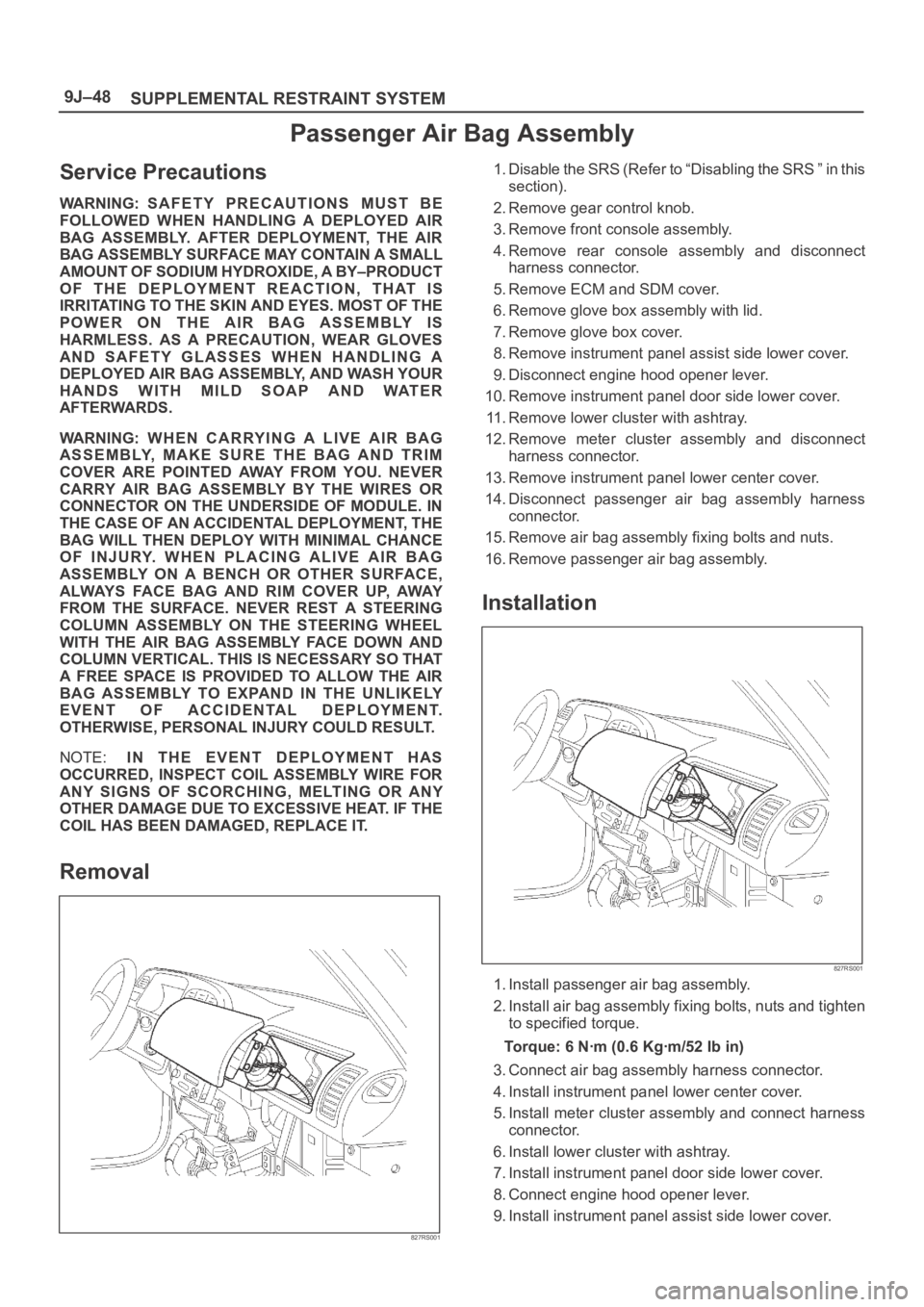
1. Disable the SRS (Refer to “Disabling the SRS ” in this
section).
2. Remove gear control knob.
3. Remove front console assembly.
4. Remove rear console assembly and disconnect
harness connector.
5. Remove ECM and SDM cover.
6. Remove glove box assembly with lid.
7. Remove glove box cover.
8. Remove instrument panel assist side lower cover.
9. Disconnect engine hood opener lever.
10. Remove instrument panel door side lower cover.
11. Remove lower cluster with ashtray.
12. Remove meter cluster assembly and disconnect
harness connector.
13. Remove instrument panel lower center cover.
14. Disconnect passenger air bag assembly harness
connector.
15. Remove air bag assembly fixing bolts and nuts.
16. Remove passenger air bag assembly.
Installation
827RS001
1. Install passenger air bag assembly.
2. Install air bag assembly fixing bolts, nuts and tighten
to specified torque.
Torque: 6 Nꞏm (0.6 Kgꞏm/52 Ib in)
3. Connect air bag assembly harness connector.
4. Install instrument panel lower center cover.
5. Install meter cluster assembly and connect harness
connector.
6. Install lower cluster with ashtray.
7. Install instrument panel door side lower cover.
8. Connect engine hood opener lever.
9. Install instrument panel assist side lower cover.
Page 3566 of 6000
PAGE BACK PAGE NEXT
THIS MALUAL INCLUDES THE FOLLOWING SECTIONS:
6VD1/6VE1
SECTION No. CONTRNTS
6A ENGINE MECHANICAL
6B ENGINE COOLING
6C ENGINE FUEL
6D1 ENGINE ELECTRICAL
6D2 IGNITION SYSTEM
6D3 STARTING AND CHARGING SYSTEM
6E ENGINE DRIVEABILITY AND EMISSIONS
6F ENGINE EXHAUST
6G ENGINE LUBRICATION
6H ENGINE SPEED CONTROL SYSTEM
6J INDUCTION
HOME
6A
6B
6C
6D1
6D2
6D3
6E
6F
6G
6H
6J
Page 3567 of 6000
PAGE BACK PAGE NEXT
4JG2
4JX1 SECTION No. CONTRNTS
00 SERVICE INFORMATION
6A ENGINE MECHANICAL
6A2 4JG2-NA / 4JG2-TURBO ENGINE
6B ENGINE COOLING
6C FUEL SYSTEM
6D ENGINE ELECTRICAL
6E -
6F EXHAUST
6G -
SECTION No. CONTRNTS
6A ENGINE MECHANICAL
6B ENGINE COOLING
6C ENGINE FUEL
6D ENGINE ELECTRICAL
6E ENGINE DRIVEABILITY AND EMISSIONS
6F ENGINE EXHAUST
6G ENGINE LUBRICATION
6H ENGINE SPEED CONTROL
6J INDUCTION
HOME
00
6A
6A2
6B
6C
6D
6E
6F
6G
6A
6B
6C
6D
6E
6F
6G
6H
6J
Page 3701 of 6000
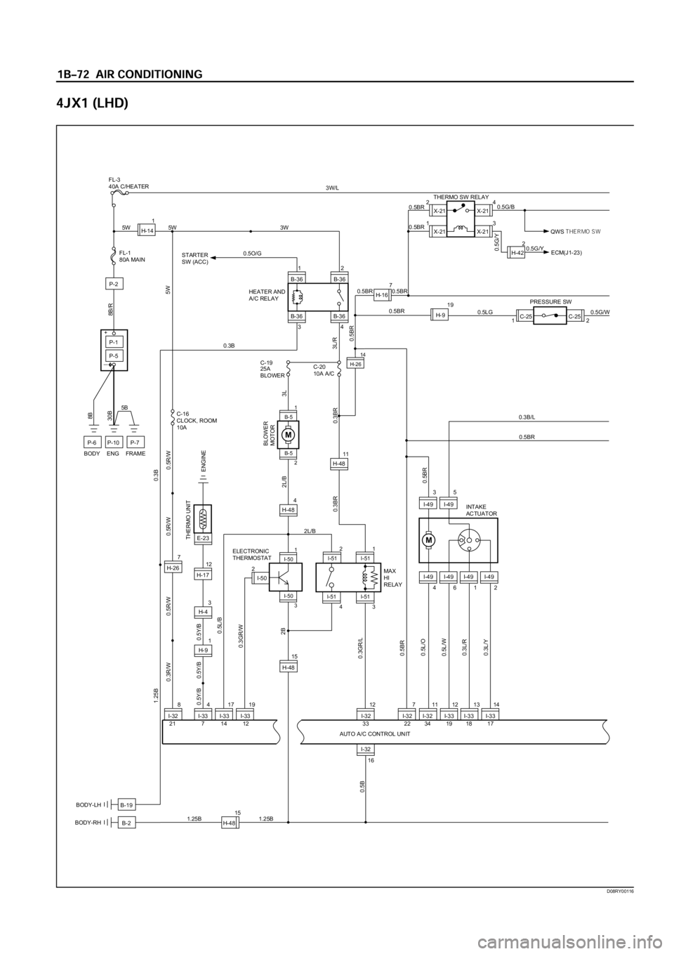
X-2124
13X-21
X-21 THERMO SW RELAY
0.5BR 0.5BR
0.5G/Y
QWS THE R MO S W 0.5G/BX-21
B-2BODY-RH
B-19 BODY-LH
I-32 I-33I-32 I-32 I-33 I-33
847111213
12
B-36 B-36
B-36 B-3634
7
H-26
5W 3W
5W
3L/R
C-16
CLOCK, ROOM
10AC-19
25A
BLOWERC-20
10A A/C
0.5Y/B 0.5Y/B 0.5Y/B0.5R/W 0.3R/W0.5R/W 0.5R/W
0.5BR
0.5BR0.5L/B
0.3GR/W
2B
0.3GR/L
0.5BR
HEATER AND
A/C RELAY STARTER
SW (ACC)
P-1
P-5
P-2
P-7P-10P-6
5B
2L/B30B8B
8B/R
FL-1
80A MAIN
+
�ー
I-32
H-481.25B
0.5B
151.25B
I-33
7 21 14 12 2233 34 19 18 1714
I-49
4612
M
I-49 I-49 I-49
I-493
5
I-49
16
0.5L/O
0.5L/W
0.3L/R
0.3L/Y
0.3B/L
1.25B0.3B
0.5BR
C-25
I-3317I-3319
H-9
3L 2L/B
0.3BR 0.3BR
0.5BR
0.5BR
C-25
2 1 19
0.5G/W 0.5LGPRESSURE SW
INTAKE
ACTUATOR
MAX
HI
RELAY ELECTRONIC
THERMOSTAT
THERMO UNIT
H-141
I-502 0.5O/G
5W
0.3B
BODY ENG FRAME
H-167
3
H-4
E-23
1
H-9
ENGINE
0.5BR
3W/LFL-3
40A C/HEATER
2H-420.5G/Y
ECM(J1-23)
12
H-17
B-51
H-2614
I-501
B-5
2
I-50
3
15
H-48
4
H-48
MBLOWER
MOTOR
I-51
2
I-511
43I-51
I-51
AUTO A/C CONTROL UNIT
I-3212
11
H-48
D08RY00116
Page 3704 of 6000
FULL AUTO display
INTAKE indication
(LED)
(switching between
fresh and interior air)
MODE indication
(LED) (Blow port)
AC display (LED)
FAN indication (LED)
FAN KNOB
AUTO SET
REC FRESH SWITCH
TEMP LEVER
(temperature control)
MODE SWITCH
(blow port selection)
AC SWITCH
IN CAR SENSOR
AMBIENT SENSOR
SUN SENSOR
DUCT SENSOR
MIX ACTUATOR
POTENTIOMETER
MODE ACTUATOR
POTENTIOMETER
AIR MIX DOOR
MODE DOOR
INTAKE ACTUATOR
RECINTAKE DOOR
FAN MOTORPOWER
TRANSISTOR
AUTOMATIC HEATER/AIR CONDITIONER CONTROL UNIT (with the built-in micro-computer)
MAX HI RELAY
PRESSURE
SWITCHAIR CONDITIONER
THERMO RELAY
COMPRESSOR
SWITCH MAGNET
CLUTCH
PCM
PRESSURE
SWITCHAIR CONDITIONER
THERMO RELAYMAGNET
CLUTCH
(4JX1engine)
MIX FRESH
F01RY00009