1998 OPEL FRONTERA engine
[x] Cancel search: enginePage 3214 of 6000
8F–19 BODY STRUCTURE
Engine Hood Lock
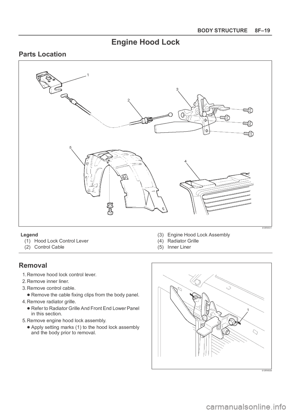
Parts Location
610RW011
Legend
(1) Hood Lock Control Lever
(2) Control Cable(3) Engine Hood Lock Assembly
(4) Radiator Grille
(5) Inner Liner
Removal
1. Remove hood lock control lever.
2. Remove inner liner.
3. Remove control cable.
Remove the cable fixing clips from the body panel.
4. Remove radiator grille.
Refer to Radiator Grille And Front End Lower Panel
in this section.
5. Remove engine hood lock assembly.
Apply setting marks (1) to the hood lock assembly
and the body prior to removal.
610RW009
Page 3245 of 6000
8F–50BODY STRUCTURE
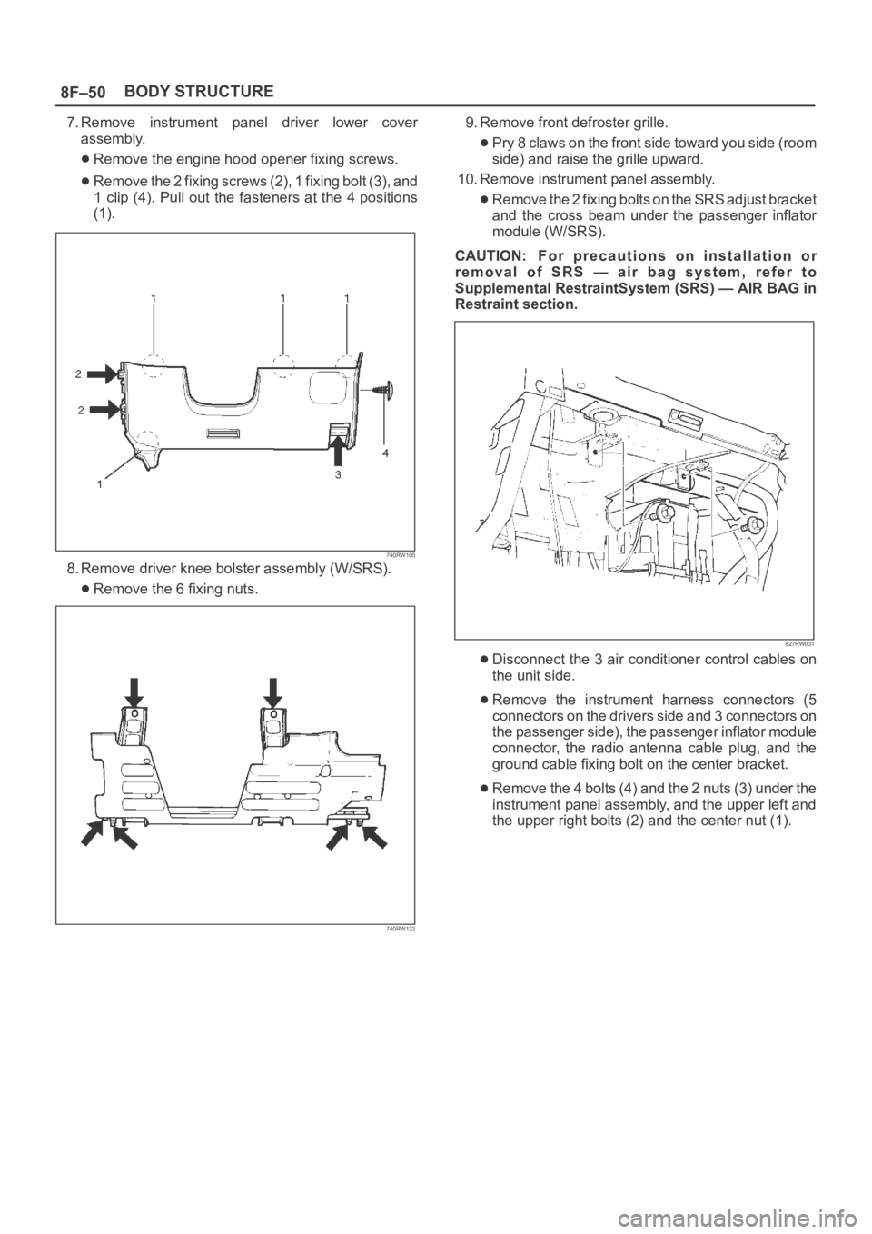
7. Remove instrument panel driver lower cover
assembly.
Remove the engine hood opener fixing screws.
Remove the 2 fixing screws (2), 1 fixing bolt (3), and
1 clip (4). Pull out the fasteners at the 4 positions
(1).
740RW105
8. Remove driver knee bolster assembly (W/SRS).
Remove the 6 fixing nuts.
740RW122
9. Remove front defroster grille.
Pry 8 claws on the front side toward you side (room
side) and raise the grille upward.
10. Remove instrument panel assembly.
Remove the 2 fixing bolts on the SRS adjust bracket
and the cross beam under the passenger inflator
module (W/SRS).
CAUTION: For precautions on installation or
removal of SRS — air bag system, refer to
Supplemental RestraintSystem (SRS) — AIR BAG in
Restraint section.
827RW031
Disconnect the 3 air conditioner control cables on
the unit side.
Remove the instrument harness connectors (5
connectors on the drivers side and 3 connectors on
the passenger side), the passenger inflator module
connector, the radio antenna cable plug, and the
ground cable fixing bolt on the center bracket.
Remove the 4 bolts (4) and the 2 nuts (3) under the
instrument panel assembly, and the upper left and
the upper right bolts (2) and the center nut (1).
Page 3248 of 6000
8F–53 BODY STRUCTURE
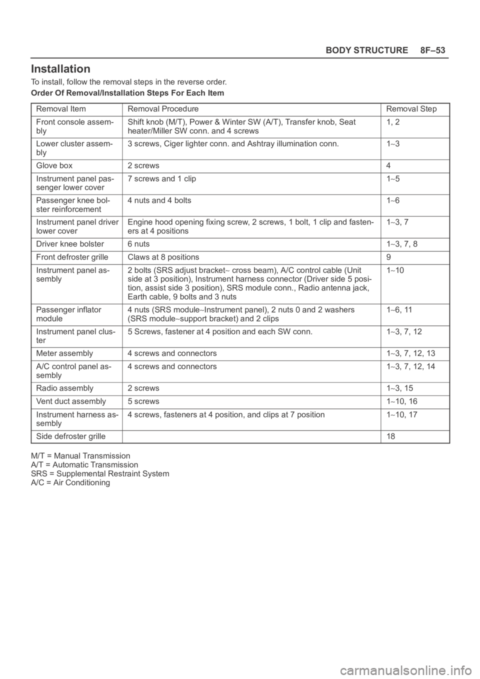
Installation
To install, follow the removal steps in the reverse order.
Order Of Removal/Installation Steps For Each Item
Removal Item
Removal ProcedureRemoval Step
Front console assem-
blyShift knob (M/T), Power & Winter SW (A/T), Transfer knob, Seat
heater/Miller SW conn. and 4 screws1, 2
Lower cluster assem-
bly3 screws, Ciger lighter conn. and Ashtray illumination conn.13
Glove box2 screws4
Instrument panel pas-
senger lower cover7 screws and 1 clip15
Passenger knee bol-
ster reinforcement4 nuts and 4 bolts16
Instrument panel driver
lower coverEngine hood opening fixing screw, 2 screws, 1 bolt, 1 clip and fasten-
ers at 4 positions13, 7
Driver knee bolster6 nuts13, 7, 8
Front defroster grilleClaws at 8 positions9
Instrument panel as-
sembly2 bolts (SRS adjust bracket cross beam), A/C control cable (Unit
side at 3 position), Instrument harness connector (Driver side 5 posi-
tion, assist side 3 position), SRS module conn., Radio antenna jack,
Earth cable, 9 bolts and 3 nuts110
Passenger inflator
module4 nuts (SRS moduleInstrument panel), 2 nuts 0 and 2 washers
(SRS module
support bracket) and 2 clips
16, 11
Instrument panel clus-
ter5 Screws, fastener at 4 position and each SW conn.13, 7, 12
Meter assembly4 screws and connectors13, 7, 12, 13
A/C control panel as-
sembly4 screws and connectors13, 7, 12, 14
Radio assembly2 screws13, 15
Vent duct assembly5 screws110, 16
Instrument harness as-
sembly4 screws, fasteners at 4 position, and clips at 7 position110, 17
Side defroster grille18
M/T = Manual Transmission
A/T = Automatic Transmission
SRS = Supplemental Restraint System
A/C = Air Conditioning
Page 3340 of 6000
SECURITY AND LOCKS8H–1
BODY AND ACCESSORIES
SECURITY AND LOCKS
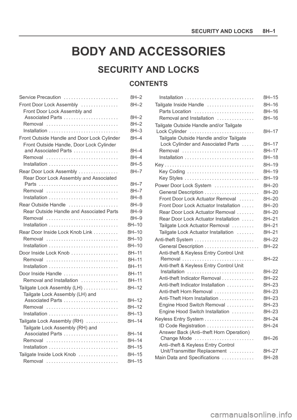
CONTENTS
Service Precaution 8H–2. . . . . . . . . . . . . . . . . . . . . .
Front Door Lock Assembly 8H–2. . . . . . . . . . . . . . .
Front Door Lock Assembly and
Associated Parts 8H–2. . . . . . . . . . . . . . . . . . . . . .
Removal 8H–2. . . . . . . . . . . . . . . . . . . . . . . . . . . . .
Installation 8H–3. . . . . . . . . . . . . . . . . . . . . . . . . . . .
Front Outside Handle and Door Lock Cylinder 8H–4
Front Outside Handle, Door Lock Cylinder
and Associated Parts 8H–4. . . . . . . . . . . . . . . . . .
Removal 8H–4. . . . . . . . . . . . . . . . . . . . . . . . . . . . .
Installation 8H–5. . . . . . . . . . . . . . . . . . . . . . . . . . . .
Rear Door Lock Assembly 8H–7. . . . . . . . . . . . . . . .
Rear Door Lock Assembly and Associated
Parts 8H–7. . . . . . . . . . . . . . . . . . . . . . . . . . . . . . . .
Removal 8H–7. . . . . . . . . . . . . . . . . . . . . . . . . . . . .
Installation 8H–8. . . . . . . . . . . . . . . . . . . . . . . . . . . .
Rear Outside Handle 8H–9. . . . . . . . . . . . . . . . . . . .
Rear Outside Handle and Associated Parts 8H–9
Removal 8H–9. . . . . . . . . . . . . . . . . . . . . . . . . . . . .
Installation 8H–10. . . . . . . . . . . . . . . . . . . . . . . . . . . .
Rear Door Inside Lock Knob Link 8H–10. . . . . . . . . .
Removal 8H–10. . . . . . . . . . . . . . . . . . . . . . . . . . . . .
Installation 8H–10. . . . . . . . . . . . . . . . . . . . . . . . . . . .
Door Inside Lock Knob 8H–11. . . . . . . . . . . . . . . . . . .
Removal 8H–11. . . . . . . . . . . . . . . . . . . . . . . . . . . . .
Installation 8H–11. . . . . . . . . . . . . . . . . . . . . . . . . . . .
Door Inside Handle 8H–11. . . . . . . . . . . . . . . . . . . . . .
Removal and Installation 8H–11. . . . . . . . . . . . . . .
Tailgate Lock Assembly (LH) 8H–12. . . . . . . . . . . . . .
Tailgate Lock Assembly (LH) and
Associated Parts 8H–12. . . . . . . . . . . . . . . . . . . . . .
Removal 8H–12. . . . . . . . . . . . . . . . . . . . . . . . . . . . .
Installation 8H–13. . . . . . . . . . . . . . . . . . . . . . . . . . . .
Tailgate Lock Assembly (RH) 8H–14. . . . . . . . . . . . .
Tailgate Lock Assembly (RH) and
Associated Parts 8H–14. . . . . . . . . . . . . . . . . . . . . .
Removal 8H–14. . . . . . . . . . . . . . . . . . . . . . . . . . . . .
Installation 8H–15. . . . . . . . . . . . . . . . . . . . . . . . . . . .
Tailgate Inside Lock Knob 8H–15. . . . . . . . . . . . . . . .
Removal 8H–15. . . . . . . . . . . . . . . . . . . . . . . . . . . . . Installation 8H–15. . . . . . . . . . . . . . . . . . . . . . . . . . . .
Tailgate Inside Handle 8H–16. . . . . . . . . . . . . . . . . . .
Parts Location 8H–16. . . . . . . . . . . . . . . . . . . . . . . .
Removal and Installation 8H–16. . . . . . . . . . . . . . .
Tailgate Outside Handle and/or Tailgate
Lock Cylinder 8H–17. . . . . . . . . . . . . . . . . . . . . . . . . .
Tailgate Outside Handle and/or Tailgate
Lock Cylinder and Associated Parts 8H–17. . . . .
Removal 8H–17. . . . . . . . . . . . . . . . . . . . . . . . . . . . .
Installation 8H–18. . . . . . . . . . . . . . . . . . . . . . . . . . . .
Key 8H–19. . . . . . . . . . . . . . . . . . . . . . . . . . . . . . . . . . . .
Key Coding 8H–19. . . . . . . . . . . . . . . . . . . . . . . . . . .
Key Styles 8H–19. . . . . . . . . . . . . . . . . . . . . . . . . . . . . .
Power Door Lock System 8H–20. . . . . . . . . . . . . . . .
General Description 8H–20
. . . . . . . . . . . . . . . . . . . . . .
Front Door Lock Actuator Removal 8H–20. . . . . .
Front Door Lock Actuator Installation 8H–20. . . . .
Rear Door Lock Actuator Removal 8H–20. . . . . . .
Rear Door Lock Actuator Installation 8H–21. . . . .
Tailgate Lock Actuator Removal 8H–21. . . . . . . . .
Tailgate Lock Actuator Installation 8H–21. . . . . . .
Anti-theft System 8H–22. . . . . . . . . . . . . . . . . . . . . . . .
General Description 8H–22. . . . . . . . . . . . . . . . . . . . . .
Anti-theft & Keyless Entry Control Unit
Removal 8H–22. . . . . . . . . . . . . . . . . . . . . . . . . . . . .
Anti-theft & Keyless Entry Control Unit
Installation 8H–22. . . . . . . . . . . . . . . . . . . . . . . . . . .
Anti-theft Indicator Removal 8H–22. . . . . . . . . . . . .
Anti-theft Indicator Installation 8H–23. . . . . . . . . . .
Anti-theft Horn Removal 8H–23. . . . . . . . . . . . . . . .
Anti-Theft Horn Installation 8H–23. . . . . . . . . . . . . .
Engine Hood Switch Removal 8H–23. . . . . . . . . . .
Engine Hood Switch Installation 8H–23. . . . . . . . .
Keyless Entry System 8H–24. . . . . . . . . . . . . . . . . . . .
ID Code Registration 8H–24. . . . . . . . . . . . . . . . . . .
Answer Back (Anti–theft Horn Operation)
Change Mode 8H–26. . . . . . . . . . . . . . . . . . . . . . . .
Anti–theft & Keyless Entry Control
Unit/Transmitter Replacement 8H–27. . . . . . . . . .
Main Data and Specifications 8H–28. . . . . . . . . . . . .
Page 3361 of 6000
8H–22SECURITY AND LOCKS
Anti-theft System
General Description
The circuit consists of the starter switch, anti-theft &
keyless entry control unit, anti-theft horn, front door and
tailgate key switch (detect and tamper switch), door lock
(& power window) switch, door lock actuator for each
door, engine hood switch, clutch start switch (M/T),
ANTI-THEFT indicator light and mode switch (A/T).
The system operates as follows: After locking the starter
switch and removing the starter key (this sets the alarm),
if the door is unlocked in any way other than with the
proper key, the headlights start flashing, the horn sounds,
and the starter circuit is disabled. (However, the engine
hood and all the doors must be locked and closed.)
Once the system has been placed in the warning or alarm
condition, it can be released only when the starter switch
is shifted from “OFF” to “ACC” by the starter key, or when
the lock of the front door or the tailgate is released (to
activate the detect switch) by the starter key.
Anti-theft & Keyless Entry Control
Unit Removal
1. Disconnect the battery ground cable.
2. Remove the front console assembly.
Refer to the Instrument Panel Assembly in Body
Structure section.
3. Remove the lower cluster assembly.
Refer to the Instrument Panel Assembly in Body
Structure section.
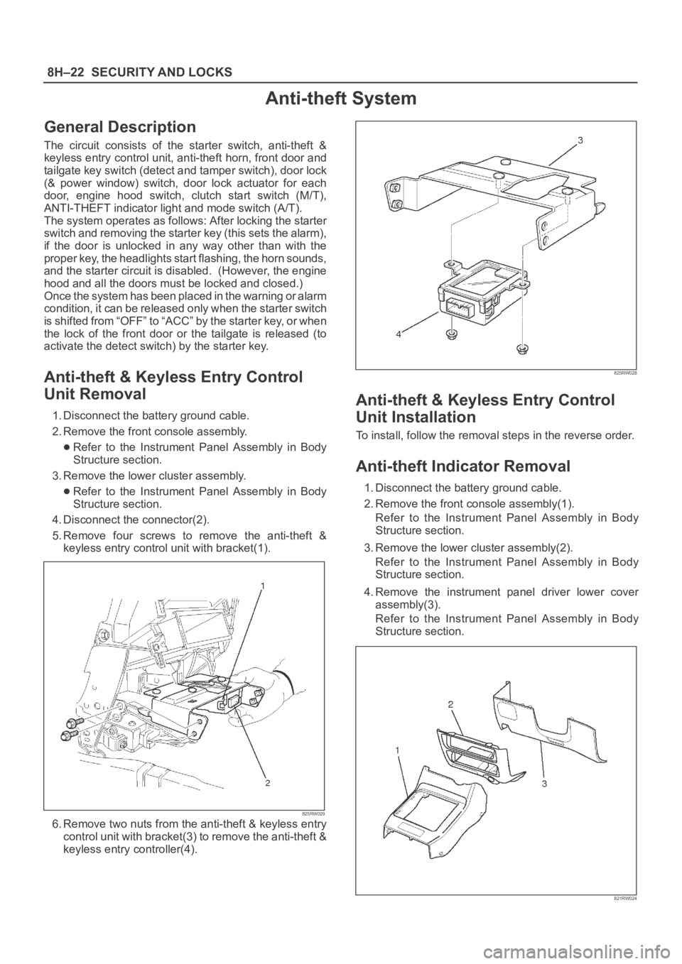
4. Disconnect the connector(2).
5. Remove four screws to remove the anti-theft &
keyless entry control unit with bracket(1).
825RW029
6. Remove two nuts from the anti-theft & keyless entry
control unit with bracket(3) to remove the anti-theft &
keyless entry controller(4).
825RW028
Anti-theft & Keyless Entry Control
Unit Installation
To install, follow the removal steps in the reverse order.
Anti-theft Indicator Removal
1. Disconnect the battery ground cable.
2. Remove the front console assembly(1).
Refer to the Instrument Panel Assembly in Body
Structure section.
3. Remove the lower cluster assembly(2).
Refer to the Instrument Panel Assembly in Body
Structure section.
4. Remove the instrument panel driver lower cover
assembly(3).
Refer to the Instrument Panel Assembly in Body
Structure section.
821RW024
Page 3362 of 6000
SECURITY AND LOCKS8H–23
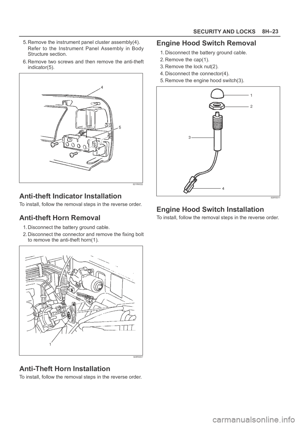
5. Remove the instrument panel cluster assembly(4).
Refer to the Instrument Panel Assembly in Body
Structure section.
6. Remove two screws and then remove the anti-theft
indicator(5).
821RW032
Anti-theft Indicator Installation
To install, follow the removal steps in the reverse order.
Anti-theft Horn Removal
1. Disconnect the battery ground cable.
2. Disconnect the connector and remove the fixing bolt
to remove the anti-theft horn(1).
828RS007
Anti-Theft Horn Installation
To install, follow the removal steps in the reverse order.
Engine Hood Switch Removal
1. Disconnect the battery ground cable.
2. Remove the cap(1).
3. Remove the lock nut(2).
4. Disconnect the connector(4).
5. Remove the engine hood switch(3).
828RS011
Engine Hood Switch Installation
To install, follow the removal steps in the reverse order.
Page 3441 of 6000
SUPPLEMENTAL RESTRAINT SYSTEM 9J–4
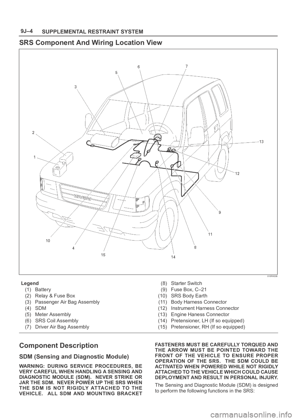
SRS Component And Wiring Location View
810RW298
Legend
(1) Battery
(2) Relay & Fuse Box
(3) Passenger Air Bag Assembly
(4) SDM
(5) Meter Assembly
(6) SRS Coil Assembly
(7) Driver Air Bag Assembly(8) Starter Switch
(9) Fuse Box, C–21
(10) SRS Body Earth
(11) Body Harness Connector
(12) Instrument Harness Connector
(13) Engine Haness Connector
(14) Pretensioner, LH (If so equipped)
(15) Pretensioner, RH (If so equipped)
Component Description
SDM (Sensing and Diagnostic Module)
WARNING: DURING SERVICE PROCEDURES, BE
VERY CAREFUL WHEN HANDLING A SENSING AND
DIAGNOSTIC MODULE (SDM). NEVER STRIKE OR
JAR THE SDM. NEVER POWER UP THE SRS WHEN
THE SDM IS NOT RIGIDLY ATTACHED TO THE
VEHICLE. ALL SDM AND MOUNTING BRACKETFASTENERS MUST BE CAREFULLY TORQUED AND
THE ARROW MUST BE POINTED TOWARD THE
FRONT OF THE VEHICLE TO ENSURE PROPER
OPERATION OF THE SRS. THE SDM COULD BE
ACTIVATED WHEN POWERED WHILE NOT RIGIDLY
ATTACHED TO THE VEHICLE WHICH COULD CAUSE
DEPLOYMENT AND RESULT IN PERSONAL INJURY.
The Sensing and Diagnostic Module (SDM) is designed
to perform the following functions in the SRS:
Page 3444 of 6000
SUPPLEMENTAL RESTRAINT SYSTEM9J–7
Steering Column
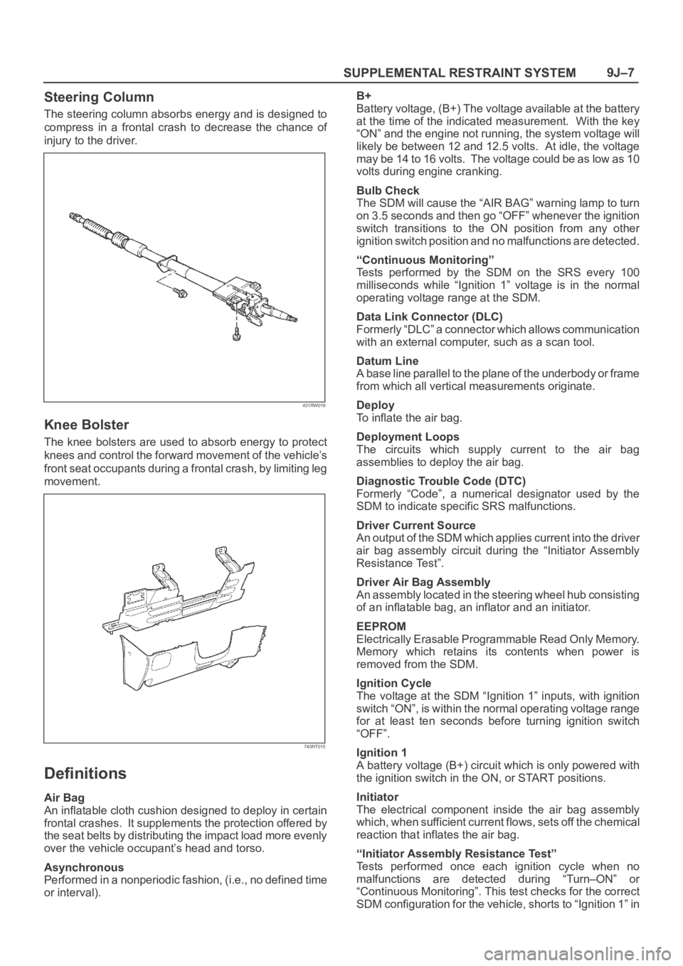
The steering column absorbs energy and is designed to
compress in a frontal crash to decrease the chance of
injury to the driver.
431RW019
Knee Bolster
The knee bolsters are used to absorb energy to protect
knees and control the forward movement of the vehicle’s
front seat occupants during a frontal crash, by limiting leg
movement.
740RT015
Definitions
Air Bag
An inflatable cloth cushion designed to deploy in certain
frontal crashes. It supplements the protection offered by
the seat belts by distributing the impact load more evenly
over the vehicle occupant’s head and torso.
Asynchronous
Performed in a nonperiodic fashion, (i.e., no defined time
or interval).B+
Battery voltage, (B+) The voltage available at the battery
at the time of the indicated measurement. With the key
“ON” and the engine not running, the system voltage will
likely be between 12 and 12.5 volts. At idle, the voltage
may be 14 to 16 volts. The voltage could be as low as 10
volts during engine cranking.
Bulb Check
The SDM will cause the “AIR BAG” warning lamp to turn
on 3.5 seconds and then go “OFF” whenever the ignition
switch transitions to the ON position from any other
ignition switch position and no malfunctions are detected.
“Continuous Monitoring”
Tests performed by the SDM on the SRS every 100
milliseconds while “Ignition 1” voltage is in the normal
operating voltage range at the SDM.
Data Link Connector (DLC)
Formerly “DLC” a connector which allows communication
with an external computer, such as a scan tool.
Datum Line
A base line parallel to the plane of the underbody or frame
from which all vertical measurements originate.
Deploy
To inflate the air bag.
Deployment Loops
The circuits which supply current to the air bag
assemblies to deploy the air bag.
Diagnostic Trouble Code (DTC)
Formerly “Code”, a numerical designator used by the
SDM to indicate specific SRS malfunctions.
Driver Current Source
An output of the SDM which applies current into the driver
air bag assembly circuit during the “Initiator Assembly
Resistance Test”.
Driver Air Bag Assembly
An assembly located in the steering wheel hub consisting
of an inflatable bag, an inflator and an initiator.
EEPROM
Electrically Erasable Programmable Read Only Memory.
Memory which retains its contents when power is
removed from the SDM.
Ignition Cycle
The voltage at the SDM “Ignition 1” inputs, with ignition
switch “ON”, is within the normal operating voltage range
for at least ten seconds before turning ignition switch
“OFF”.
Ignition 1
A battery voltage (B+) circuit which is only powered with
the ignition switch in the ON, or START positions.
Initiator
The electrical component inside the air bag assembly
which, when sufficient current flows, sets off the chemical
reaction that inflates the air bag.
“Initiator Assembly Resistance Test”
Tests performed once each ignition cycle when no
malfunctions are detected during “Turn–ON” or
“Continuous Monitoring”. This test checks for the correct
SDM configuration for the vehicle, shorts to “Ignition 1” in