Page 4126 of 6000
4B2–43 DRIVE LINE CONTROL SYSTEM (TOD)
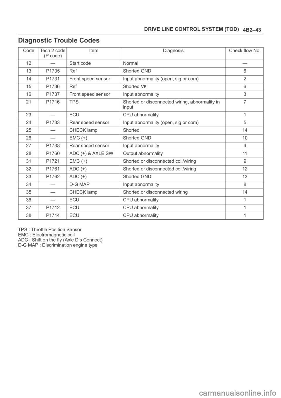
Diagnostic Trouble Codes
CodeTe c h 2 c o d e
(P code)ItemDiagnosisCheck flow No.
12—Start codeNormal—
13P1735RefShorted GND6
14P1731Front speed sensorInput abnormality (open, sig or com)2
15P1736RefShorted VB6
16P1737Front speed sensorInput abnormality3
21P1716TPSShorted or disconnected wiring, abnormality in
input7
23—ECUCPU abnormality1
24P1733Rear speed sensorInput abnormality (open, sig or com)5
25—CHECK lampShorted14
26—EMC (+)Shorted GND10
27P1738Rear speed sensorInput abnormality4
28P1760ADC (+) & AXLE SWOutput abnormality11
31P1721EMC (+)Shorted or disconnected coil/wiring9
32P1761ADC (+)Shorted or disconnected coil/wiring12
33P1762ADC (+)Shorted GND13
34—D-G MAPInput abnormality8
35—CHECK lampShorted or disconnected wiring14
36—ECUCPU abnormality1
37P1712ECUCPU abnormality1
38P1714ECUCPU abnormality1
TPS : Throttle Position Sensor
EMC : Electromagnetic coil
ADC : Shift on the fly (Axle Dis Connect)
D-G MAP : Discrimination engine type
Page 4129 of 6000
DRIVE LINE CONTROL SYSTEM (TOD) 4B2–46
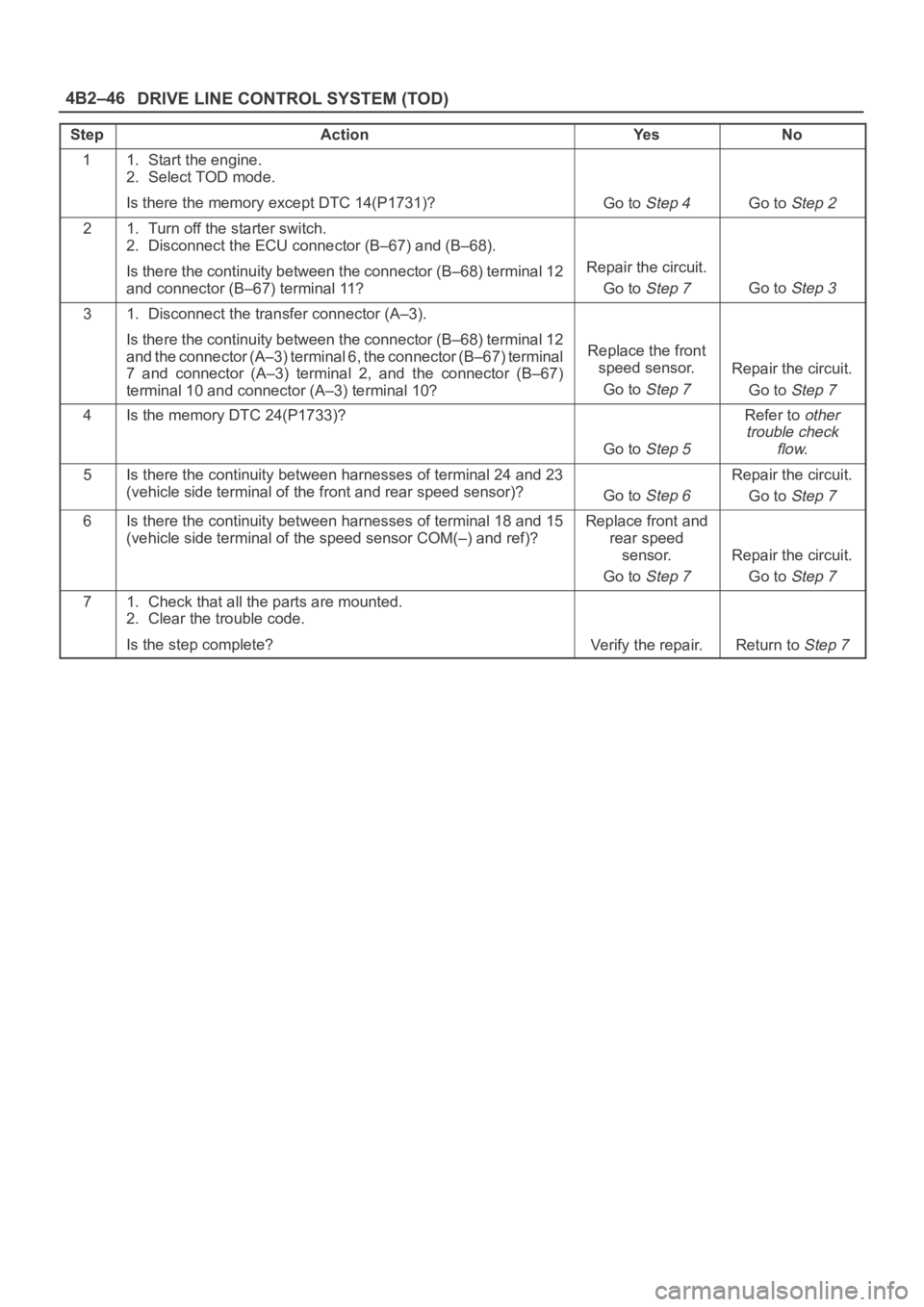
StepActionYe sNo
11. Start the engine.
2. Select TOD mode.
Is there the memory except DTC 14(P1731)?
Go to Step 4Go to Step 2
21. Turn off the starter switch.
2. Disconnect the ECU connector (B–67) and (B–68).
Is there the continuity between the connector (B–68) terminal 12
and connector (B–67) terminal 11?
Repair the circuit.
Go to
Step 7Go to Step 3
31. Disconnect the transfer connector (A–3).
Is there the continuity between the connector (B–68) terminal 12
and the connector (A–3) terminal 6, the connector (B–67) terminal
7 and connector (A–3) terminal 2, and the connector (B–67)
terminal 10 and connector (A–3) terminal 10?
Replace the front
speed sensor.
Go to
Step 7
Repair the circuit.
Go to
Step 7
4Is the memory DTC 24(P1733)?
Go to Step 5
Refer to other
trouble check
flow.
5Is there the continuity between harnesses of terminal 24 and 23
(vehicle side terminal of the front and rear speed sensor)?
Go to Step 6
Repair the circuit.
Go to
Step 7
6Is there the continuity between harnesses of terminal 18 and 15
(vehicle side terminal of the speed sensor COM(–) and ref)?Replace front and
rear speed
sensor.
Go to
Step 7
Repair the circuit.
Go to
Step 7
71. Check that all the parts are mounted.
2. Clear the trouble code.
Is the step complete?
Verify the repair.Return to Step 7
Page 4135 of 6000
DRIVE LINE CONTROL SYSTEM (TOD) 4B2–52
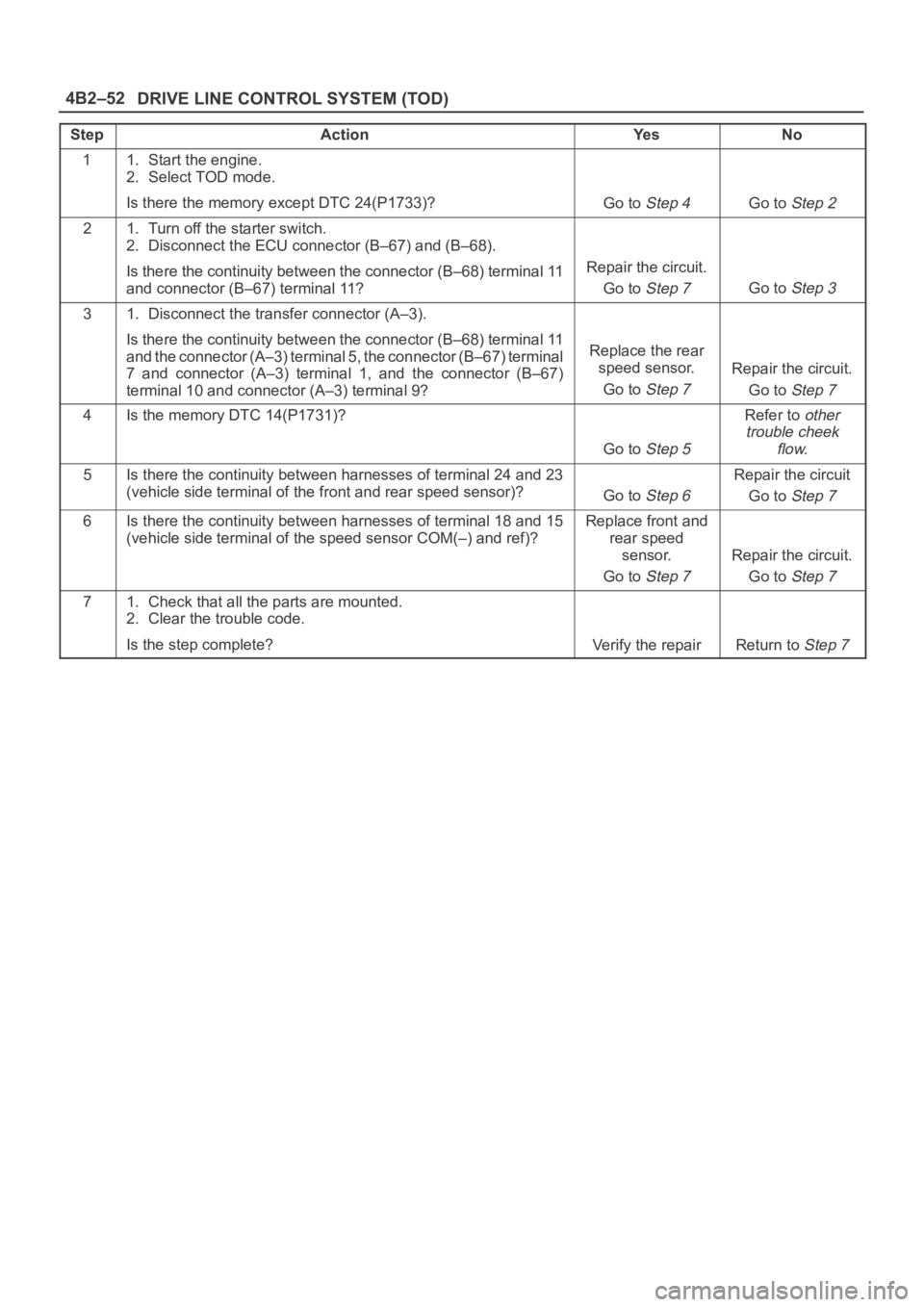
StepActionYe sNo
11. Start the engine.
2. Select TOD mode.
Is there the memory except DTC 24(P1733)?
Go to Step 4Go to Step 2
21. Turn off the starter switch.
2. Disconnect the ECU connector (B–67) and (B–68).
Is there the continuity between the connector (B–68) terminal 11
and connector (B–67) terminal 11?
Repair the circuit.
Go to
Step 7Go to Step 3
31. Disconnect the transfer connector (A–3).
Is there the continuity between the connector (B–68) terminal 11
and the connector (A–3) terminal 5, the connector (B–67) terminal
7 and connector (A–3) terminal 1, and the connector (B–67)
terminal 10 and connector (A–3) terminal 9?
Replace the rear
speed sensor.
Go to
Step 7
Repair the circuit.
Go to
Step 7
4Is the memory DTC 14(P1731)?
Go to Step 5
Refer to other
trouble cheek
flow.
5Is there the continuity between harnesses of terminal 24 and 23
(vehicle side terminal of the front and rear speed sensor)?
Go to Step 6
Repair the circuit
Go to
Step 7
6Is there the continuity between harnesses of terminal 18 and 15
(vehicle side terminal of the speed sensor COM(–) and ref)?Replace front and
rear speed
sensor.
Go to
Step 7
Repair the circuit.
Go to
Step 7
71. Check that all the parts are mounted.
2. Clear the trouble code.
Is the step complete?
Verify the repairReturn to Step 7
Page 4137 of 6000
DRIVE LINE CONTROL SYSTEM (TOD) 4B2–54
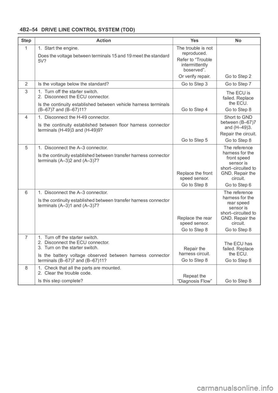
StepActionYe sNo
11. Start the engine.
Does the voltage between terminals 15 and 19 meet the standard
5V?The trouble is not
reproduced.
Refer to “Trouble
intermittently
boserved”.
Or verify repair.
Go to Step 2
2Is the voltage below the standard?Go to Step 3Go to Step 7
31. Turn off the starter switch.
2. Disconnect the ECU connector.
Is the continuity established between vehicle harness terminals
(B–67)7 and (B–67)11?
Go to Step 4
The ECU is
failed. Replace
the ECU.
Go to Step 8
41. Disconnect the H-49 connector.
Is the continuity established between floor harness connector
terminals (H-49)3 and (H-49)9?
Go to Step 5
Short to GND
between (B–67)7
and (H–49)3.
Repair the circuit.
Go to Step 8
51. Disconnect the A–3 connector.
Is the continuity established between transfer harness connector
terminals (A–3)2 and (A–3)7?
Replace the front
speed sensor.
Go to Step 8
The reference
harness for the
front speed
sensor is
short–circuited to
GND. Repair the
circuit.
Go to Step 6
61. Disconnect the A–3 connector.
Is the continuity established between transfer harness connector
terminals (A–3)1 and (A–3)7?
Replace the rear
speed sensor.
Go to Step 8
The reference
harness for the
rear speed
sensor is
short–circuited to
GND. Repair the
circuit.
Go to Step 8
71. Turn off the starter switch.
2. Disconnect the ECU connector.
3. Turn on the starter switch.
Is the battery voltage observed between harness connector
terminals (B–67)7 and (B–67)11?
Repair the
harness circuit.
Go to Step 8
The ECU has
failed. Replace
the ECU.
Go to Step 8
81. Check that all the parts are mounted.
2. Clear the trouble code.
Is this step complete?
Repeat the
“Diagnosis Flow”
Go to Step 8
Page 4140 of 6000
4B2–57 DRIVE LINE CONTROL SYSTEM (TOD)
Check flowTrouble codePhenomenonStandard
834The diesel/gasoline engine identifi-
cation signal is faulty.6VE1: Continuity established
4JX1: No continuity
The engine identification signals of 6VE1 and 4JX1 are
changed each other.
D04RY00053
Page 4143 of 6000
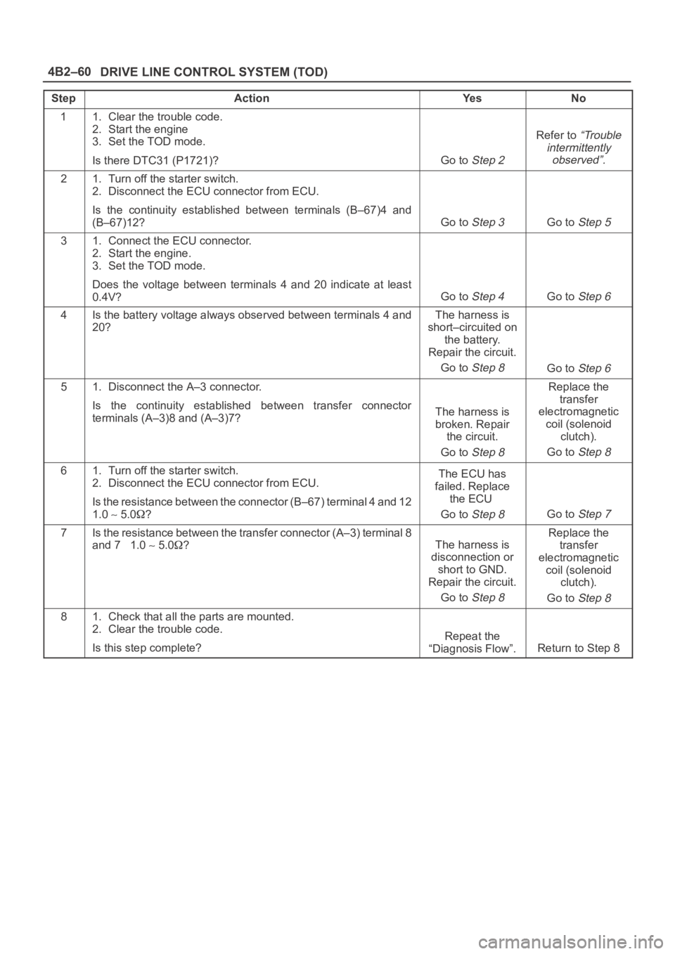
DRIVE LINE CONTROL SYSTEM (TOD) 4B2–60
StepActionYe sNo
11. Clear the trouble code.
2. Start the engine
3. Set the TOD mode.
Is there DTC31 (P1721)?
Go to Step 2
Refer to “Trouble
intermittently
observed”.
21. Turn off the starter switch.
2. Disconnect the ECU connector from ECU.
Is the continuity established between terminals (B–67)4 and
(B–67)12?
Go to Step 3Go to Step 5
31. Connect the ECU connector.
2. Start the engine.
3. Set the TOD mode.
Does the voltage between terminals 4 and 20 indicate at least
0.4V?
Go to Step 4Go to Step 6
4Is the battery voltage always observed between terminals 4 and
20?The harness is
short–circuited on
the battery.
Repair the circuit.
Go to
Step 8Go to Step 6
51. Disconnect the A–3 connector.
Is the continuity established between transfer connector
terminals (A–3)8 and (A–3)7?
The harness is
broken. Repair
the circuit.
Go to
Step 8
Replace the
transfer
electromagnetic
coil (solenoid
clutch).
Go to
Step 8
61. Turn off the starter switch.
2. Disconnect the ECU connector from ECU.
Is the resistance between the connector (B–67) terminal 4 and 12
1.0
5.0?
The ECU has
failed. Replace
the ECU
Go to
Step 8Go to Step 7
7Is the resistance between the transfer connector (A–3) terminal 8
and 7 1.0
5.0?The harness is
disconnection or
short to GND.
Repair the circuit.
Go to
Step 8
Replace the
transfer
electromagnetic
coil (solenoid
clutch).
Go to
Step 8
81. Check that all the parts are mounted.
2. Clear the trouble code.
Is this step complete?
Repeat the
“Diagnosis Flow”.
Return to Step 8
Page 4145 of 6000
DRIVE LINE CONTROL SYSTEM (TOD) 4B2–62
StepActionYe sNo
11. Turn off the starter switch.
2. Disconnect the ECU connector from ECU.
Does the resistance between terminals (B–67)4 and (B–67)12?
indicate 1.0 to 5.0 ohm?
Go to Step 2Go to Step 3
21. Connect the ECU connector.
2. Start the engine.
3. Set the TOD mode.
When the throttle is operated between full close and full open
positions, does the voltage between terminals 4 and 20 indicate
0.1 to 1.0 V?The phenomenon
is not
reproduced.
Refer to
“Troubles
intermittently
observed”.
The ECU has
failed. Replace
the ECU.
Go to Step 4
3Does the resistance between transfer connector terminals (A–3)8
and (A–3)7 indicate 1.0 to 5.0ohm?
The harness is
broken. Repair
the circuit.
Go to Step 4
Replace the
transfer
electromagnetic
coil.
Go to Step 4
41. Check that all the parts are mounted.
2. Clear the trouble code.
Is this step complete?
Repeat the
“Diagnosis Flow”.
Return to Step 4
Page 4185 of 6000
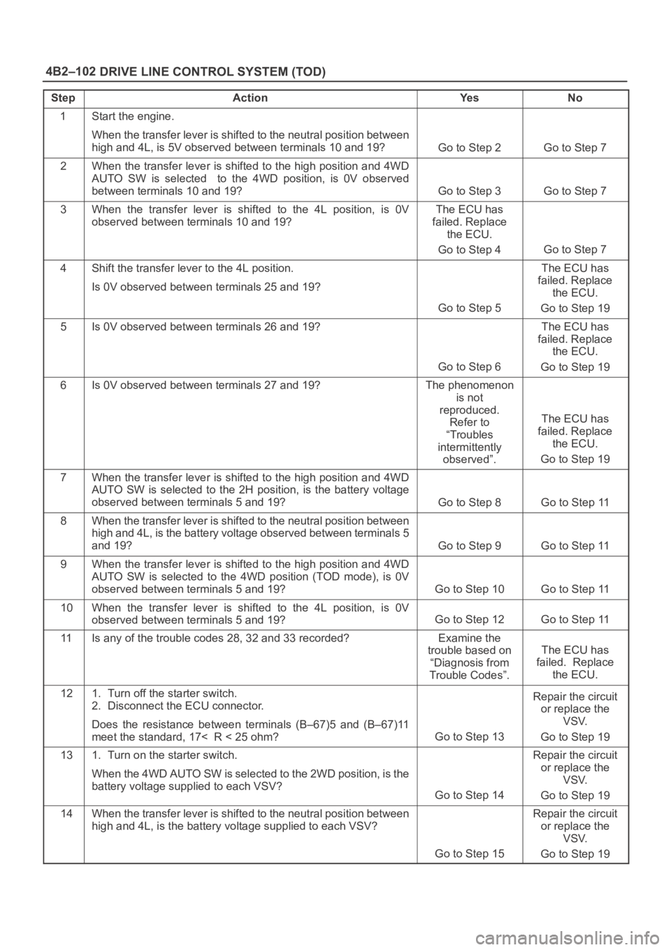
DRIVE LINE CONTROL SYSTEM (TOD) 4B2–102
StepActionYe sNo
1Start the engine.
When the transfer lever is shifted to the neutral position between
high and 4L, is 5V observed between terminals 10 and 19?
Go to Step 2Go to Step 7
2When the transfer lever is shifted to the high position and 4WD
AUTO SW is selected to the 4WD position, is 0V observed
between terminals 10 and 19?
Go to Step 3Go to Step 7
3When the transfer lever is shifted to the 4L position, is 0V
observed between terminals 10 and 19?The ECU has
failed. Replace
the ECU.
Go to Step 4
Go to Step 7
4Shift the transfer lever to the 4L position.
Is 0V observed between terminals 25 and 19?
Go to Step 5
The ECU has
failed. Replace
the ECU.
Go to Step 19
5Is 0V observed between terminals 26 and 19?
Go to Step 6
The ECU has
failed. Replace
the ECU.
Go to Step 19
6Is 0V observed between terminals 27 and 19?The phenomenon
is not
reproduced.
Refer to
“Troubles
intermittently
observed”.
The ECU has
failed. Replace
the ECU.
Go to Step 19
7When the transfer lever is shifted to the high position and 4WD
AUTO SW is selected to the 2H position, is the battery voltage
observed between terminals 5 and 19?
Go to Step 8Go to Step 11
8When the transfer lever is shifted to the neutral position between
high and 4L, is the battery voltage observed between terminals 5
and 19?
Go to Step 9Go to Step 11
9When the transfer lever is shifted to the high position and 4WD
AUTO SW is selected to the 4WD position (TOD mode), is 0V
observed between terminals 5 and 19?
Go to Step 10Go to Step 11
10When the transfer lever is shifted to the 4L position, is 0V
observed between terminals 5 and 19?
Go to Step 12Go to Step 11
11Is any of the trouble codes 28, 32 and 33 recorded?Examine the
trouble based on
“Diagnosis from
Trouble Codes”.
The ECU has
failed. Replace
the ECU.
121. Turn off the starter switch.
2. Disconnect the ECU connector.
Does the resistance between terminals (B–67)5 and (B–67)11
meet the standard, 17< R < 25 ohm?
Go to Step 13
Repair the circuit
or replace the
VSV.
Go to Step 19
131. Turn on the starter switch.
When the 4WD AUTO SW is selected to the 2WD position, is the
battery voltage supplied to each VSV?
Go to Step 14
Repair the circuit
or replace the
VSV.
Go to Step 19
14When the transfer lever is shifted to the neutral position between
high and 4L, is the battery voltage supplied to each VSV?
Go to Step 15
Repair the circuit
or replace the
VSV.
Go to Step 19