1998 OPEL FRONTERA radiator
[x] Cancel search: radiatorPage 5372 of 6000
ENGINE COOLING 6B – 3
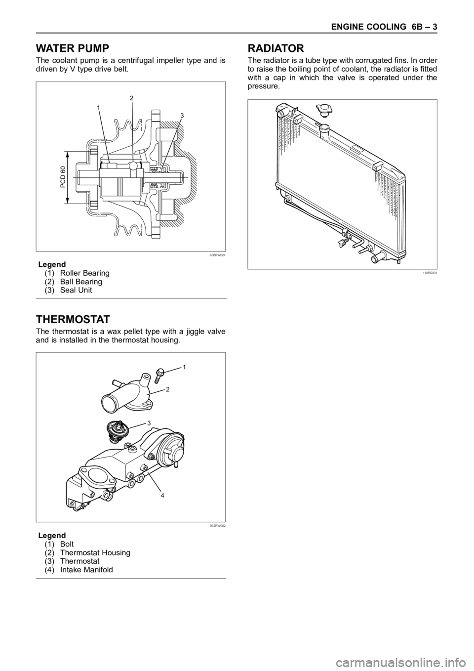
WAT E R P U M P
The coolant pump is a centrifugal impeller type and is
driven by V type drive belt.
Legend
(1) Roller Bearing
(2) Ball Bearing
(3) Seal Unit
THERMOSTAT
The thermostat is a wax pellet type with a jiggle valve
and is installed in the thermostat housing.
Legend
(1) Bolt
(2) Thermostat Housing
(3) Thermostat
(4) Intake Manifold
RADIATOR
The radiator is a tube type with corrugated fins. In order
to raise the boiling point of coolant, the radiator is fitted
with a cap in which the valve is operated under the
pressure.
1
3 2
PCD 60
A06RW024
1
2
3
4
032RW002
110RS001
Page 5374 of 6000

ENGINE COOLING 6B – 5
ENGINE COOLANT CHANGE
PROCEDURE
1. To change engine coolant, make sure that the
engine is cool.
WARNING:
When the coolant is heated to a high temperature,
be sure not to loosen or remove the radiator cap.
Otherwise you might get scalded by hot vapor or
boiling water. To open the radiator cap, put a piece
of thick cloth on the cap and loosen the cap slowly
to reduce the pressure once the coolant has
become cooler.
2. Open radiator cap and drain the cooling system by
loosening the drain valve on the radiator and on the
cylinder body.
NOTE: For best results it is suggested that the engine
cooling system be flushed at least once a year. It is
advisable to flush the interior of the cooling system
including the radiator before using anti-freeze
(ethylene-glycol based).
Replace damaged rubber hoses as the engine anti-
freeze coolant is liable to leak out even minor cracks.
Isuzu recommends using Isuzu genuine anti-freeze
(ethylene-glycol based) or equivalent, for the cooling
system and not add any inhibitors or additives.
CAUTION:
A failure to correctly fill the engine cooling system
in changing or topping off coolant may sometimes
cause the coolant to overflow from the filler neck
even before the engine and radiator are completely
full.
If the engine runs under this condition, shortage of
coolant may possibly result in engine overheating.
To avoid such trouble, the following precautions
should be taken in filling the system.
3. To refill engine coolant, pour coolant up to filler neck
using a filling hose which is smaller in outside
diameter than the filler neck. Otherwise air between
the filler neck and the filling hose will block entry,
preventing the system from completely filling up.
4. Keep a filling rate of 9 liter/min. or less. Filling over
this maximum rate may force air inside the engine
and radiator.
And also, the coolant overflow will increase, making
it difficult to determine whether or not the system is
completely full.
5. After filling the system full, pull out the filling hose
and check to see if air trapped in the system is
dislodged and the coolant level goes down. Should
the coolant level go down, repeat topping-off until
there is no more drop in the coolant level.
6. Directly after filling the radiator, fill the reservoir to
the maximum level.
7. Install and tighten radiator cap and start the engine.
After idling for 2 to 3 minutes, stop the engine and
reopen radiator cap. If the water level is lower,
replenish.WARNING:
When the coolant is heated to a high temperature,
be sure not to loosen or remove the radiator cap.
Otherwise you might get scalded by hot vapor or
boiling water. To open the radiator cap, put a piece
of thick cloth on the cap and loosen the cap slowly
to reduce the pressure once the coolant has
become cooler.
8. After tightening radiator cap, warm up the engine at
about 2,000 rpm.
Set heater adjustment to the highest temperature
position, and let the coolant circulate also into
heater water system.
9. Check to see the thermostat has opened by the
needle position of a water thermometer, conduct a
5-minute idle again and stop the engine.
10. When the engine has been cooled, check filler neck
for water level and replenish if required. Should
extreme shortage of coolant be found, check the
coolant system and reservoir tank hose for leakage.
11. Fill the coolant into the reservoir tank up to “MAX”
line.
Page 5376 of 6000

ENGINE COOLING 6B – 7
THERMOSTAT
REMOVAL
1. Disconnect battery ground cable.
2. Drain coolant from the radiator and engine.
3. Thermostat housing
1) Remove mounting bolt and remove thermostat
housing together with radiator hose.
4. Gasket
5. Thermostat
INSPECTION
Make necessary repair and parts replacement if
excessive wear or damage is found during inspection.
Submerge the thermostat assembly in the water.
Place wooden blocks on the bottom of the water
container.
Do not heat the thermostat directly.
Gradually increase the water temperature. Stir the
water so that the entire water is the same temperature.
1) Make sure that valve begins to open at the
specified temperature.
Valve Opening Temperature: 85°C (185°F)
2) Make sure that valve opens fully at the specified
temperature.
Valve Full Open Temperature: 100°C (212°F)
1
2
3
4
Legend
(1) Bolt
(2) Thermostat Housing
(3) Thermostat
(4) Intake Manifold
035RW002
031RS003
Page 5378 of 6000
ENGINE COOLING 6B – 9
RADIATOR
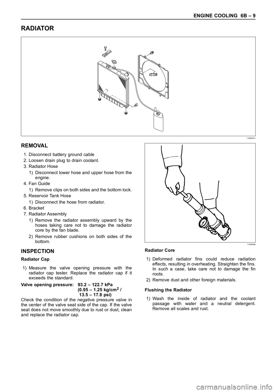
REMOVAL
1. Disconnect battery ground cable
2. Loosen drain plug to drain coolant.
3. Radiator Hose
1) Disconnect lower hose and upper hose from the
engine.
4. Fan Guide
1) Remove clips on both sides and the bottom lock.
5. Reservoir Tank Hose
1) Disconnect the hose from radiator.
6. Bracket
7. Radiator Assembly
1) Remove the radiator assembly upward by the
hoses taking care not to damage the radiator
core by the fan blade.
2) Remove rubber cushions on both sides of the
bottom.
INSPECTION
Radiator Cap
1) Measure the valve opening pressure with the
radiator cap tester. Replace the radiator cap if it
exceeds the standard.
Valve opening pressure: 93.2 – 122.7 kPa
(0.95 – 1.25 kg/cm
2/
13.5 – 17.8 psi)
Check the condition of the negative pressure valve in
the center of the valve seat side of the cap. If the valve
seat does not move smoothly due to rust or dust, clean
and replace the radiator cap.Radiator Core
1) Deformed radiator fins could reduce radiation
effects, resulting in overheating. Straighten the fins.
In such a case, take care not to damage the fin
roots.
2) Remove dust and other foreign materials.
Flushing the Radiator
1) Wash the inside of radiator and the coolant
passage with water and a neutral detergent.
Remove all scales and rust.
110RW017
110RS006
Page 5379 of 6000
6B – 10 ENGINE COOLING
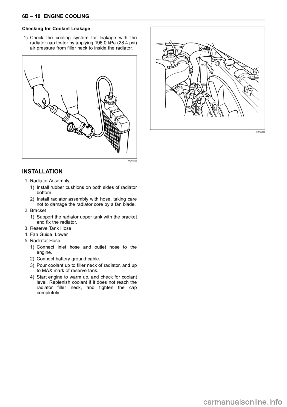
Checking for Coolant Leakage
1) Check the cooling system for leakage with the
radiator cap tester by applying 196.0 kPa (28.4 psi)
air pressure from filler neck to inside the radiator.
INSTALLATION
1. Radiator Assembly
1) Install rubber cushions on both sides of radiator
bottom.
2) Install radiator assembly with hose, taking care
not to damage the radiator core by a fan blade.
2. Bracket
1) Support the radiator upper tank with the bracket
and fix the radiator.
3. Reserve Tank Hose
4. Fan Guide, Lower
5. Radiator Hose
1) Connect inlet hose and outlet hose to the
engine.
2) Connect battery ground cable.
3) Pour coolant up to filler neck of radiator, and up
to MAX mark of reserve tank.
4) Start engine to warm up, and check for coolant
level. Replenish coolant if it does not reach the
radiator filler neck, and tighten the cap
completely.
110RS005
012RW080
Page 5470 of 6000
6E–41 4JX1–TC ENGINE DRIVEABILITY AND EMISSIONS
EGR (Exhaust Gas Recirculation)
Diagnosis
A diagnosis of the EGR system is covered by DTC
P1403.
EGR VSV circuit diagnosis is covered by DTC P1404.
EGR pressure sensor diagnosis is covered by DTC
P405 and/or P406.
EGR EVRV circuit diagnosis is covered by DTC
P1405. Refer to the DTC charts.
Tech 2 Data Definitions and Ranges
A/C CLUTCH–Tech 2 Displays ON or OFF–
Indicates whether the A/C has commanded the A/C
clutch ON.
MAP kPa — Tech 2 Range 10-105 kPa/0.00-5.00
Vo l t s —
The manifold absolute pressure reading is determined
from the MAP sensor signal monitored during key up and
wide open throttle (WOT) conditions. The manifold
absolute pressure is used to compensate for altitude
differences and is normally displayed around “61-104”
depending on altitude and manifold absolute pressure.
CMP ACT. COUNTER –Cam Position
DESIRED IDLE — Tech 2 Range 0-3187 RPM —
The idle speed that the ECM is commanding. The ECM
will compensate for various engine loads based on engine
coolant temperature, to keep the engine at the desired
speed.
ECT — (Engine Coolant Temperature) Tech 2
Range –40
C to 151C (–40F to 304F) —
The engine coolant temperature (ECT) is mounted in the
coolant stream and sends engine temperature
information to the ECM. The ECM applies 5 volts to the
ECT sensor circuit. The sensor is a thermistor which
changes internal resistance as temperature changes.
When the sensor is cold (high resistance), the ECM
monitors a high signal voltage and interprets that as a cold
engine. As the sensor warms (decreasing resistance),
the voltage signal will decrease and the ECM will interpret
the lower voltage as a warm engine.
ENGINE RUN TIME — Tech 2 Range
00:00:00-99:99:99 Hrs:Min:Sec —
Indicates the time elapsed since the engine was started.
If the engine is stopped, engine run time will be reset to
00:00:00.
ENGINE SPEED — Range 0-9999 RPM —
Engine speed is computed by the ECM from the 57X
reference input. It should remain close to desired idle
under various engine loads with engine idling.Air Intake Valve meter POSITION — Tech 2 Range
0-100 % —
IAT (INTAKE AIR TEMPERATURE)— Tech 2 Range
–40
C to 151C (–40F to 304F) —
The ECM converts the resistance of the intake air
temperature sensor to degrees. Intake air temperature
(IAT) is used by the ECM to adjust fuel delivery and spark
timing according to incoming air density.
MAP — Tech 2 Range 10-105 kPa (0.00-4.97 Volts)—
The manifold absolute pressure (MAP) sensor measures
the change in the boost pressure.
MIL — Tech 2 Displays ON or OFF —
Indicates the ECM commanded state of the malfunction
indicator lamp.
AP — Tech 2 Range 0%-100% —
AP (Accelerator position) angle is computed by the ECM
from the AP sensor voltage. AP angle should display
“0%” at idle and “100%” at wide open throttle.
AP SENSOR — Tech 2 Range 0.00-5.00 Volts —
The voltage being monitored by the ECM on the AP
sensor signal circuit.
VEHICLE SPEED—Tech 2 Range 0-255 km/h (0-155
mph)–
The vehicle speed sensor signal is converted into km/h
and mph for display.
Typical Scan Data Values
Use the Typical Scan Data Values Table only after the
On-Board Diagnostic System Check has been
completed, no DTC(s) were noted, and you have
determined that the on-board diagnostics are functioning
properly. Tech 2 values from a properly-running engine
may be used for comparison with the engine you are
diagnosing. The typical scan data values represent
values that would be seen on a normally-running engine.
NOTE: A Tech 2 that displays faulty data should not be
used, and the problem should be reported to the Tech 2
manufacturer. Use of a faulty Tech 2 can result in
misdiagnosis and unnecessary replacement of parts.
Only the parameters listed below are referred to in this
service manual for use in diagnosis. For further
information on using the Tech 2 to diagnose the ECM and
related sensors, refer to the applicable reference section
listed below. If all values are within the typical range
described below, refer to the
Symptoms section for
diagnosis.
Test Conditions
Engine running, lower radiator hose hot, transmission in
park or neutral, accessaries off, brake not applied and air
conditioning off.
Page 5537 of 6000
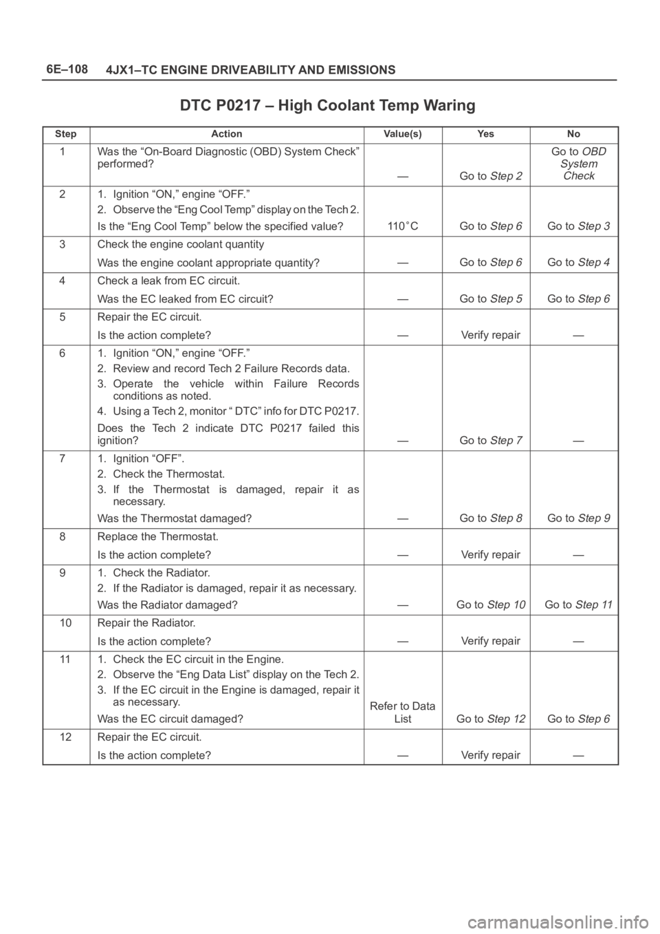
6E–108
4JX1–TC ENGINE DRIVEABILITY AND EMISSIONS
DTC P0217 – High Coolant Temp Waring
StepActionVa l u e ( s )Ye sNo
1Was the “On-Board Diagnostic (OBD) System Check”
performed?
—Go to Step 2
Go to OBD
System
Check
21. Ignition “ON,” engine “OFF.”
2. Observe the “Eng Cool Temp” display on the Tech 2.
Is the “Eng Cool Temp” below the specified value?
11 0CGo to Step 6Go to Step 3
3Check the engine coolant quantity
Was the engine coolant appropriate quantity?
—Go to Step 6Go to Step 4
4Check a leak from EC circuit.
Was the EC leaked from EC circuit?
—Go to Step 5Go to Step 6
5Repair the EC circuit.
Is the action complete?
—Verify repair—
61. Ignition “ON,” engine “OFF.”
2. Review and record Tech 2 Failure Records data.
3. Operate the vehicle within Failure Records
conditions as noted.
4. Using a Tech 2, monitor “ DTC” info for DTC P0217.
Does the Tech 2 indicate DTC P0217 failed this
ignition?
—Go to Step 7—
71. Ignition “OFF”.
2. Check the Thermostat.
3. If the Thermostat is damaged, repair it as
necessary.
Was the Thermostat damaged?
—Go to Step 8Go to Step 9
8Replace the Thermostat.
Is the action complete?
—Verify repair—
91. Check the Radiator.
2. If the Radiator is damaged, repair it as necessary.
Was the Radiator damaged?
—Go to Step 10Go to Step 11
10Repair the Radiator.
Is the action complete?
—Verify repair—
111. Check the EC circuit in the Engine.
2. Observe the “Eng Data List” display on the Tech 2.
3. If the EC circuit in the Engine is damaged, repair it
as necessary.
Was the EC circuit damaged?
Refer to Data
List
Go to Step 12Go to Step 6
12Repair the EC circuit.
Is the action complete?
—Verify repair—
Page 5632 of 6000
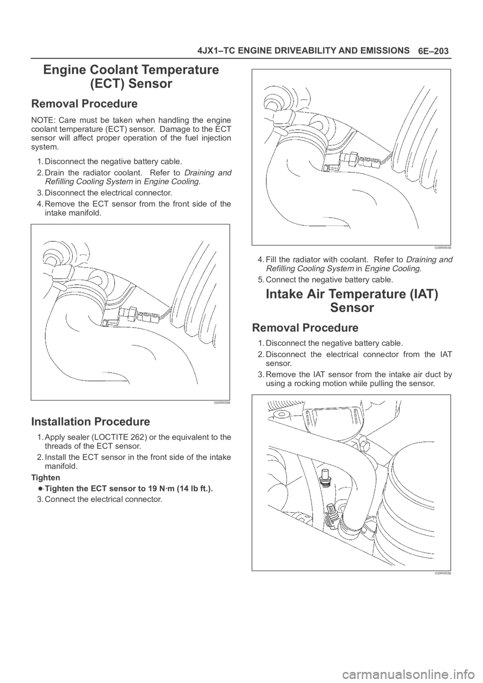
6E–203 4JX1–TC ENGINE DRIVEABILITY AND EMISSIONS
Engine Coolant Temperature
(ECT) Sensor
Removal Procedure
NOTE: Care must be taken when handling the engine
coolant temperature (ECT) sensor. Damage to the ECT
sensor will affect proper operation of the fuel injection
system.
1. Disconnect the negative battery cable.
2. Drain the radiator coolant. Refer to
Draining and
Refilling Cooling System
in Engine Cooling.
3. Disconnect the electrical connector.
4.Remove the ECT sensor from the front side of the
intake manifold.
035RW058
Installation Procedure
1. Apply sealer (LOCTITE 262) or the equivalent to the
threads of the ECT sensor.
2. Install the ECT sensor in the front side of the intake
manifold.
Tighten
Tighten the ECT sensor to 19 Nꞏm (14 lb ft.).
3. Connect the electrical connector.
035RW058
4. Fill the radiator with coolant. Refer to Draining and
Refilling Cooling System
in Engine Cooling.
5. Connect the negative battery cable.
Intake Air Temperature (IAT)
Sensor
Removal Procedure
1. Disconnect the negative battery cable.
2. Disconnect the electrical connector from the IAT
sensor.
3. Remove the IAT sensor from the intake air duct by
using a rocking motion while pulling the sensor.
035RW056