1998 OPEL FRONTERA light
[x] Cancel search: lightPage 1355 of 6000
6E–238
ENGINE DRIVEABILITY AND EMISSIONS
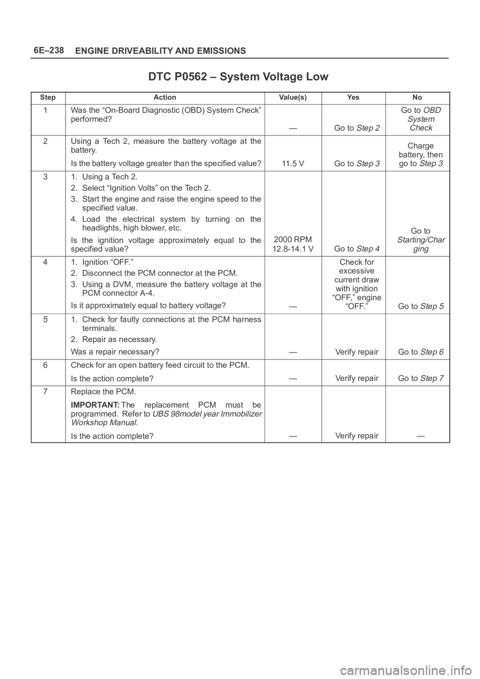
DTC P0562 – System Voltage Low
StepActionVa l u e ( s )Ye sNo
1Was the “On-Board Diagnostic (OBD) System Check”
performed?
—Go to Step 2
Go to OBD
System
Check
2Using a Tech 2, measure the battery voltage at the
battery.
Is the battery voltage greater than the specified value?
11.5 VGo to Step 3
Charge
battery, then
go to
Step 3
31. Using a Tech 2.
2. Select “Ignition Volts” on the Tech 2.
3. Start the engine and raise the engine speed to the
specified value.
4. Load the electrical system by turning on the
headlights, high blower, etc.
Is the ignition voltage approximately equal to the
specified value?
2000 RPM
12.8-14.1 V
Go to Step 4
Go to
Starting/Char
ging
41. Ignition “OFF.”
2. Disconnect the PCM connector at the PCM.
3. Using a DVM, measure the battery voltage at the
PCM connector A-4.
Is it approximately equal to battery voltage?
—
Check for
excessive
current draw
with ignition
“OFF,” engine
“OFF.”
Go to Step 5
51. Check for faulty connections at the PCM harness
terminals.
2. Repair as necessary.
Was a repair necessary?
—Verify repairGo to Step 6
6Check for an open battery feed circuit to the PCM.
Is the action complete?
—Verify repairGo to Step 7
7Replace the PCM.
IMPORTANT:The replacement PCM must be
programmed. Refer to
UBS 98model year Immobilizer
Workshop Manual.
Is the action complete?—Verify repair—
Page 1366 of 6000
6E–249 ENGINE DRIVEABILITY AND EMISSIONS
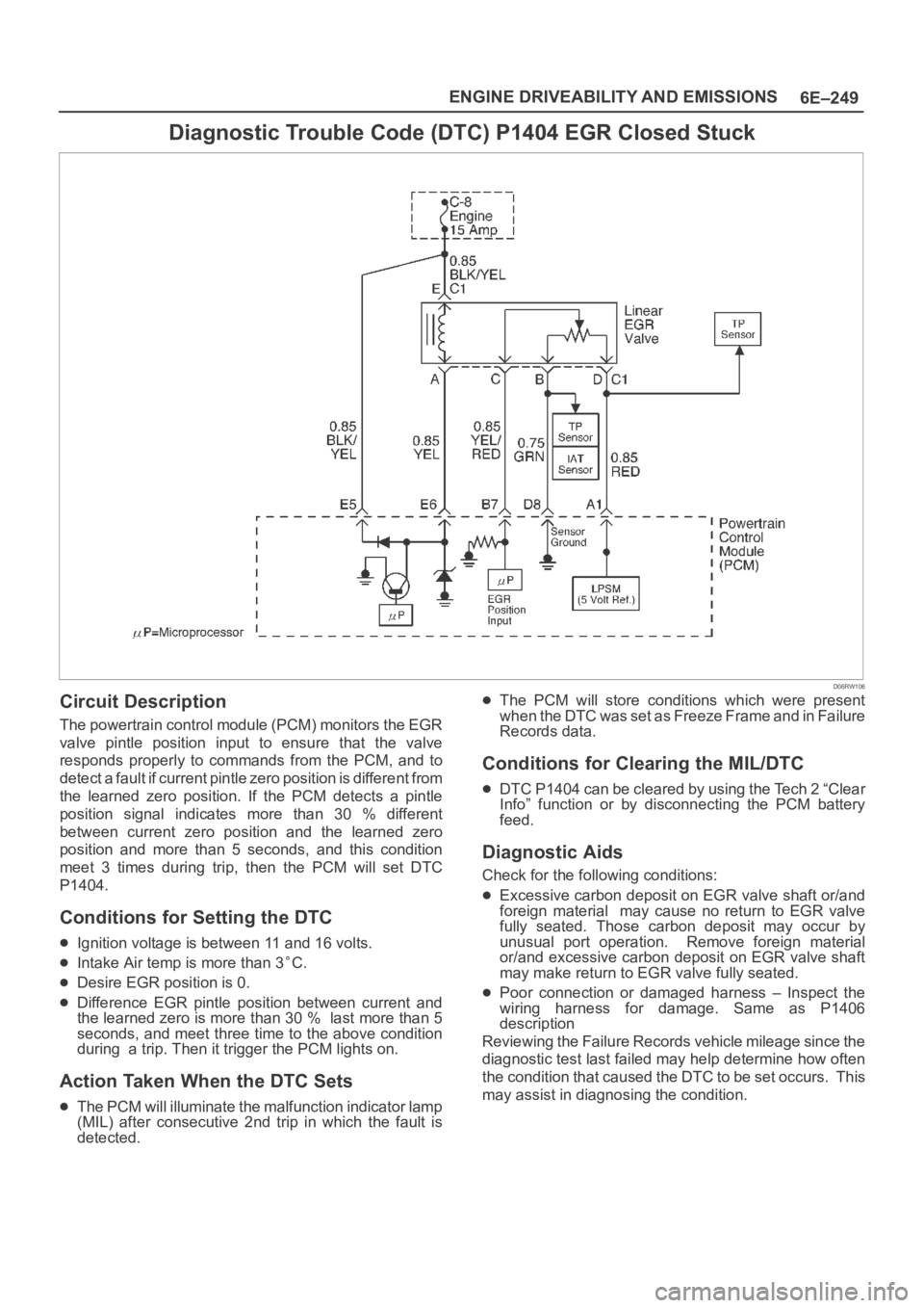
Diagnostic Trouble Code (DTC) P1404 EGR Closed Stuck
D06RW106
Circuit Description
The powertrain control module (PCM) monitors the EGR
valve pintle position input to ensure that the valve
responds properly to commands from the PCM, and to
detect a fault if current pintle zero position is different from
the learned zero position. If the PCM detects a pintle
position signal indicates more than 30 % different
between current zero position and the learned zero
position and more than 5 seconds, and this condition
meet 3 times during trip, then the PCM will set DTC
P1404.
Conditions for Setting the DTC
Ignition voltage is between 11 and 16 volts.
Intake Air temp is more than 3C.
Desire EGR position is 0.
Difference EGR pintle position between current and
the learned zero is more than 30 % last more than 5
seconds, and meet three time to the above condition
during a trip. Then it trigger the PCM lights on.
Action Taken When the DTC Sets
The PCM will illuminate the malfunction indicator lamp
(MIL) after consecutive 2nd trip in which the fault is
detected.
The PCM will store conditions which were present
when the DTC was set as Freeze Frame and in Failure
Records data.
Conditions for Clearing the MIL/DTC
DTC P1404 can be cleared by using the Tech 2 “Clear
Info” function or by disconnecting the PCM battery
feed.
Diagnostic Aids
Check for the following conditions:
Excessive carbon deposit on EGR valve shaft or/and
foreign material may cause no return to EGR valve
fully seated. Those carbon deposit may occur by
unusual port operation. Remove foreign material
or/and excessive carbon deposit on EGR valve shaft
may make return to EGR valve fully seated.
Poor connection or damaged harness – Inspect the
wiring harness for damage. Same as P1406
description
Reviewing the Failure Records vehicle mileage since the
diagnostic test last failed may help determine how often
the condition that caused the DTC to be set occurs. This
may assist in diagnosing the condition.
Page 1369 of 6000
6E–252
ENGINE DRIVEABILITY AND EMISSIONS
passage and on the IAC pintle, and excessive deposits
in the throttle bore and on the throttle plate.
Large vacuum leak – Check for a condition that causes
a large vacuum leak, such as an incorrectly installed or
faulty PCV valve or a disconnected brake booster
hose.Reviewing the Failure Records vehicle mileage since the
diagnostic test last failed may help determine how often
the condition that caused the DTC to be set occurs. This
may assist in diagnosing the condition.
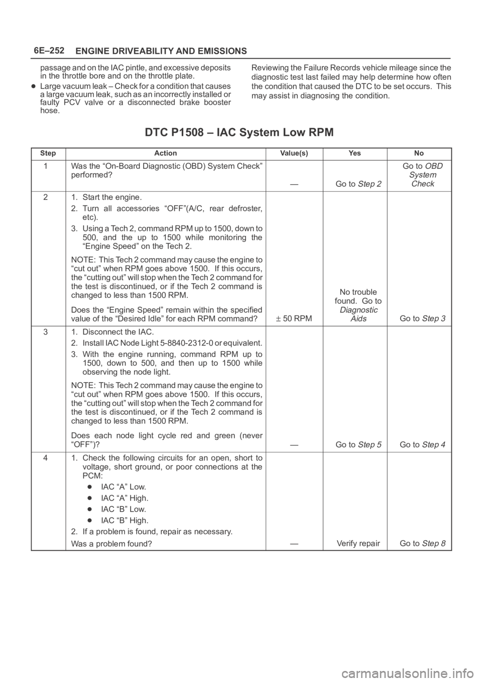
DTC P1508 – IAC System Low RPM
StepActionVa l u e ( s )Ye sNo
1Was the “On-Board Diagnostic (OBD) System Check”
performed?
—Go to Step 2
Go to OBD
System
Check
21. Start the engine.
2. Turn all accessories “OFF”(A/C, rear defroster,
etc).
3. Using a Tech 2, command RPM up to 1500, down to
500, and the up to 1500 while monitoring the
“Engine Speed” on the Tech 2.
NOTE: This Tech 2 command may cause the engine to
“cut out” when RPM goes above 1500. If this occurs,
the “cutting out” will stop when the Tech 2 command for
the test is discontinued, or if the Tech 2 command is
changed to less than 1500 RPM.
Does the “Engine Speed” remain within the specified
value of the “Desired Idle” for each RPM command?
50 RPM
No trouble
found. Go to
Diagnostic
Aids
Go to Step 3
31. Disconnect the IAC.
2. Install IAC Node Light 5-8840-2312-0 or equivalent.
3. With the engine running, command RPM up to
1500, down to 500, and then up to 1500 while
observing the node light.
NOTE: This Tech 2 command may cause the engine to
“cut out” when RPM goes above 1500. If this occurs,
the “cutting out” will stop when the Tech 2 command for
the test is discontinued, or if the Tech 2 command is
changed to less than 1500 RPM.
Does each node light cycle red and green (never
“OFF”)?
—Go to Step 5Go to Step 4
41. Check the following circuits for an open, short to
voltage, short ground, or poor connections at the
PCM:
IAC “A” Low.
IAC “A” High.
IAC “B” Low.
IAC “B” High.
2. If a problem is found, repair as necessary.
Was a problem found?
—Verify repairGo to Step 8
Page 1372 of 6000
6E–255 ENGINE DRIVEABILITY AND EMISSIONS
Throttle body – Check for sticking throttle plate. Also
inspect the IAC passage for deposits or objects which
keep the IAC pintle from fully extending.
Reviewing the Failure Records vehicle mileage since the
diagnostic test last failed may help determine how oftenthe condition that caused the DTC to be set occurs. This
may assist in diagnosing the condition.
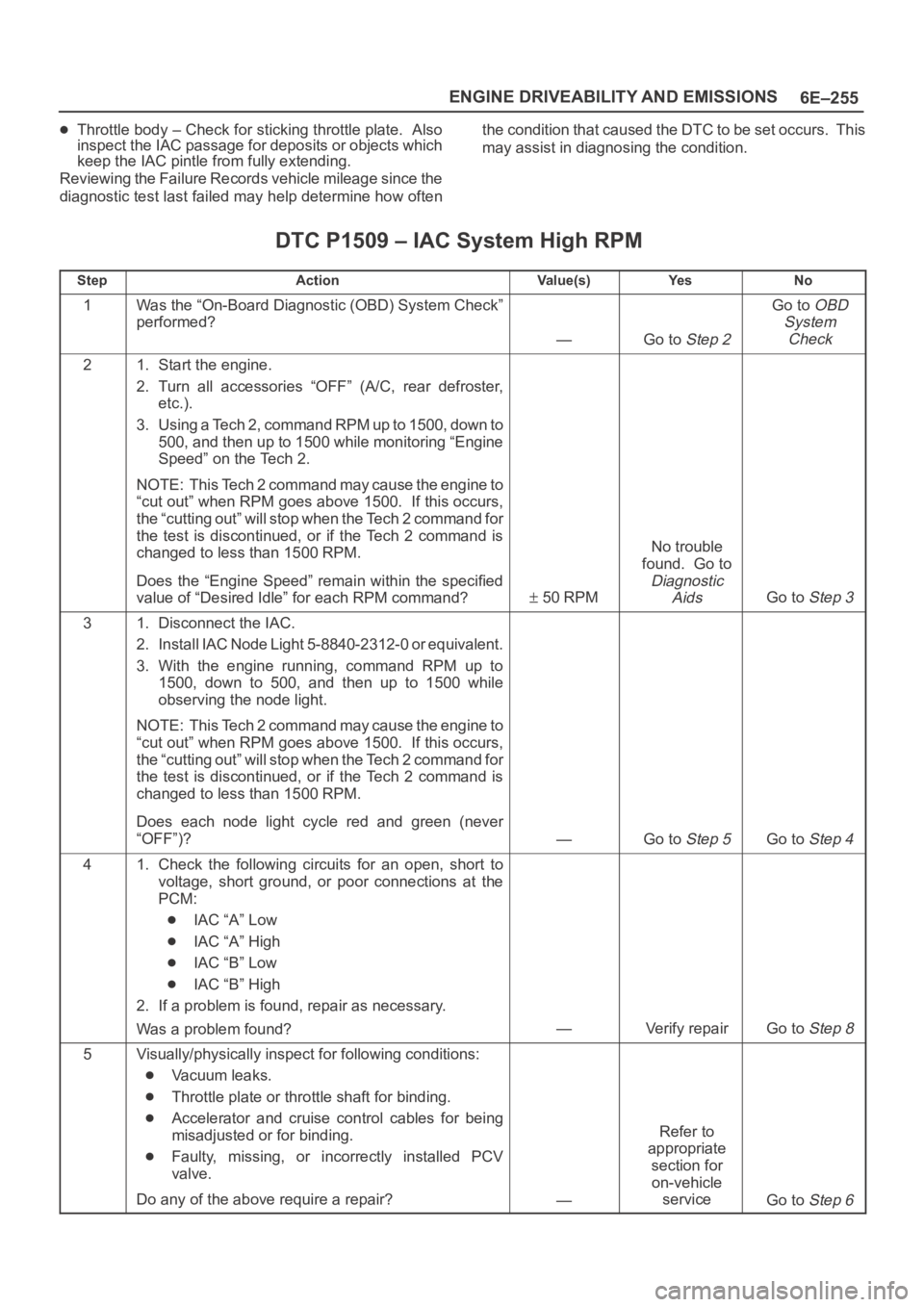
DTC P1509 – IAC System High RPM
StepActionVa l u e ( s )Ye sNo
1Was the “On-Board Diagnostic (OBD) System Check”
performed?
—Go to Step 2
Go to OBD
System
Check
21. Start the engine.
2. Turn all accessories “OFF” (A/C, rear defroster,
etc.).
3. Using a Tech 2, command RPM up to 1500, down to
500, and then up to 1500 while monitoring “Engine
Speed” on the Tech 2.
NOTE: This Tech 2 command may cause the engine to
“cut out” when RPM goes above 1500. If this occurs,
the “cutting out” will stop when the Tech 2 command for
the test is discontinued, or if the Tech 2 command is
changed to less than 1500 RPM.
Does the “Engine Speed” remain within the specified
value of “Desired Idle” for each RPM command?
50 RPM
No trouble
found. Go to
Diagnostic
Aids
Go to Step 3
31. Disconnect the IAC.
2. Install IAC Node Light 5-8840-2312-0 or equivalent.
3. With the engine running, command RPM up to
1500, down to 500, and then up to 1500 while
observing the node light.
NOTE: This Tech 2 command may cause the engine to
“cut out” when RPM goes above 1500. If this occurs,
the “cutting out” will stop when the Tech 2 command for
the test is discontinued, or if the Tech 2 command is
changed to less than 1500 RPM.
Does each node light cycle red and green (never
“OFF”)?
—Go to Step 5Go to Step 4
41. Check the following circuits for an open, short to
voltage, short ground, or poor connections at the
PCM:
IAC “A” Low
IAC “A” High
IAC “B” Low
IAC “B” High
2. If a problem is found, repair as necessary.
Was a problem found?
—Verify repairGo to Step 8
5Visually/physically inspect for following conditions:
Vacuum leaks.
Throttle plate or throttle shaft for binding.
Accelerator and cruise control cables for being
misadjusted or for binding.
Faulty, missing, or incorrectly installed PCV
valve.
Do any of the above require a repair?
—
Refer to
appropriate
section for
on-vehicle
service
Go to Step 6
Page 1375 of 6000
6E–258
ENGINE DRIVEABILITY AND EMISSIONS
Diagnostic Trouble Code (DTC) P1625 PCM Unexpected Reset
Circuit Description
The powertrain control module (PCM) monitors
unexpected PCM reset. This will not turn on MIL light on,
only records code DTC P1625.
Conditions for Setting the DTC
Clock or COP reset.
Action Taken When the DTC Sets
The PCM will not illuminate the malfunction indicator
lamp (MIL).
The PCM will store conditions which were present
when the DTC was set as Failure Records only. This
information will not be stored as Freeze Frame data.
Conditions for Clearing the MIL/DTC
DTC P1625 can be cleared by using the Tech 2 “Clear
Info” function or by disconnecting the PCM battery
feed.
Diagnostic Aids
Check for the following conditions:
P1625 alone stored does not need diagnosis. Clear
DTC code.
Page 1379 of 6000
6E–262
ENGINE DRIVEABILITY AND EMISSIONS
Symptom Diagnosis
Preliminary Checks
Before using this section, perform the “On-Board
Diagnostic (OBD) System Check” and verify all of the
following items:
The powertrain control module (PCM) and malfunction
indicator lamp (MIL) (Service Engine Soon lamp) are
operating correctly.
There are no DTC(s) stored.
Tech 2 data is within normal operating range. Refer to
Typical Scan Data Values.
Verify the customer complaint and locate the correct
symptom in the table of contents. Perform the
procedure included in the symptom chart.
Visual/Physical Check
Several of the symptom procedures call for a careful
visual/physical check. This can lead to correcting a
problem without further checks and can save valuable
time.
This check should include the following items:
PCM grounds for cleanliness, tightness and proper
location.
Vacuum hoses for splits, kinks, and proper
connections, as shown on the “Vehicle Emission
Control Information” label. Check thoroughly for any
type of leak or restriction.
Air intake ducts for collapsed or damaged areas.
Air leaks at throttle body mounting area, mass air flow
(MAF) sensor and intake manifold sealing surfaces.
Ignition wires for cracking, hardness, and carbon
tracking.
Wiring for proper connections, pinches and cuts.
Intermittents
IMPORTANT:An intermittent problem may or may not
turn on the malfunction indicator lamp (MIL) or store a
DTC. DO NOT use the Diagnostic Trouble Code (DTC)
charts for intermittent problems. The fault must be
present to locate the problem.
Most intermittent problems are caused by faulty electrical
connections or wiring. Perform a careful visual/physical
check for the following conditions:
Poor mating of the connector halves or a terminal not
fully seated in the connector (backed out).
Improperly formed or damaged terminal.
All connector terminals in the problem circuit should be
carefully checked for proper contact tension.
Poor terminal-to-wire connection. This requires
removing the terminal from the connector body to
check.
Road test the vehicle with a J 39200 Digital Multimeter
connected to a suspected circuit. An abnormal voltage
when the malfunction occurs is a good indication that
there is a fault in the circuit being monitored.
Use Tech 2 to help detect intermittent conditions. Tech 2s
have several features that can be used to locate anintermittent condition. Use the following feature to find
intermittent faults:
Using Tech 2’s “Freeze Frame” buffer or “Failure
Records” buffer can aid in locating an intermittent
condition. Review and record the information in the
freeze frame or failure record associated with the
intermittent DTC being diagnosed. The vehicle can be
driven within the conditions that were present when the
DTC originally set.
To check for loss of diagnostic code memory, disconnect
the MAP sensor and idle the engine until the MIL (Service
Engine Soon lamp) comes on. DTC P0107 should be
stored and kept in memory when the ignition is turned
“OFF.” If not, the PCM is faulty. When this test is
completed, make sure that you clear the DTC P0107 from
memory.
An intermittent MIL (Service Engine Soon lamp) with no
stored DTC may be caused by the following:
Ignition coil shorted to ground and arcing at ignition
wires or plugs.
MIL (Service Engine Soon lamp) wire to PCM shorted
to ground.
Poor PCM grounds. Refer to the PCM wiring
diagrams.
Check for improper installation of electrical options such
as lights, cellular phones, etc. Route ignition coil wiring
away from the ignition coils. Check all wires from the
PCM to the ignition coil for poor connections.
Check for an open diode across the A/C compressor
clutch and check for other open diodes (refer to wiring
diagrams in
Electrical Diagnosis).
If problem has not been found, refer to
PCM Connector
Symptom
tables.
Page 1415 of 6000
6E–298
ENGINE DRIVEABILITY AND EMISSIONS
4. Remove the MAP sensor from the mounting bracket.
055RW002
Installation Procedure
1. Install the MAP sensor in the mounting bracket.
055RW002
2. Install the mounting bracket retaining bolt on the
common chamber.
3. Connect the MAP electrical connector.
055RW005
4. Connect the negative battery cable.
Malfunction Indicator Lamp
(MIL)
Removal and Installation Procedure
Refer to Warning light bulb, indicator light valve,
illumination light bulb, A/T indicator light bulb in Meter and
Gauge.
Powertrain Control Module
(PCM)
Service Precaution
NOTE: To prevent possible electrostatic discharge
damage to the PCM, do not touch the connector pins or
soldered components on the circuit board.
Electrostatic Discharge (ESD)
Damage
Electronic components used in the control systems are
often designed to carry very low voltage. Electronic
components are susceptible to damage caused by
electrostatic discharge. Less than 100 volts of static
electricity can cause damage to some electronic
components. By comparison, it takes as much as 4,000
volts for a person to even feel the zap of a static
discharge.
There are several ways for a person to become statically
charged. The most common methods of charging are by
friction and by induction. An example of charging by
friction is a person sliding across a car seat.
Charging by induction occurs when a person with well
insulated shoes stands near a highly charged object and
momentarily touches ground. Charges of the same
polarity are drained off leaving the person highly charged
with the opposite polarity. Static charges can cause
Page 1419 of 6000
6E–302
ENGINE DRIVEABILITY AND EMISSIONS
2. Connect the TP electrical connector.
3. Install the negative battery cable.
Vehicle Speed Sensor (VSS)
Removal Procedure
CAUTION: The VSS is located on the right side of
the transfer case just ahead of the rear propeller
shaft and very close to the exhaust pipes. Be sure
that the exhaust pipes are cool enough to touch
before trying to remove the VSS. If the pipes are hot,
you could be burned.
1. Disconnect the negative battery cable.
2. Disconnect the VSS electrical connector.
TS23748
3. Remove the bolt and the clamp securing the VSS in
place.
IMPORTANT:H a v e a c o n t a i n e r r e a d y t o c a t c h a n y f l u i d
that leaks out when the VSS is removed from the transfer
case.
TS23780
4. Remove the VSS from the transfer case by wiggling it
slightly and pulling it straight out.
Inspection Procedure
1. Inspect the electrical connector for signs of corrosion
or warping. Replace the VSS if the electrical
connector is corroded or warped.
2. Inspect the VSS driven gear for chips, breaks, or worn
condition. Replace the VSS if the driven gear is
chipped, broken or worn.
3. Inspect the O-ring for wear, nicks, tears, or
looseness. Replace the O-ring if necessary.
Installation Procedure
1. Install the VSS in the transfer case with the notch for
the connector facing the rear.
2. Secure the VSS in place with the clamp and the bolt.
Tighten
Tighten the bolt to 16 Nꞏm (12 lb ft.).
TS23780
3. Connect the VSS electrical connector.
TS23748