Page 4971 of 6000

6E–314
ENGINE DRIVEABILITY AND EMISSIONS
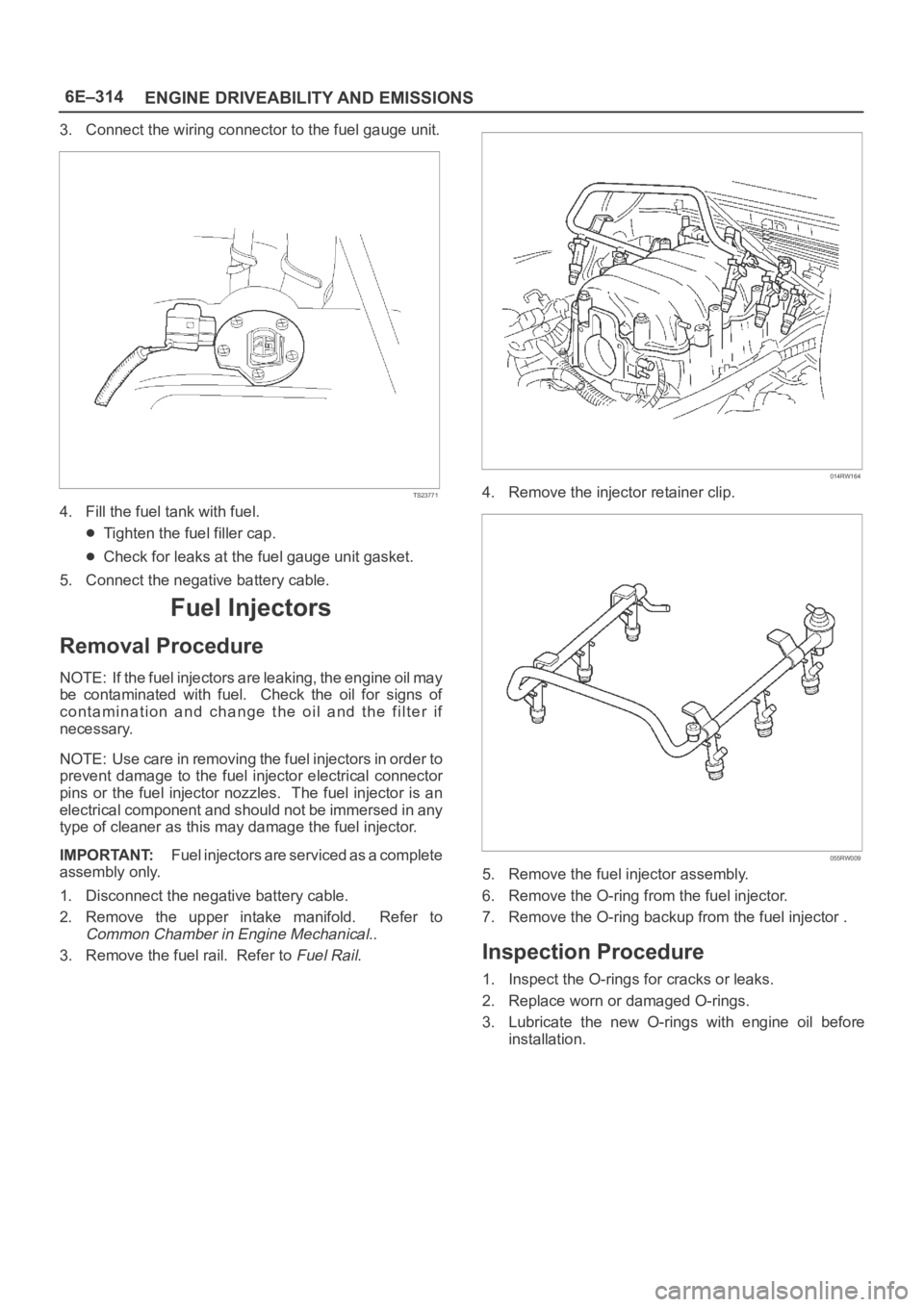
3. Connect the wiring connector to the fuel gauge unit.
TS23771
4. Fill the fuel tank with fuel.
Tighten the fuel filler cap.
Check for leaks at the fuel gauge unit gasket.
5. Connect the negative battery cable.
Fuel Injectors
Removal Procedure
NOTE: If the fuel injectors are leaking, the engine oil may
be contaminated with fuel. Check the oil for signs of
contamination and change the oil and the filter if
necessary.
NOTE: Use care in removing the fuel injectors in order to
prevent damage to the fuel injector electrical connector
pins or the fuel injector nozzles. The fuel injector is an
electrical component and should not be immersed in any
type of cleaner as this may damage the fuel injector.
IMPORTANT:Fuel injectors are serviced as a complete
assembly only.
1. Disconnect the negative battery cable.
2. Remove the upper intake manifold. Refer to
Common Chamber in Engine Mechanical..
3. Remove the fuel rail. Refer to
Fuel Rail.
014RW164
4. Remove the injector retainer clip.
055RW009
5. Remove the fuel injector assembly.
6. Remove the O-ring from the fuel injector.
7. Remove the O-ring backup from the fuel injector .
Inspection Procedure
1. Inspect the O-rings for cracks or leaks.
2. Replace worn or damaged O-rings.
3. Lubricate the new O-rings with engine oil before
installation.
Page 5275 of 6000

6A – 2 ENGINE MECHANICAL
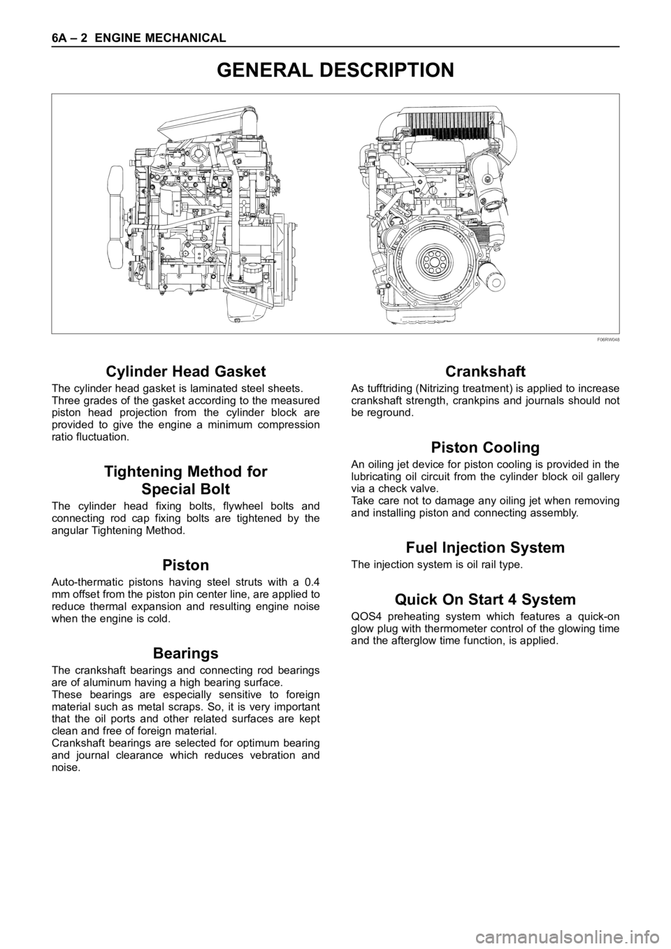
GENERAL DESCRIPTION
Cylinder Head Gasket
The cylinder head gasket is laminated steel sheets.
Three grades of the gasket according to the measured
piston head projection from the cylinder block are
provided to give the engine a minimum compression
ratio fluctuation.
Tightening Method for
Special Bolt
The cylinder head fixing bolts, flywheel bolts and
connecting rod cap fixing bolts are tightened by the
angular Tightening Method.
Piston
Auto-thermatic pistons having steel struts with a 0.4
mm offset from the piston pin center line, are applied to
reduce thermal expansion and resulting engine noise
when the engine is cold.
Bearings
The crankshaft bearings and connecting rod bearings
are of aluminum having a high bearing surface.
These bearings are especially sensitive to foreign
material such as metal scraps. So, it is very important
that the oil ports and other related surfaces are kept
clean and free of foreign material.
Crankshaft bearings are selected for optimum bearing
and journal clearance which reduces vebration and
noise.
Crankshaft
As tufftriding (Nitrizing treatment) is applied to increase
crankshaft strength, crankpins and journals should not
be reground.
Piston Cooling
An oiling jet device for piston cooling is provided in the
lubricating oil circuit from the cylinder block oil gallery
via a check valve.
Take care not to damage any oiling jet when removing
and installing piston and connecting assembly.
Fuel Injection System
The injection system is oil rail type.
Quick On Start 4 System
QOS4 preheating system which features a quick-on
glow plug with thermometer control of the glowing time
and the afterglow time function, is applied.
F06RW048
Page 5276 of 6000

ENGINE MECHANICAL 6A – 3
SERVICE INFORMATION
MAIN DATA AND SPECIFICATION
Engine type Diesel, four cycle water cooled inline
Camshaft type DOHC
Number of cylinders 4
Bore x stroke (mm) 95.4 x 104.9
Total piston displacement (cc) 2999
Compression ratio (to 1) 19.0
Engine weight (dry) N (kg/lb) 2492 (254/560) (A/T)
2649 (270/593) (M/T)
Engine idling speed (Reference) RPM 720
Compression pressure kpa (kg/cm
2/psi)-rpm 3000 (31/440)-200
Firing order 1–3–4–2
VALVE SYSTEM
Intake valves open at: B.T.D.C. 3°
close at: A.B.D.C. 57.6°
Exhaust valves open at: B.B.D.C. 56.5°
close at: A.T.D.C. 5°
Valve clearance at cold mm (in)
intake: 0.15 (0.006)
exhaust: 0.25 (0.01)
Oil filter Full flow and bypass combined type
Oil capacity (Original factory fill or rebuilt engine) 9.0 liters (7.9 US quarts)
Oil capacity (Service change)
with filter change 6.0 liters (6.3 US quarts)
without filter change 5.0 liters (5.3 US quarts)
Oil cooler Water cooled type
Inter cooler Air cooled type
Turbocharger method
Control method Wastegate control
Lubrication Pressurized control
Cooling method Coolant cooled
Page 5282 of 6000

ENGINE MECHANICAL 6A – 9
SERVICING
Servicing refers to general maintenance procedures to
be performed by qualified service personnel.
MODEL IDENTIFICATION
Engine Serial Number
The engine number is stamped on the rear left hand
side of the cylinder body.
AIR CLEANER
Oil Wetted (Viscous) Type Paper Element.
The air cleaner has an oil wetted paper element. No
servicing is required until the replacement interval is
reached.
Never attempt to clean the element, no matter how dirty
it may appear. The element is designed to provide
normal filtering efficiency until it becomes due for
replacement.
Refer to the Item “Service and Maintenance” in the
Owner’s and Driver’s Manual for general service
information.
LUBRICATING SYSTEM
Main Oil Filter (Cartridge Type Paper Element)
Replacement Procedure
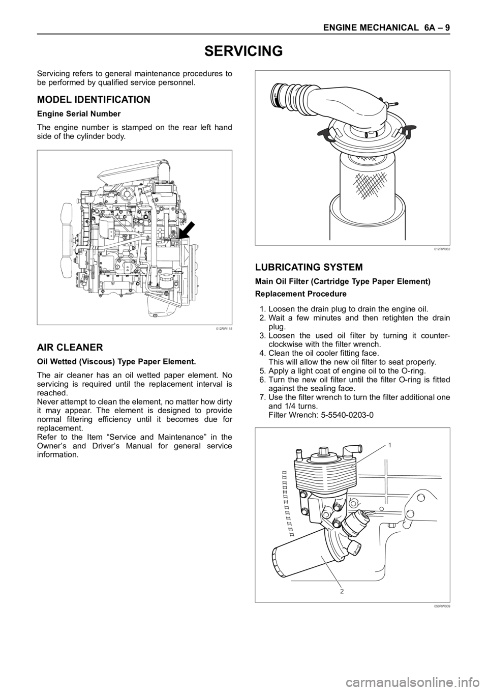
1. Loosen the drain plug to drain the engine oil.
2. Wait a few minutes and then retighten the drain
plug.
3. Loosen the used oil filter by turning it counter-
clockwise with the filter wrench.
4. Clean the oil cooler fitting face.
This will allow the new oil filter to seat properly.
5. Apply a light coat of engine oil to the O-ring.
6. Turn the new oil filter until the filter O-ring is fitted
against the sealing face.
7. Use the filter wrench to turn the filter additional one
and 1/4 turns.
Filter Wrench: 5-5540-0203-0
012RW115
012RW062
1
2
050RW009
Page 5371 of 6000
6B – 2 ENGINE COOLING
Legend
(1) Turbocharger
(2) Thermostat
(3) Reservoir Tank
(4) Radiator
(5) Bypass(6) Oil Cooler
(7) Cooling fan
(8) Water Pump
(9) Thermo Valve
(10) Car Heater
GENERAL DESCRIPTION
COOLANT FLOW
1
6
9
10
8
4
325
7
032RW001
The cooling system is a pressurized coolant forced
circulation type which consists of water pump,
thermostat, cooling fan, radiator and other components. The circulating coolant cools the lubricating oil in the oil
cooler and turbocharger.
Page 5372 of 6000
ENGINE COOLING 6B – 3
WAT E R P U M P
The coolant pump is a centrifugal impeller type and is
driven by V type drive belt.
Legend
(1) Roller Bearing
(2) Ball Bearing
(3) Seal Unit
THERMOSTAT
The thermostat is a wax pellet type with a jiggle valve
and is installed in the thermostat housing.
Legend
(1) Bolt
(2) Thermostat Housing
(3) Thermostat
(4) Intake Manifold
RADIATOR
The radiator is a tube type with corrugated fins. In order
to raise the boiling point of coolant, the radiator is fitted
with a cap in which the valve is operated under the
pressure.
1
3 2
PCD 60
A06RW024
1
2
3
4
032RW002
110RS001
Page 5387 of 6000
6C – 6 ENGINE FUEL
FUEL FILTER
Legend
(1) Priming Pump
(2) Fuel Filter Cartridge
A cartridge type fuel filter is used along with the piston
type fuel pump on the high pressure oil pump.
The fuel filter removes foreign material from the fuel
before it reaches the fuel pump.
A diaphragm type priming pump is installed at the top of
the fuel filter. It is used during the air bleeding
procedures.
INJECTOR ASSEMBLY
Legend
(1) Oil Passage
(2) Fuel Passage
1. Construction of Fuel Injector
The fuel injector is comprised of the solenoid
section, hydraulic line, and fuel line. Fuel injection is
controlled by the continuity time signal and
continuity start timing signal sent by the ECM
(Electronic Control Module) to the solenoid.
2. Working of Fuel Injector
1) The ECM detects the working of the engine from
its input signals, such as engine speed
accelerator throttle opening, and engine coolant
temperature, sending the optimal signals to the
solenoid.
1
2
041RW017
1
2
055RW018
Page 5418 of 6000
ENGINE ELECTRICAL 6D – 15
CHARGING SYSTEM
GENERAL DESCRIPTION
GENERATOR
CHARGING CIRCUIT
The charging system is the IC integral regulator
charging system and its main components are
connected as shown in Figure.
The regulator is a solid state type and it is mounted
along with the brush holder assembly inside the
generator installed on the rear end cover.The generator does not require particular maintenance
such as voltage adjustment. The rectifier connected to
the stator coil has nine diodes to transform A.C. voltage
into D.C. voltage. This D.C. voltage is connected to the
output terminal of generator.
A06RW001
Condenser
GeneratorStator Coil
IC RegulatorStarter
SW
Rotor Coil
Battery
P F
EBS LRelay B
S
L
QOS
C/U
065RW00001