1998 OPEL FRONTERA oil type
[x] Cancel search: oil typePage 5455 of 6000
6E–26
4JX1–TC ENGINE DRIVEABILITY AND EMISSIONS
Output Components:
Output components are diagnosed for proper response to
control module commands. Components where
functional monitoring is not feasible will be monitored for
circuit continuity and out-of-range values if applicable.
Output components to be monitored include, but are not
limited to, the following circuit:
EGR VSV
EGR EVRV
Electronic Transmission controls
Injector
Intake throttle
Glow plug
MIL control
Refer to ECM and Sensors in General Descriptions.
Passive and Active Diagnostic Tests
A passive test is a diagnostic test which simply monitors a
vehicle system or component. Conversely, an active test,
actually takes some sort of action when performing
diagnostic functions, often in response to a failed passive
test.
Intrusive Diagnostic Tests
This is any on-board test run by the Diagnostic
Management System which may have an effect on
vehicle performance or emission levels.
Warm-Up Cycle
A warm-up cycle means that engine at temperature must
reach a minimum of 70
C (160F) and rise at least 22C
(40
F) over the course of a trip.
Freeze Frame
Freeze Frame is an element of the Diagnostic
Management System which stores various vehicle
information at the moment an emissions-related fault is
stored in memory and when the MIL is commanded on.
These data can help to identify the cause of a fault. Refer
to
Storing And Erasing Freeze Fame Data for more
detailed information.
Failure Records
Failure Records data is an enhancement of the OBD
Freeze Frame feature. Failure Records store the same
vehicle information as does Freeze Frame, but it will store
that information for any fault which is stored in on-board
memory, while Freeze Frame stores information only for
emission-related faults that command the MIL on.
Common OBD Terms
Diagnostic
When used as a noun, the word diagnostic refers to any
on-board test run by the vehicle’s Diagnostic
Management System. A diagnostic is simply a test run on
a system or component to determine if the system or
component is operating according to specification. There
are many diagnostics, shown in the following list:
EGR
engine speed
vehicle speed
ECT
MAP
VSV
IAT
ITP
AP
FT (Fuel Temp)
RP (Rail Pressure)
OT (Oil Temp)
EGR EVRV
Idle SW
Brake SW
The Diagnostic Executive
The Diagnostic Executive is a unique segment of
software which is designed to coordinate and prioritize
the diagnostic procedures as well as define the protocol
for recording and displaying their results. The main
responsibilities of the Diagnostic Executive are listed as
follows:
Commanding the MIL (“Check Engine” lamp) on and
off
DTC logging and clearing
Freeze Frame data for the first emission related DTC
recorded
Current status information on each diagnostic
Diagnostic Information
The diagnostic charts and functional checks are designed
to locate a faulty circuit or component through a process
of logical decisions. The charts are prepared with the
requirement that the vehicle functioned correctly at the
time of assembly and that there are not multiple faults
present.
There is a continuous self-diagnosis on certain control
functions. This diagnostic capability is complemented by
the diagnostic procedures contained in this manual. The
language of communicating the source of the malfunction
is a system of diagnostic trouble codes. When a
malfunction is detected by the control module, a
diagnostic trouble code is set and the Malfunction
Indicator Lamp (MIL) (“Check Engine” lamp) is
illuminated.
Malfunction Indicator Lamp (MIL)
The Malfunction Indicator Lamp (MIL) looks the same as
the MIL you are already familiar with “Check Engine”
lamp.
Basically, the MIL is turned on when the ECM detects a
DTC that will impact the vehicle emissions.
When the MIL remains “ON” while the engine is
running, or when a malfunction is suspected due to a
driveability or emissions problem, a Powertrain
On-Board Diagnostic (OBD) System Check must be
performed. The procedures for these checks are
given in On-Board Diagnostic (OBD) System Check.
These checks will expose faults which may not be
detected if other diagnostics are performed first.
DTC Types
Characteristic of Code
Page 5464 of 6000
6E–35 4JX1–TC ENGINE DRIVEABILITY AND EMISSIONS
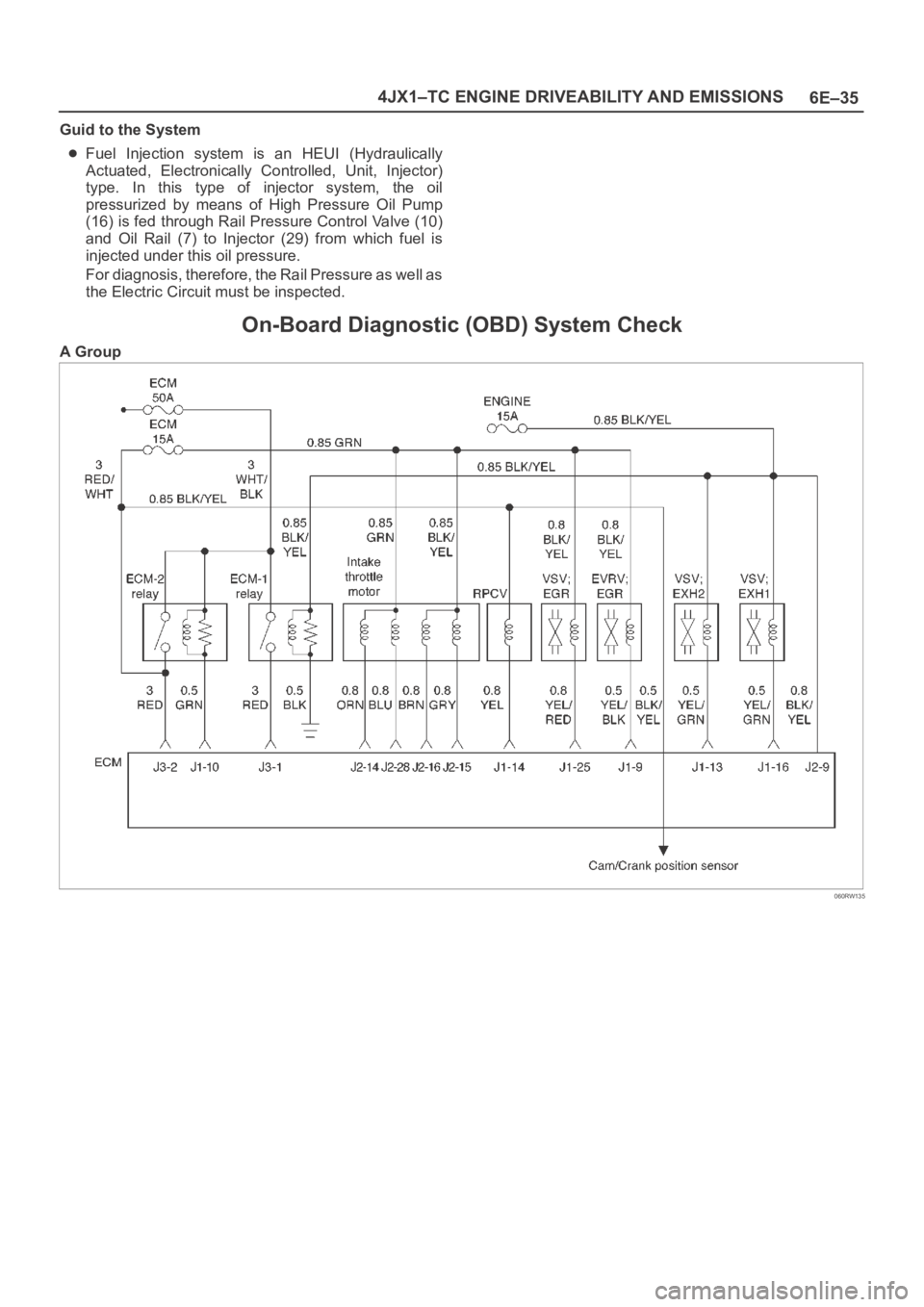
Guid to the System
Fuel Injection system is an HEUI (Hydraulically
Actuated, Electronically Controlled, Unit, Injector)
type. In this type of injector system, the oil
pressurized by means of High Pressure Oil Pump
(16) is fed through Rail Pressure Control Valve (10)
and Oil Rail (7) to Injector (29) from which fuel is
injected under this oil pressure.
For diagnosis, therefore, the Rail Pressure as well as
the Electric Circuit must be inspected.
On-Board Diagnostic (OBD) System Check
A Group
060RW135
Page 5478 of 6000
6E–49 4JX1–TC ENGINE DRIVEABILITY AND EMISSIONS
Engine Cranks But Will Not Run
Circuit Description
In this type of injector system, the Engine Control Module
(ECM) triggers the correct driver inside the injector, which
then triggers the correct injector based on the 57X signal
received from the crankshaft position sensor (CKP).
During crank, the ECM monitors the CKP 57X signal. The
CKP signal is used to determine which cylinder will fire
first. After the CKP 57X signal has been processed by the
ECM, it will command all four injectors to allow a priming
shot of fuel for all the cylinders. After the priming, the
injectors are left “OFF” during the next four 57X reference
pulses from the CKP. This allows each cylinder a chance
to use the fuel from the priming shot. During this waiting
period, a camshaft position (CMP) signal pulse will have
been received by the ECM. The CMP signal allows the
ECM to operate the injectors sequentially based on
camshaft position. If the camshaft position signal is not
present at start-up, the ECM will begin sequential fuel
delivery with a 1-in-4 chance that fuel delivery is correct.
The engine will run without a CMP signal, but will set a
DTC code.
Diagnostic Aids
An intermittent problem may be caused by a poor
connection, rubbed-through wire insulation or a wirebroken inside the insulation. Check for the following
items:
Poor connection or damaged harness – Inspect the
ECM harness and connectors for improper mating,
broken locks, improperly formed or damaged
terminals, poor terminal-to-wore connection, and
damaged harness.
Faulty engine coolant temperature sensor – Using a
Tech 2, compare engine coolant temperature with
manifold air temperature on a completely cool engine.
Test Description
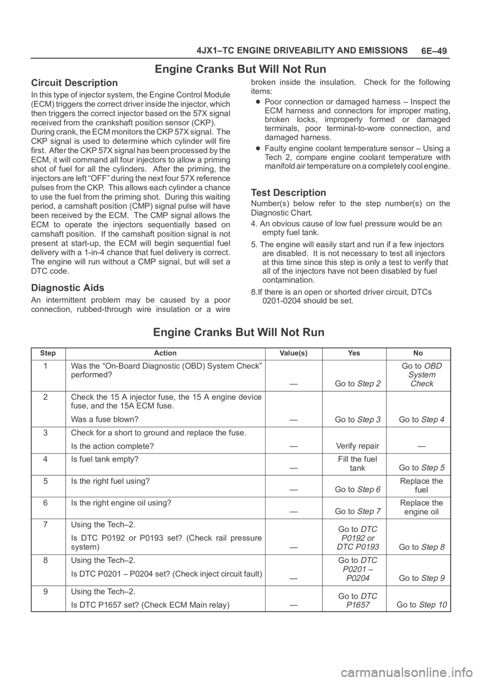
Number(s) below refer to the step number(s) on the
Diagnostic Chart.
4. An obvious cause of low fuel pressure would be an
empty fuel tank.
5. The engine will easily start and run if a few injectors
are disabled. It is not necessary to test all injectors
at this time since this step is only a test to verify that
all of the injectors have not been disabled by fuel
contamination.
8.If there is an open or shorted driver circuit, DTCs
0201-0204 should be set.
Engine Cranks But Will Not Run
StepActionVa l u e ( s )Ye sNo
1Was the “On-Board Diagnostic (OBD) System Check”
performed?
—Go to Step 2
Go to OBD
System
Check
2Check the 15 A injector fuse, the 15 A engine device
fuse, and the 15A ECM fuse.
Was a fuse blown?
—Go to Step 3Go to Step 4
3Check for a short to ground and replace the fuse.
Is the action complete?
—Verify repair—
4Is fuel tank empty?
—
Fill the fuel
tank
Go to Step 5
5Is the right fuel using?
—Go to Step 6
Replace the
fuel
6Is the right engine oil using?
—Go to Step 7
Replace the
engine oil
7Using the Tech–2.
Is DTC P0192 or P0193 set? (Check rail pressure
system)
—
Go to DTC
P0192 or
DTC P0193
Go to Step 8
8Using the Tech–2.
Is DTC P0201 – P0204 set? (Check inject circuit fault)
—
Go to DTC
P0201 –
P0204
Go to Step 9
9Using the Tech–2.
Is DTC P1657 set? (Check ECM Main relay)
—
Go to DTC
P1657
Go to Step 10
Page 5794 of 6000
AUTOMATIC TRANSMISSION (AW30-40LE) 7A–13
DIAGNOSIS
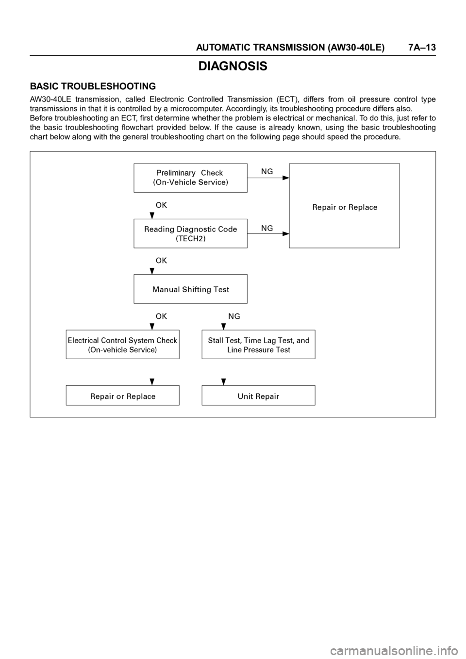
BASIC TROUBLESHOOTING
AW30-40LE transmission, called Electronic Controlled Transmission (ECT), differs from oil pressure control type
transmissions in that it is controlled by a microcomputer. Accordingly, its troubleshooting procedure differs also.
Before troubleshooting an ECT, first determine whether the problem is electrical or mechanical. To do this, just refer to
the basic troubleshooting flowchart provided below. If the cause is already known, using the basic troubleshooting
chart below along with the general troubleshooting char t on the following page should speed the procedure.
Page 5817 of 6000
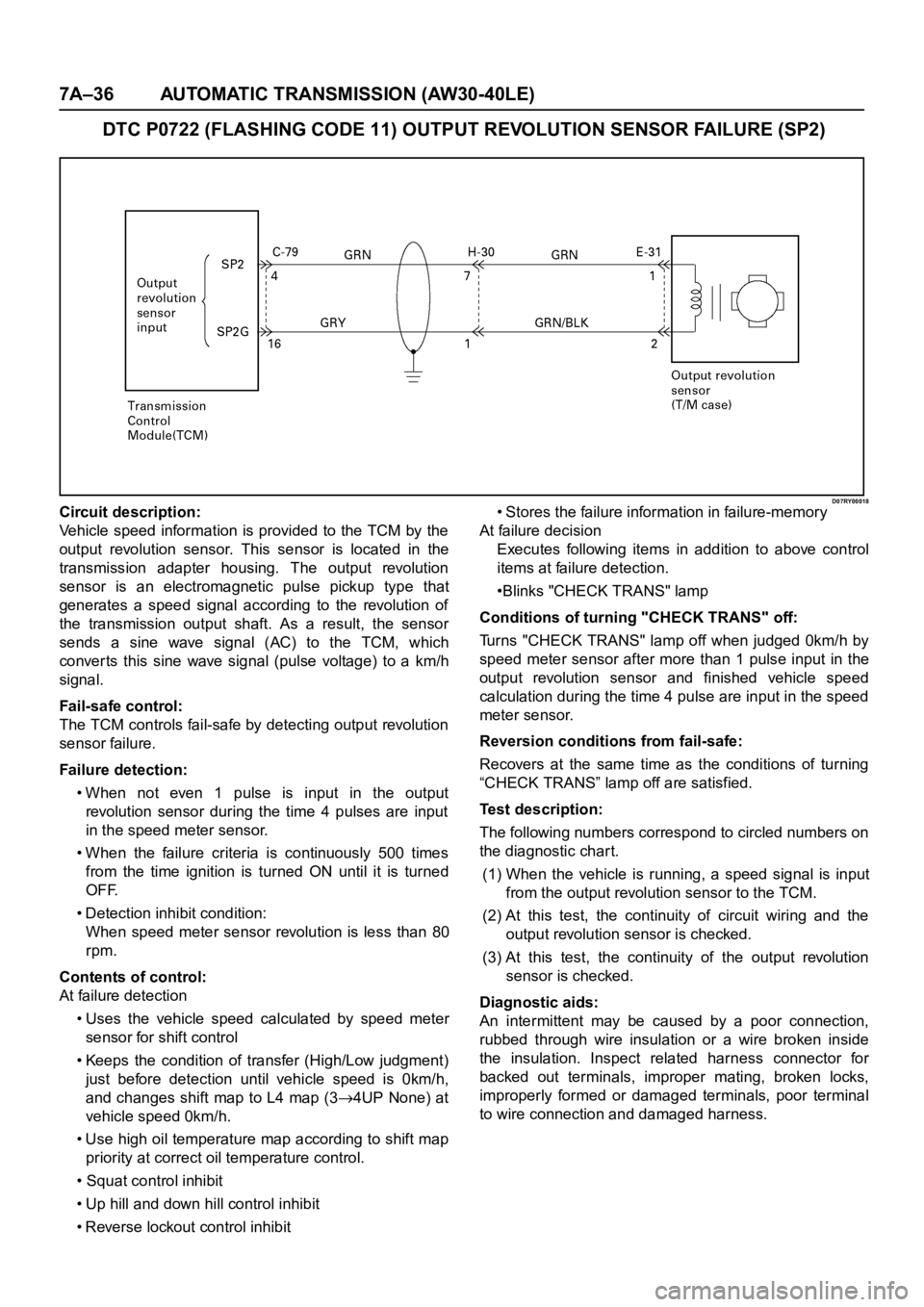
7A–36 AUTOMATIC TRANSMISSION (AW30-40LE)
DTC P0722 (FLASHING CODE 11) OUTPUT REVOLUTION SENSOR FAILURE (SP2)
D07RY00018Circuit description:
Vehicle speed information is provided to the TCM by the
output revolution sensor. This sensor is located in the
transmission adapter housing. The output revolution
sensor is an electromagnetic pulse pickup type that
generates a speed signal according to the revolution of
the transmission output shaft. As a result, the sensor
sends a sine wave signal (AC) to the TCM, which
converts this sine wave signal (pulse voltage) to a km/h
signal.
Fail-safe control:
The TCM controls fail-safe by detecting output revolution
sensor failure.
Failure detection:
• When not even 1 pulse is input in the output
revolution sensor during the time 4 pulses are input
in the speed meter sensor.
• When the failure criteria is continuously 500 times
from the time ignition is turned ON until it is turned
OFF.
• Detection inhibit condition:
When speed meter sensor revolution is less than 80
rpm.
Contents of control:
At failure detection
• Uses the vehicle speed calculated by speed meter
sensor for shift control
• Keeps the condition of transfer (High/Low judgment)
just before detection until vehicle speed is 0km/h,
and changes shift map to L4 map (3
4UP None) at
vehicle speed 0km/h.
• Use high oil temperature map according to shift map
priority at correct oil temperature control.
• Squat control inhibit
• Up hill and down hill control inhibit
• Reverse lockout control inhibit• Stores the failure information in failure-memory
At failure decision
Executes following items in addition to above control
items at failure detection.
•Blinks "CHECK TRANS" lamp
Conditions of turning "CHECK TRANS" off:
Turns "CHECK TRANS" lamp off when judged 0km/h by
speed meter sensor after more than 1 pulse input in the
output revolution sensor and finished vehicle speed
calculation during the time 4 pulse are input in the speed
meter sensor.
Reversion conditions from fail-safe:
Recovers at the same time as the conditions of turning
“CHECK TRANS” lamp off are satisfied.
Test description:
The following numbers correspond to circled numbers on
the diagnostic char t.
(1) When the vehicle is running, a speed signal is input
from the output revolution sensor to the TCM.
(2) At this test, the continuity of circuit wiring and the
output revolution sensor is checked.
(3) At this test, the continuity of the output revolution
sensor is checked.
Diagnostic aids:
An intermittent may be caused by a poor connection,
rubbed through wire insulation or a wire broken inside
the insulation. Inspect related harness connector for
backed out terminals, improper mating, broken locks,
improperly formed or damaged terminals, poor terminal
to wire connection and damaged harness.
Page 5819 of 6000
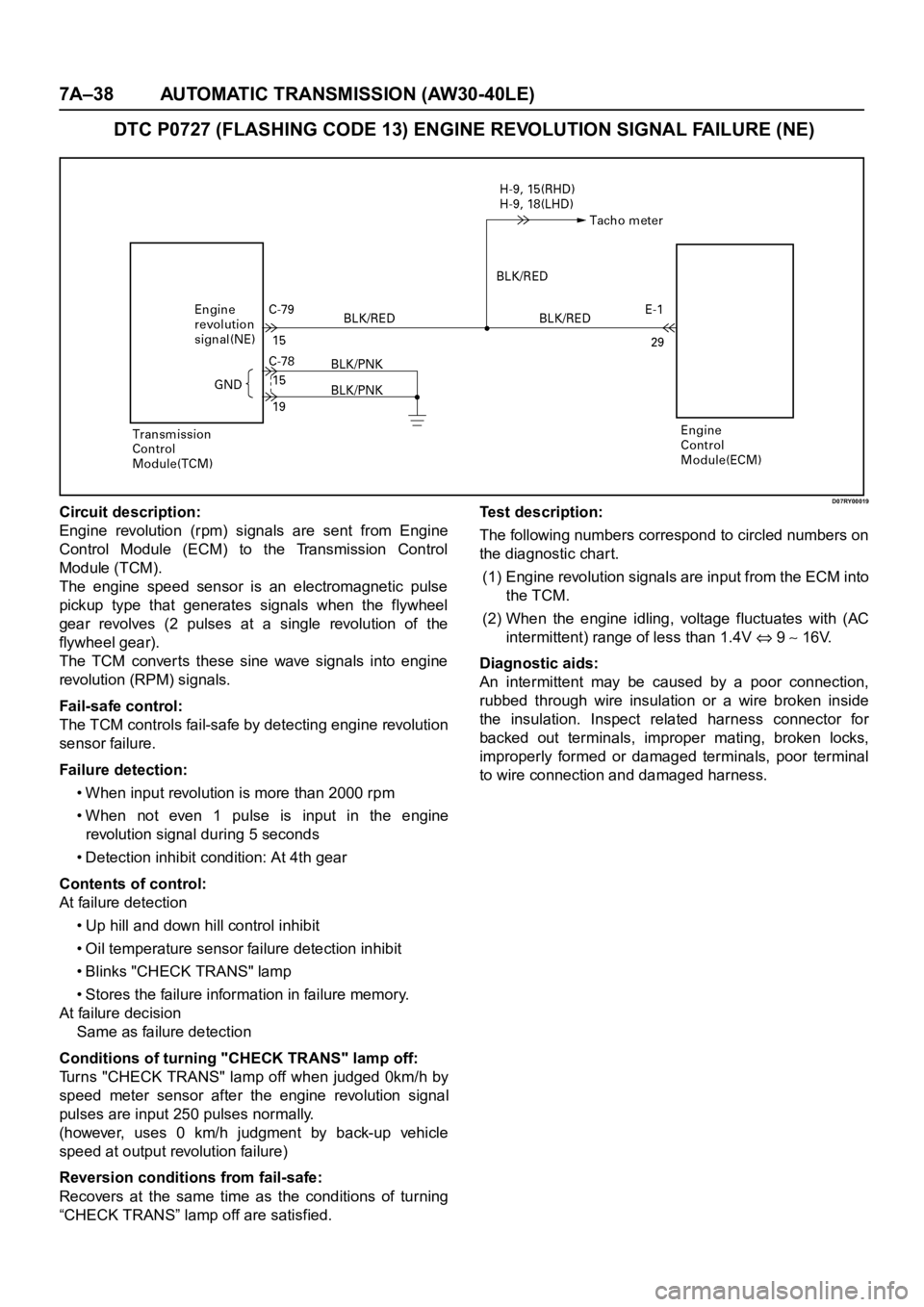
7A–38 AUTOMATIC TRANSMISSION (AW30-40LE)
DTC P0727 (FLASHING CODE 13) ENGINE REVOLUTION SIGNAL FAILURE (NE)
D07RY00019Circuit description:
Engine revolution (rpm) signals are sent from Engine
Control Module (ECM) to the Transmission Control
Module (TCM).
The engine speed sensor is an electromagnetic pulse
pickup type that generates signals when the flywheel
gear revolves (2 pulses at a single revolution of the
flywheel gear).
The TCM converts these sine wave signals into engine
revolution (RPM) signals.
Fail-safe control:
The TCM controls fail-safe by detecting engine revolution
sensor failure.
Failure detection:
• When input revolution is more than 2000 rpm
• When not even 1 pulse is input in the engine
revolution signal during 5 seconds
• Detection inhibit condition: At 4th gear
Contents of control:
At failure detection
• Up hill and down hill control inhibit
• Oil temperature sensor failure detection inhibit
• Blinks "CHECK TRANS" lamp
• Stores the failure information in failure memory.
At failure decision
Same as failure detection
Conditions of turning "CHECK TRANS" lamp off:
Turns "CHECK TRANS" lamp off when judged 0km/h by
speed meter sensor after the engine revolution signal
pulses are input 250 pulses normally.
(however, uses 0 km/h judgment by back-up vehicle
speed at output revolution failure)
Reversion conditions from fail-safe:
Recovers at the same time as the conditions of turning
“CHECK TRANS” lamp off are satisfied.Test description:
The following numbers correspond to circled numbers on
the diagnostic char t.
(1) Engine revolution signals are input from the ECM into
the TCM.
(2) When the engine idling, voltage fluctuates with (AC
intermittent) range of less than 1.4V
9 16V.
Diagnostic aids:
An intermittent may be caused by a poor connection,
rubbed through wire insulation or a wire broken inside
the insulation. Inspect related harness connector for
backed out terminals, improper mating, broken locks,
improperly formed or damaged terminals, poor terminal
to wire connection and damaged harness.
Page 5859 of 6000
7A–78 AUTOMATIC TRANSMISSION (AW30-40LE)
F07RY00019
225RY00001
220RY00001
244RX00001
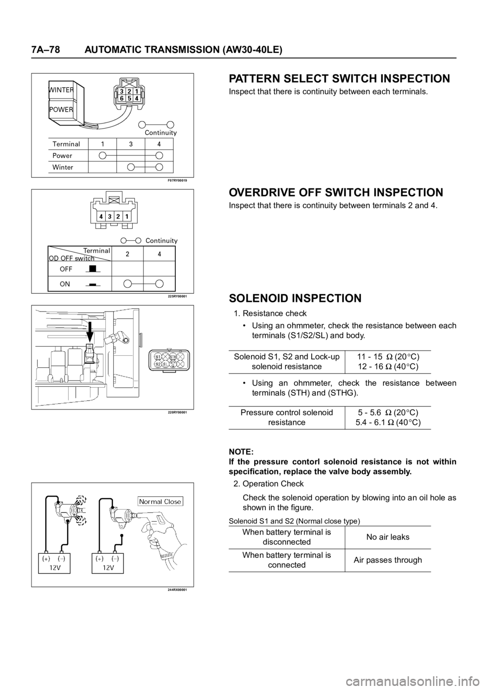
PATTERN SELECT SWITCH INSPECTION
Inspect that there is continuity between each terminals.
OVERDRIVE OFF SWITCH INSPECTION
Inspect that there is continuity between terminals 2 and 4.
SOLENOID INSPECTION
1. Resistance check
• Using an ohmmeter, check the resistance between each
terminals (S1/S2/SL) and body.
• Using an ohmmeter, check the resistance between
terminals (STH) and (STHG).
NOTE:
If the pressure contorl solenoid resistance is not within
specification, replace the valve body assembly.
2. Operation Check
Check the solenoid operation by blowing into an oil hole as
shown in the figure.
Solenoid S1 and S2 (Normal close type)
Solenoid S1, S2 and Lock-up
solenoid resistance11 - 15(20C)
12 - 16
(40C)
Pressure control solenoid
resistance5 - 5.6
(20C)
5.4 - 6.1
(40C)
When battery terminal is
disconnectedNo air leaks
When battery terminal is
connectedAir passes through
Page 5875 of 6000
7A–94 AUTOMATIC TRANSMISSION (AW30-40LE)
240RY00006
240RY00007
240RY00008
244RY00003
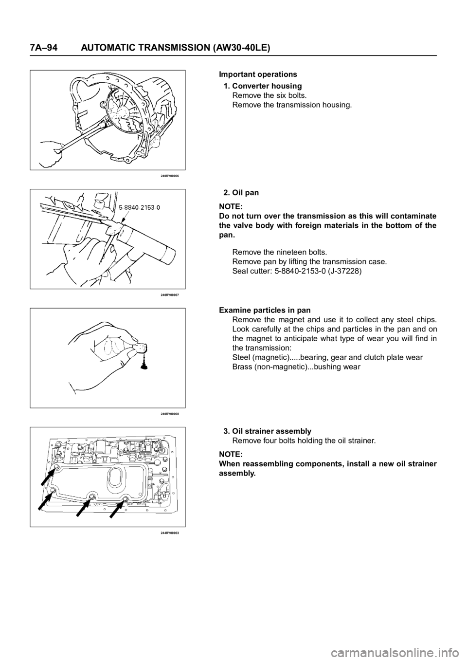
Important operations
1. Converter housing
Remove the six bolts.
Remove the transmission housing.
2. Oil pan
NOTE:
Do not turn over the transmission as this will contaminate
the valve body with foreign materials in the bottom of the
pan.
Remove the nineteen bolts.
Remove pan by lifting the transmission case.
Seal cutter: 5-8840-2153-0 (J-37228)
Examine particles in pan
Remove the magnet and use it to collect any steel chips.
Look carefully at the chips and par ticles in the pan and on
the magnet to anticipate what type of wear you will find in
the transmission:
Steel (magnetic).....bearing, gear and clutch plate wear
Brass (non-magnetic)...bushing wear
3. Oil strainer assembly
Remove four bolts holding the oil strainer.
NOTE:
When reassembling components, install a new oil strainer
assembly.