1998 OPEL FRONTERA ignition
[x] Cancel search: ignitionPage 1223 of 6000
6E–106
ENGINE DRIVEABILITY AND EMISSIONS
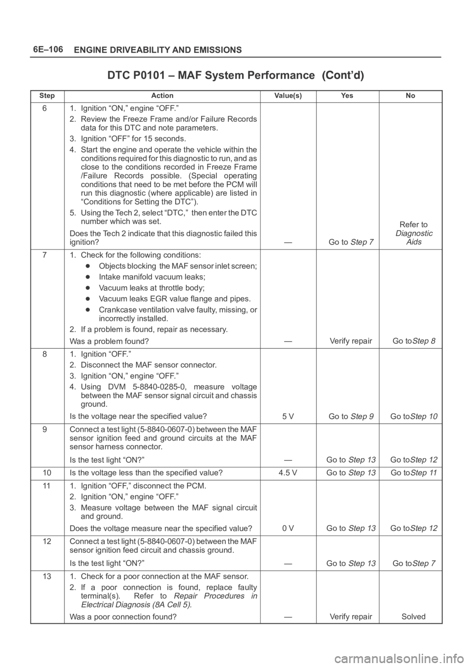
DTC P0101 – MAF System Performance
StepNo Ye s Va l u e ( s ) Action
61. Ignition “ON,” engine “OFF.”
2. Review the Freeze Frame and/or Failure Records
data for this DTC and note parameters.
3. Ignition “OFF” for 15 seconds.
4. Start the engine and operate the vehicle within the
conditions required for this diagnostic to run, and as
close to the conditions recorded in Freeze Frame
/Failure Records possible. (Special operating
conditions that need to be met before the PCM will
run this diagnostic (where applicable) are listed in
“Conditions for Setting the DTC”).
5. Using the Tech 2, select “DTC,” then enter the DTC
number which was set.
Does the Tech 2 indicate that this diagnostic failed this
ignition?
—Go to Step 7
Refer to
Diagnostic
Aids
71. Check for the following conditions:
Objects blocking the MAF sensor inlet screen;
Intake manifold vacuum leaks;
Vacuum leaks at throttle body;
Vacuum leaks EGR value flange and pipes.
Crankcase ventilation valve faulty, missing, or
incorrectly installed.
2. If a problem is found, repair as necessary.
Was a problem found?
—Verify repairGo toStep 8
81. Ignition “OFF.”
2. Disconnect the MAF sensor connector.
3. Ignition “ON,” engine “OFF.”
4. Using DVM 5-8840-0285-0, measure voltage
between the MAF sensor signal circuit and chassis
ground.
Is the voltage near the specified value?
5 VGo to Step 9Go toStep 10
9Connect a test light (5-8840-0607-0) between the MAF
sensor ignition feed and ground circuits at the MAF
sensor harness connector.
Is the test light “ON?”
—Go to Step 13Go toStep 12
10Is the voltage less than the specified value?4.5 VGo to Step 13Go toStep 11
111. Ignition “OFF,” disconnect the PCM.
2. Ignition “ON,” engine “OFF.”
3. Measure voltage between the MAF signal circuit
and ground.
Does the voltage measure near the specified value?
0 VGo to Step 13Go toStep 12
12Connect a test light (5-8840-0607-0) between the MAF
sensor ignition feed circuit and chassis ground.
Is the test light “ON?”
—Go to Step 13Go toStep 7
131. Check for a poor connection at the MAF sensor.
2. If a poor connection is found, replace faulty
terminal(s). Refer to
Repair Procedures in
Electrical Diagnosis (8A Cell 5).
Was a poor connection found?—Verify repairSolved
Page 1225 of 6000
6E–108
ENGINE DRIVEABILITY AND EMISSIONS
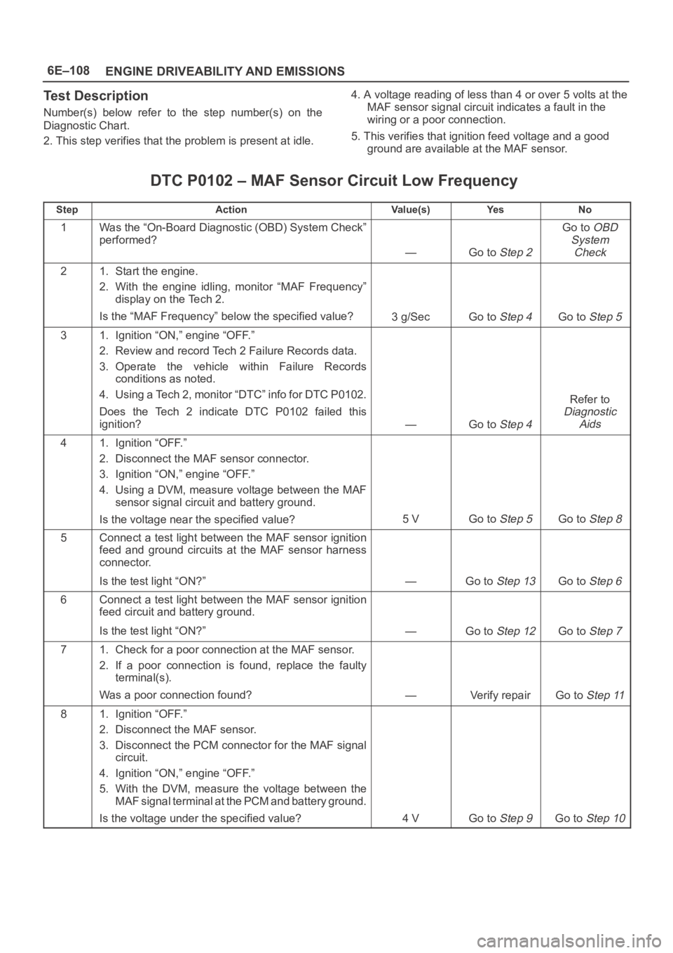
Test Description
Number(s) below refer to the step number(s) on the
Diagnostic Chart.
2. This step verifies that the problem is present at idle.4. A voltage reading of less than 4 or over 5 volts at the
MAF sensor signal circuit indicates a fault in the
wiring or a poor connection.
5. This verifies that ignition feed voltage and a good
ground are available at the MAF sensor.
DTC P0102 – MAF Sensor Circuit Low Frequency
StepActionVa l u e ( s )Ye sNo
1Was the “On-Board Diagnostic (OBD) System Check”
performed?
—Go to Step 2
Go to OBD
System
Check
21. Start the engine.
2. With the engine idling, monitor “MAF Frequency”
display on the Tech 2.
Is the “MAF Frequency” below the specified value?
3g/SecGo to Step 4Go to Step 5
31. Ignition “ON,” engine “OFF.”
2. Review and record Tech 2 Failure Records data.
3. Operate the vehicle within Failure Records
conditions as noted.
4. Using a Tech 2, monitor “DTC” info for DTC P0102.
Does the Tech 2 indicate DTC P0102 failed this
ignition?
—Go to Step 4
Refer to
Diagnostic
Aids
41. Ignition “OFF.”
2. Disconnect the MAF sensor connector.
3. Ignition “ON,” engine “OFF.”
4. Using a DVM, measure voltage between the MAF
sensor signal circuit and battery ground.
Is the voltage near the specified value?
5 VGo to Step 5Go to Step 8
5Connect a test light between the MAF sensor ignition
feed and ground circuits at the MAF sensor harness
connector.
Is the test light “ON?”
—Go to Step 13Go to Step 6
6Connect a test light between the MAF sensor ignition
feed circuit and battery ground.
Is the test light “ON?”
—Go to Step 12Go to Step 7
71. Check for a poor connection at the MAF sensor.
2. If a poor connection is found, replace the faulty
terminal(s).
Was a poor connection found?
—Verify repairGo to Step 11
81. Ignition “OFF.”
2. Disconnect the MAF sensor.
3. Disconnect the PCM connector for the MAF signal
circuit.
4. Ignition “ON,” engine “OFF.”
5. With the DVM, measure the voltage between the
MAF signal terminal at the PCM and battery ground.
Is the voltage under the specified value?
4 VGo to Step 9Go to Step 10
Page 1226 of 6000
6E–109 ENGINE DRIVEABILITY AND EMISSIONS
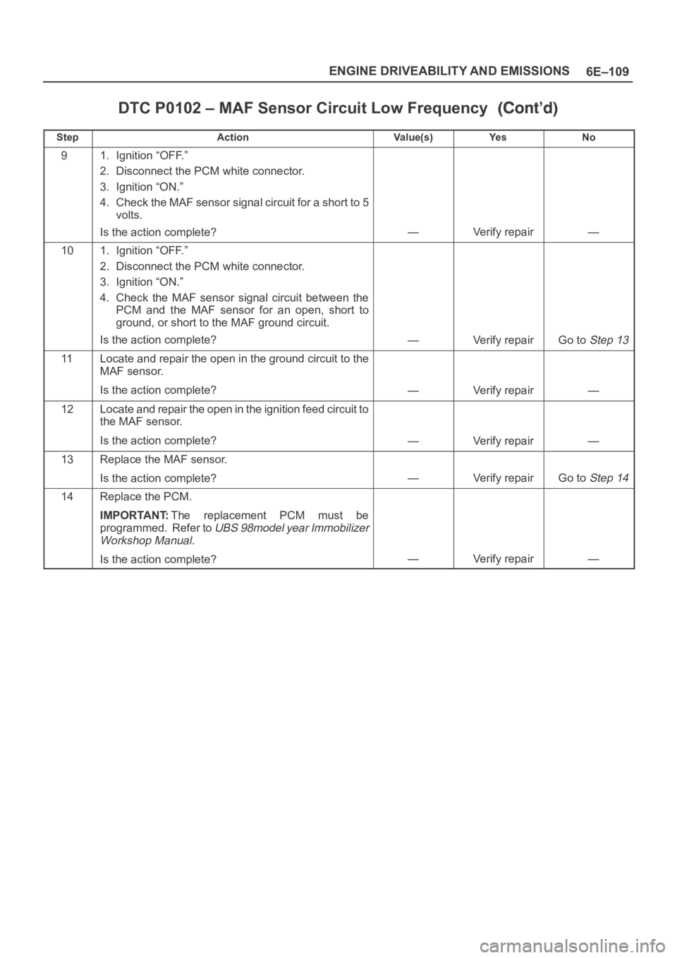
DTC P0102 – MAF Sensor Circuit Low Frequency
StepNo Ye s Va l u e ( s ) Action
91. Ignition “OFF.”
2. Disconnect the PCM white connector.
3. Ignition “ON.”
4. Check the MAF sensor signal circuit for a short to 5
volts.
Is the action complete?
—Verify repair—
101. Ignition “OFF.”
2. Disconnect the PCM white connector.
3. Ignition “ON.”
4. Check the MAF sensor signal circuit between the
PCM and the MAF sensor for an open, short to
ground, or short to the MAF ground circuit.
Is the action complete?
—Verify repairGo to Step 13
11Locate and repair the open in the ground circuit to the
MAF sensor.
Is the action complete?
—Verify repair—
12Locate and repair the open in the ignition feed circuit to
the MAF sensor.
Is the action complete?
—Verify repair—
13Replace the MAF sensor.
Is the action complete?
—Verify repairGo to Step 14
14Replace the PCM.
IMPORTANT:The replacement PCM must be
programmed. Refer to
UBS 98model year Immobilizer
Workshop Manual.
Is the action complete?—Verify repair—
Page 1228 of 6000
6E–111 ENGINE DRIVEABILITY AND EMISSIONS
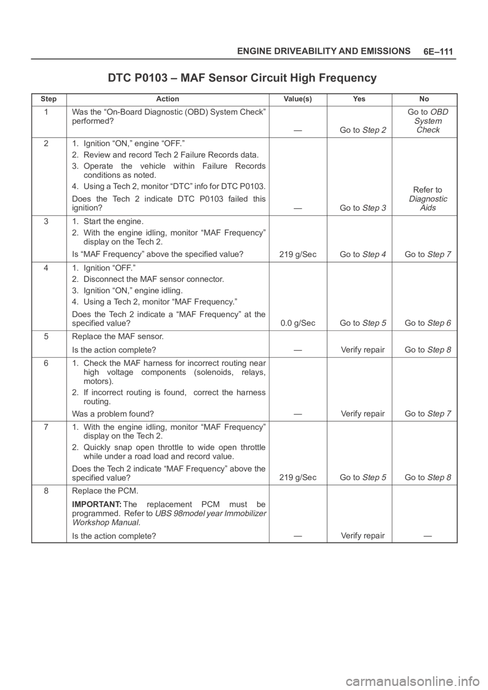
DTC P0103 – MAF Sensor Circuit High Frequency
StepActionVa l u e ( s )Ye sNo
1Was the “On-Board Diagnostic (OBD) System Check”
performed?
—Go to Step 2
Go to OBD
System
Check
21. Ignition “ON,” engine “OFF.”
2. Review and record Tech 2 Failure Records data.
3. Operate the vehicle within Failure Records
conditions as noted.
4. Using a Tech 2, monitor “DTC” info for DTC P0103.
Does the Tech 2 indicate DTC P0103 failed this
ignition?
—Go to Step 3
Refer to
Diagnostic
Aids
31. Start the engine.
2. With the engine idling, monitor “MAF Frequency”
display on the Tech 2.
Is “MAF Frequency” above the specified value?
219 g/SecGo to Step 4Go to Step 7
41. Ignition “OFF.”
2. Disconnect the MAF sensor connector.
3. Ignition “ON,” engine idling.
4. Using a Tech 2, monitor “MAF Frequency.”
Does the Tech 2 indicate a “MAF Frequency” at the
specified value?
0.0 g/SecGo to Step 5Go to Step 6
5Replace the MAF sensor.
Is the action complete?
—Verify repairGo to Step 8
61. Check the MAF harness for incorrect routing near
high voltage components (solenoids, relays,
motors).
2. If incorrect routing is found, correct the harness
routing.
Was a problem found?
—Verify repairGo to Step 7
71. With the engine idling, monitor “MAF Frequency”
display on the Tech 2.
2. Quickly snap open throttle to wide open throttle
while under a road load and record value.
Does the Tech 2 indicate “MAF Frequency” above the
specified value?
219 g/SecGo to Step 5Go to Step 8
8Replace the PCM.
IMPORTANT:The replacement PCM must be
programmed. Refer to
UBS 98model year Immobilizer
Workshop Manual.
Is the action complete?—Verify repair—
Page 1229 of 6000
6E–112
ENGINE DRIVEABILITY AND EMISSIONS
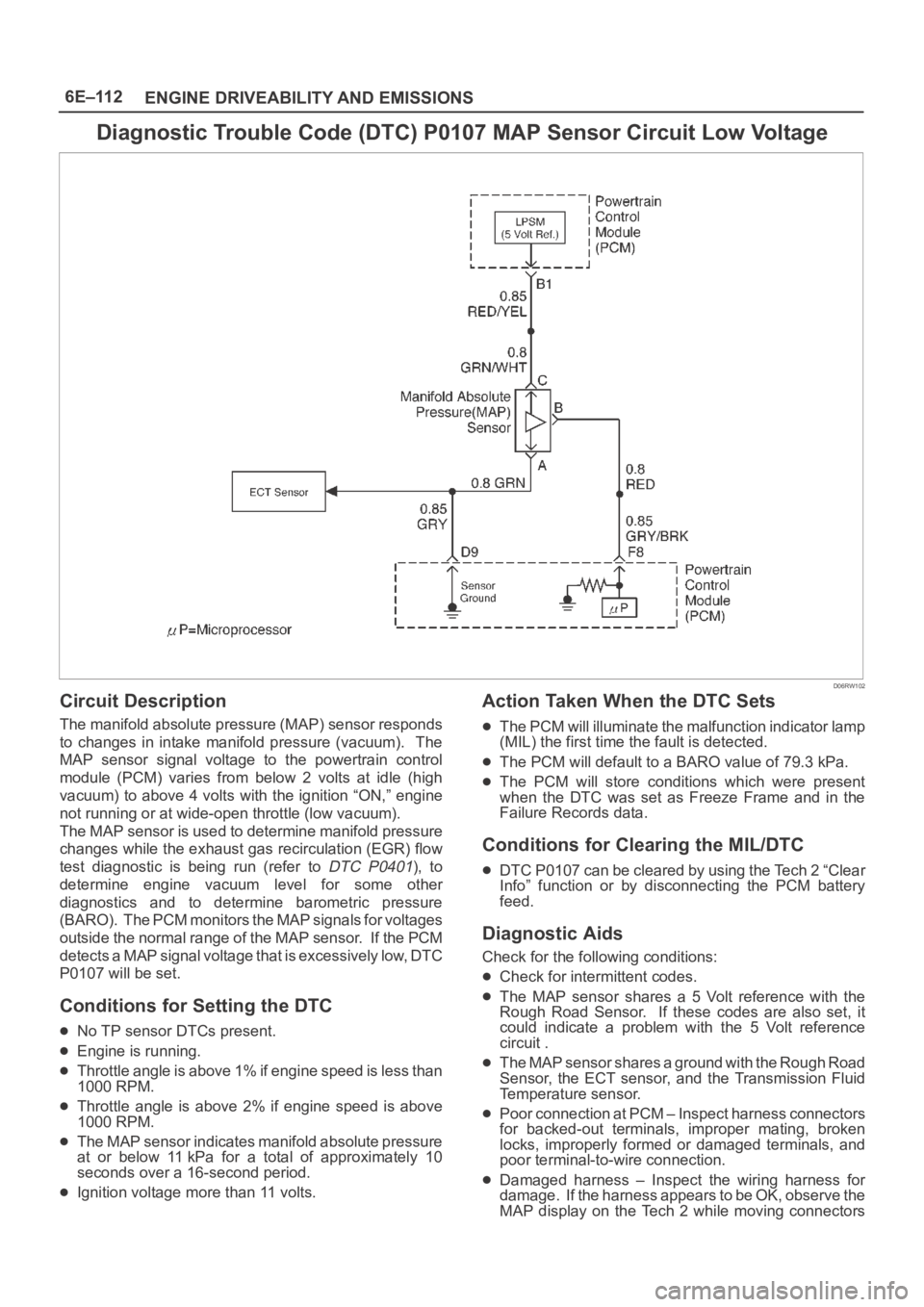
Diagnostic Trouble Code (DTC) P0107 MAP Sensor Circuit Low Voltage
D06RW102
Circuit Description
The manifold absolute pressure (MAP) sensor responds
to changes in intake manifold pressure (vacuum). The
MAP sensor signal voltage to the powertrain control
module (PCM) varies from below 2 volts at idle (high
vacuum) to above 4 volts with the ignition “ON,” engine
not running or at wide-open throttle (low vacuum).
The MAP sensor is used to determine manifold pressure
changes while the exhaust gas recirculation (EGR) flow
test diagnostic is being run (refer to
DTC P0401), to
determine engine vacuum level for some other
diagnostics and to determine barometric pressure
(BARO). The PCM monitors the MAP signals for voltages
outside the normal range of the MAP sensor. If the PCM
detects a MAP signal voltage that is excessively low, DTC
P0107 will be set.
Conditions for Setting the DTC
No TP sensor DTCs present.
Engine is running.
Throttle angle is above 1% if engine speed is less than
1000 RPM.
Throttle angle is above 2% if engine speed is above
1000 RPM.
The MAP sensor indicates manifold absolute pressure
at or below 11 kPa for a total of approximately 10
seconds over a 16-second period.
Ignition voltage more than 11 volts.
Action Taken When the DTC Sets
The PCM will illuminate the malfunction indicator lamp
(MIL) the first time the fault is detected.
The PCM will default to a BARO value of 79.3 kPa.
The PCM will store conditions which were present
when the DTC was set as Freeze Frame and in the
Failure Records data.
Conditions for Clearing the MIL/DTC
DTC P0107 can be cleared by using the Tech 2 “Clear
Info” function or by disconnecting the PCM battery
feed.
Diagnostic Aids
Check for the following conditions:
Check for intermittent codes.
The MAP sensor shares a 5 Volt reference with the
Rough Road Sensor. If these codes are also set, it
could indicate a problem with the 5 Volt reference
circuit .
The MAP sensor shares a ground with the Rough Road
Sensor, the ECT sensor, and the Transmission Fluid
Temperature sensor.
Poor connection at PCM – Inspect harness connectors
for backed-out terminals, improper mating, broken
locks, improperly formed or damaged terminals, and
poor terminal-to-wire connection.
Damaged harness – Inspect the wiring harness for
damage. If the harness appears to be OK, observe the
MAP display on the Tech 2 while moving connectors
Page 1230 of 6000
6E–113 ENGINE DRIVEABILITY AND EMISSIONS
and wiring harnesses related to the sensor. A change
in the display will indicate the location of the fault.
If DTC P0107 cannot be duplicated, the information
included in the Failure Records data can be useful indetermining vehicle mileage since the DTC was last set.
If it is determined that the DTC occurs intermittently,
performing the DTC P0107 Diagnostic Chart may isolate
the cause of the fault.
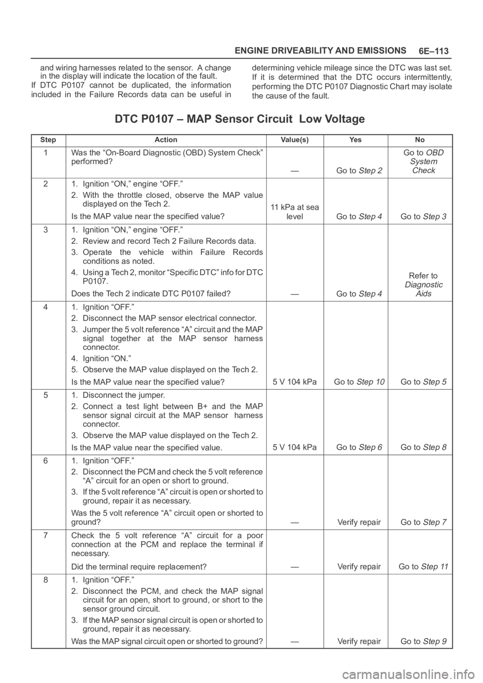
DTC P0107 – MAP Sensor Circuit Low Voltage
StepActionVa l u e ( s )Ye sNo
1Was the “On-Board Diagnostic (OBD) System Check”
performed?
—Go to Step 2
Go to OBD
System
Check
21. Ignition “ON,” engine “OFF.”
2. With the throttle closed, observe the MAP value
displayed on the Tech 2.
Is the MAP value near the specified value?
11 kPa at sea
level
Go to Step 4Go to Step 3
31. Ignition “ON,” engine “OFF.”
2. Review and record Tech 2 Failure Records data.
3. Operate the vehicle within Failure Records
conditions as noted.
4. Using a Tech 2, monitor “Specific DTC” info for DTC
P0107.
Does the Tech 2 indicate DTC P0107 failed?
—Go to Step 4
Refer to
Diagnostic
Aids
41. Ignition “OFF.”
2. Disconnect the MAP sensor electrical connector.
3. Jumper the 5 volt reference “A” circuit and the MAP
signal together at the MAP sensor harness
connector.
4. Ignition “ON.”
5. Observe the MAP value displayed on the Tech 2.
Is the MAP value near the specified value?
5 V 104 kPaGo to Step 10Go to Step 5
51. Disconnect the jumper.
2. Connect a test light between B+ and the MAP
sensor signal circuit at the MAP sensor harness
connector.
3. Observe the MAP value displayed on the Tech 2.
Is the MAP value near the specified value.
5 V 104 kPaGo to Step 6Go to Step 8
61. Ignition “OFF.”
2. Disconnect the PCM and check the 5 volt reference
“A” circuit for an open or short to ground.
3. If the 5 volt reference “A” circuit is open or shorted to
ground, repair it as necessary.
Was the 5 volt reference “A” circuit open or shorted to
ground?
—Verify repairGo to Step 7
7Check the 5 volt reference “A” circuit for a poor
connection at the PCM and replace the terminal if
necessary.
Did the terminal require replacement?
—Verify repairGo to Step 11
81. Ignition “OFF.”
2. Disconnect the PCM, and check the MAP signal
circuit for an open, short to ground, or short to the
sensor ground circuit.
3. If the MAP sensor signal circuit is open or shorted to
ground, repair it as necessary.
Was the MAP signal circuit open or shorted to ground?
—Verify repairGo to Step 9
Page 1233 of 6000
6E–116
ENGINE DRIVEABILITY AND EMISSIONS
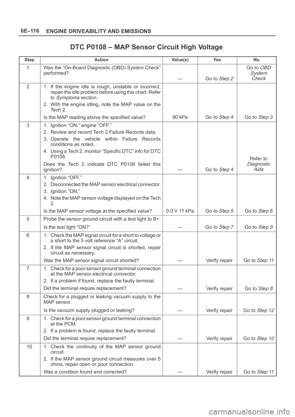
DTC P0108 – MAP Sensor Circuit High Voltage
StepActionVa l u e ( s )Ye sNo
1Was the “On-Board Diagnostic (OBD) System Check”
performed?
—Go to Step 2
Go to OBD
System
Check
21. If the engine idle is rough, unstable or incorrect,
repair the idle problem before using this chart. Refer
to
Symptoms section.
2. With the engine idling, note the MAP value on the
Te c h 2 .
Is the MAP reading above the specified value?
90 kPaGo to Step 4Go to Step 3
31. Ignition “ON,” engine “OFF.”
2. Review and record Tech 2 Failure Records data.
3. Operate the vehicle within Failure Records
conditions as noted.
4. Using a Tech 2, monitor “Specific DTC” info for DTC
P0108.
Does the Tech 2 indicate DTC P0108 failed this
ignition?
—Go to Step 4
Refer to
Diagnostic
Aids
41. Ignition “OFF.”
2. Disconnected the MAP sensor electrical connector.
3. Ignition “ON.”
4. Note the MAP sensor voltage displayed on the Tech
2.
Is the MAP sensor voltage at the specified value?
0.0 V 11 kPaGo to Step 5Go to Step 6
5Probe the sensor ground circuit with a test light to B+.
Is the test light “ON?”
—Go to Step 7Go to Step 9
61. Check the MAP signal circuit for a short to voltage or
a short to the 5 volt reference “A” circuit.
2. If the MAP sensor signal circuit is shorted, repair
circuit as necessary.
Was the MAP sensor signal circuit shorted?
—Verify repairGo to Step 11
71. Check for a poor sensor ground terminal connection
at the MAP sensor electrical connector.
2. If a problem if found, replace the faulty terminal.
Did the terminal require replacement?
—Verify repairGo to Step 8
8Check for a plugged or leaking vacuum supply to the
MAP sensor.
Is the vacuum supply plugged or leaking?
—Verify repairGo to Step 12
91. Check for a poor sensor ground terminal connection
at the PCM.
2. If a problem is found, replace the faulty terminal.
Did the terminal require replacement?
—Verify repairGo to Step 10
101. Check the continuity of the MAP sensor ground
circuit.
2. If the MAP sensor ground circuit measures over 5
ohms, repair open or poor connection.
Was a condition found and corrected?
—Verify repairGo to Step 11
Page 1237 of 6000
6E–120
ENGINE DRIVEABILITY AND EMISSIONS
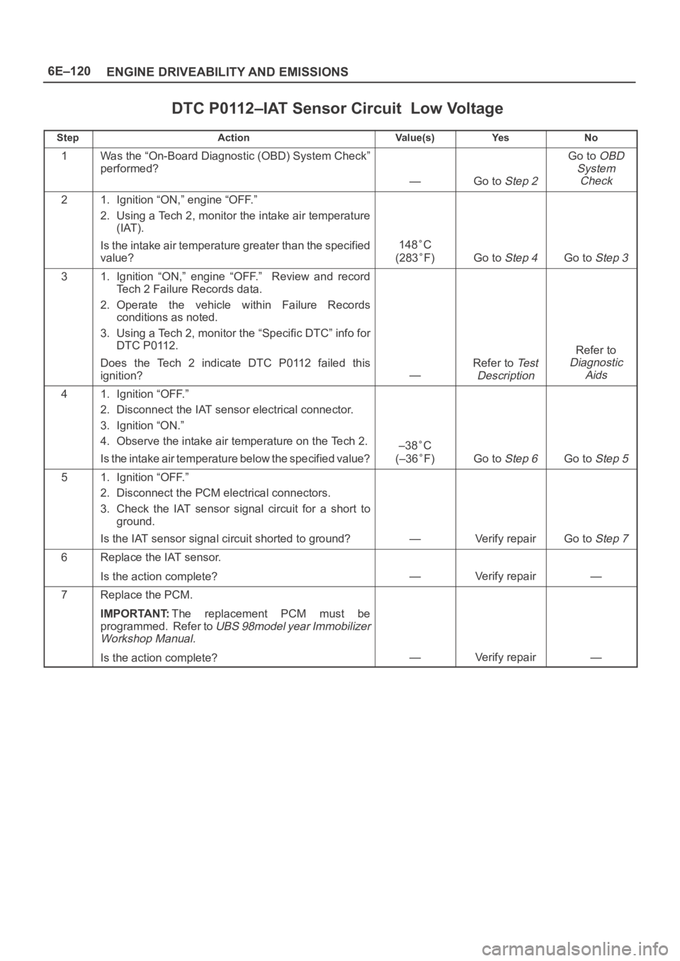
DTC P0112–IAT Sensor Circuit Low Voltage
StepActionVa l u e ( s )Ye sNo
1Was the “On-Board Diagnostic (OBD) System Check”
performed?
—Go to Step 2
Go to OBD
System
Check
21. Ignition “ON,” engine “OFF.”
2. Using a Tech 2, monitor the intake air temperature
(IAT).
Is the intake air temperature greater than the specified
value?
148C
(283
F)Go to Step 4Go to Step 3
31. Ignition “ON,” engine “OFF.” Review and record
Tech 2 Failure Records data.
2. Operate the vehicle within Failure Records
conditions as noted.
3. Using a Tech 2, monitor the “Specific DTC” info for
DTC P0112.
Does the Tech 2 indicate DTC P0112 failed this
ignition?
—
Refer to Te s t
Description
Refer to
Diagnostic
Aids
41. Ignition “OFF.”
2. Disconnect the IAT sensor electrical connector.
3. Ignition “ON.”
4. Observe the intake air temperature on the Tech 2.
Is the intake air temperature below the specified value?
–38C
(–36
F)Go to Step 6Go to Step 5
51. Ignition “OFF.”
2. Disconnect the PCM electrical connectors.
3. Check the IAT sensor signal circuit for a short to
ground.
Is the IAT sensor signal circuit shorted to ground?
—Verify repairGo to Step 7
6Replace the IAT sensor.
Is the action complete?
—Verify repair—
7Replace the PCM.
IMPORTANT:The replacement PCM must be
programmed. Refer to
UBS 98model year Immobilizer
Workshop Manual.
Is the action complete?—Verify repair—