1998 OPEL FRONTERA sensor
[x] Cancel search: sensorPage 821 of 6000

5A–11 BRAKE CONTROL SYSTEM
Data List
DisplayContentOK/NG Criteria for Data
Battery VoltageVo l t a g eBetween 10-16.9V
Brake Light SwitchOpen/CloseOpen(0V) when pedal is released
Closed(12V) when pedal is depressed.
Front Left Wheel Speed
Front Right Wheel Speed
Rear Left Wheel Speed
Rear Right Wheel SpeedMPH(km/h)Start the vehicle and make sure of linear change in each
wheel speed.
Turn each wheel by hand and make sure that each
speed data change.
Wheel Sensor StatusOK/NGTo be OK usually
G-sensorLow/HighTo be Low usually
Transfer Monitor(TOD)2 Wheel Drive
4 Wheel DriveWhen 2WD: 2 Wheel Drive
When 4WD: 4 Wheel Drive
Off-Road Switch
(Transmission Input)
Active/InactiveWhen shift lever position is 1, 2 and R: Active (M/T)
(Transmission Input)When shift lever position is L and R: Active (A/T)
Valve RelayActive/InactiveTo be Active usually
ABS StateON/OFFTo be OFF usually
ABS RelayActive/InactiveTo be Active usually
Return Pump RelayActive/InactiveTo be Inactive usually
Front Left Isolation ValveActive/InactiveTo be Inactive usually
Front Left Dump Valve
Front Right Isolation Valve
Front Right Dump Valve
Rear Isolation Valve
Rear Dump Valve
ABS Warning LampON/OFFTo be ON usually (while engine stopped)
Page 822 of 6000

5A–12
BRAKE CONTROL SYSTEM
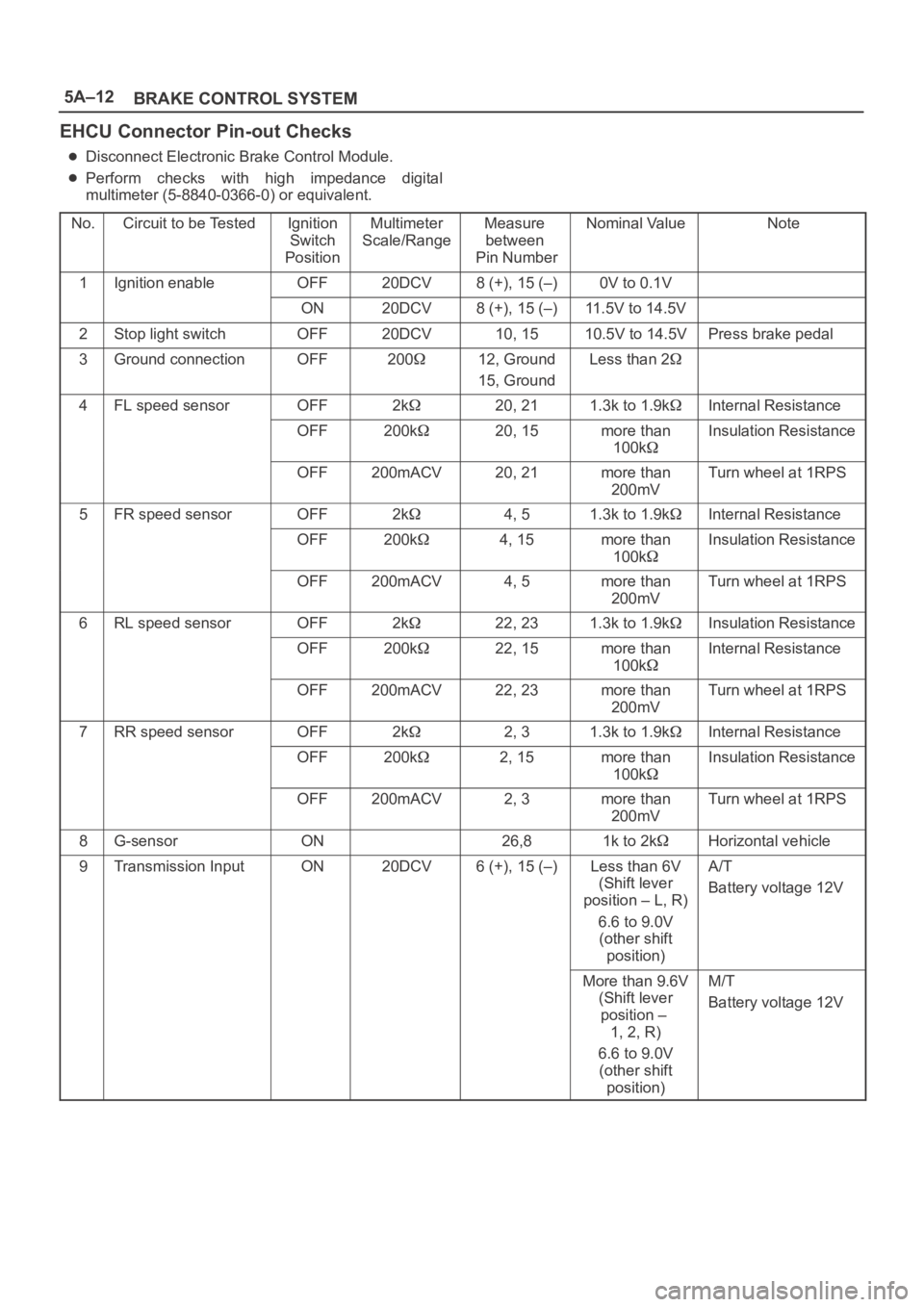
EHCU Connector Pin-out Checks
Disconnect Electronic Brake Control Module.
Perform checks with high impedance digital
multimeter (5-8840-0366-0) or equivalent.
No.
Circuit to be TestedIgnition
Switch
PositionMultimeter
Scale/RangeMeasure
between
Pin NumberNominal ValueNote
1Ignition enableOFF20DCV8 (+), 15 (–)0V to 0.1V
ON20DCV8 (+), 15 (–)11.5V to 14.5V
2Stop light switchOFF20DCV10, 1510.5V to 14.5VPress brake pedal
3Ground connectionOFF20012, Ground
15, GroundLess than 2
4FL speed sensorOFF2k20, 211.3k to 1.9kInternal Resistance
OFF200k20, 15more than
100kInsulation Resistance
OFF200mACV20, 21more than
200mVTurn wheel at 1RPS
5FR speed sensorOFF2k4, 51.3k to 1.9kInternal Resistance
OFF200k4, 15more than
100kInsulation Resistance
OFF200mACV4, 5more than
200mVTurn wheel at 1RPS
6RL speed sensorOFF2k22, 231.3k to 1.9kInsulation Resistance
OFF200k22, 15more than
100kInternal Resistance
OFF200mACV22, 23more than
200mVTurn wheel at 1RPS
7RR speed sensorOFF2k2, 31.3k to 1.9kInternal Resistance
OFF200k2, 15more than
100kInsulation Resistance
OFF200mACV2, 3more than
200mVTurn wheel at 1RPS
8G-sensorON26,81k to 2kHorizontal vehicle
9Transmission InputON20DCV6 (+), 15 (–)Less than 6V
(Shift lever
position – L, R)
6.6 to 9.0V
(other shift
position)A/T
Battery voltage 12V
More than 9.6V
(Shift lever
position –
1, 2, R)
6.6 to 9.0V
(other shift
position)M/T
Battery voltage 12V
Page 845 of 6000

5A–35 BRAKE CONTROL SYSTEM
Symptom Diagnosis
The symptoms that cannot be indicated by the warning
light can be divided in the following five categories:
1. ABS works frequently but vehicle does not
decelerate.
2. Uneven braking occurs while ABS works.
3. The wheels lock during braking.4. Brake pedal feel is abnormal.
5. Braking sound (from EHCU) is heard while not
braking.
These are all attributable to problems which cannot be de-
tected by EHCU self-diagnosis. Use the customer com-
plaint and a test to determine which symptom is present.
Then follow the appropriate flow chart listed below.
NoSymptomDiagnostic Flow ChartsNo.Sym tomWithout TECH 2With TECH 2
1ABS works frequently but vehicle does not decelerate.Chart A–1Chart TA–1
2Uneven braking occurs while ABS works.Chart A–2—
3The wheels are locked.Chart A–3Chart TA–3
4Brake pedal feel is abnormal.Chart A–4—
5Braking sound (from EHCU) is heard while not braking. Chart A–5Chart TA–5
Chart A–1 ABS Works Frequently But Vehicle Does Not Decelerate
StepActionYe sNo
11. Turn key off.
2. G Sensor connector and EHCU connector disconnected.
Is there continuity between EHCU terminals 26 and 8?
Go to Step 2Go to Step 3
2Connect EHCU connector.
Is there continuity between the G sensor and the EHCU?
Go to Step 3
Repair circuit.
Go to Step 1
3Is the G sensor normal? (Refer to chart B-5)
Go to Step 4
Replace G
sensor.
Go to Step 11
4Is braking force distribution normal between the front and rear of
the vehicle?
Go to Step 5
Repair brake
parts.
Go to Step 11
5Are axle parts installed normally?Go to Step 6Repair axle parts.
Go to Step 11
6Is there play in each wheel speed sensor?Repair wheel
speed sensor.
Go to Step 11
Go to Step 7
7Is there damage, or powered iron sticking to each wheel speed
sensor/sensor ring?Replace sensor
or sensor ring.
Go to Step 11
Go to Step 8
8Is the output of each wheel speed sensor normal? (Refer to chart
C-1 or TC-1)
Go to Step 9
Replace wheel
speed sensor or
repair harness.
Go to Step 11
9Is the input of transmission normal? (Refer to chart C-2 or TC-2)
Go to Step 10
Replace switch or
repair harness.
Go to Step 11
Page 846 of 6000

5A–36
BRAKE CONTROL SYSTEM
StepNo Ye s
Action
10Is the input of 4WD controller normal?
Go to Step 11
Replace
controller or
repair harness.
Go to Step 11
11Reconnect all components and ensure all components are
properly mounted.
Was this step finished?Repeat the “Basic
diagnostic flow
chart.”
Go to Step 11
Chart TA-1 ABS Works Frequently But Vehicle Does Not Decelerate (Use TECH 2)
StepActionYe sNo
11. Connect TECH 2.
2. Make sure of the output conditions of each wheel speed
sensor by mode “F1: Data Display”.
Is the output of each sensor normal?
Go to Step 2
Replace wheel
speed sensor.
Go to Step 3
2Return to Chart A-1.
Was the Chart A-1 finished?
Go to Step 3Go to Step 2
3Reconnect all components, ensure all components are properly
mounted.
Was this step finished?Repeat the “Basic
diagnostic flow
chart.”
Go to Step 3
Chart A-2 Uneven Braking Occurs While ABS Works
StepActionYe sNo
1Is there play in each sensor?Repair.
Go to Step 5
Go to Step 2
2Is there damage or powdered iron sticking to each sensor/sensor
ring?Repair.
Go to Step 5
Go to Step 3
3Is the output of each sensor normal? (Refer to chart C-1 or TC-1)
Go to Step 4
Replace sensor
or repair harness.
Go to Step 5
4Is brake pipe connecting order correct?
Replace EHCU.
Go to Step 5
Reconnect brake
pipe correctly.
Go to Step 5
5Reconnect all components, ensure all components are properly
mounted.
Was this step finished?Repeat the “Basic
diagnostic flow
chart.”
Go to Step 5
Chart A-3, TA-3 The Wheels Are Locked
StepActionYe sNo
1Is ABS working?Go to Step 2Go to Step 6
2Is vehicle speed under 10 km/h (6mph)?Normal.Go to Step 3
3Is sensor output normal? (Chart C-1 or TC-1)
Go to Step 4
Replace sensor
or repair harness.
Go to Step 9
4Is transmission input normal? (Chart C-2 or TC-2)
Go to Step 5
Replace SW or
repair harness.
Go to Step 9
Page 848 of 6000

5A–38
BRAKE CONTROL SYSTEM
Chart A-5, TA-5 Braking Sound (From EHCU) Is Heard While Not Braking
StepActionYe sNo
1Is this the first time the vehicle is being driven after starting the
engine?It is self checking
sound.
Normal.
Go to Step 2
2Is vehicle speed under 10 km/h (6 mph)?It is self checking
sound.
Normal.
Go to Step 3
3Check for the following condition:
At the time of shift down or clutch operation.
A t t h e t i m e o f l o w drive (ice or snow road) or rough road drive.
At the time of high-speed turn.
At the time of passing curb.
At the time of operating electrical equipment switches.
At the time of racing the engine (over 5000 rpm).
Did it occur under any one condition above?
ABS may
sometime be
actuated even
when brake pedal
is not applied.
Go to Step 4
4Is there play in each sensor/wheel speed sensor rings?
Go to Step 5
Repair.
Go to Step 7
5Damage or powdered iron sticking to each sensor/wheel speed
sensor ring?
Go to Step 6
Repair.
Go to Step 7
6Is each sensor output normal?(Refer to chart C-1 or TC-1).Check harness/
connector for
suspected
disconnection.
If no
disconnection is
found, replace
EHCU.
Go to Step 7
Repair.
Go to Step 7
7Reconnect all components, ensure all components are properly
mounted.
Was this step finished?Repeat the “Basic
diagnostic flow
chart.”
Go to Step 7
Page 849 of 6000

5A–39 BRAKE CONTROL SYSTEM
Diagnostic Trouble Codes
Choose and trace an appropriate flowchart by the
numbers listed below to find fault and repair.
Code
ItemDiagnosisChart No.
12Start CodeNormal—
14EHCU FunctionAbnormality in input/output, operational and
control circuitsB-2
15Power Voltage DropB-3
16CLASS–2 Communication Line Ab-
normalityB-4
21G-sensorWiring disconnectionB-5
23Transmission InputInput abnormalityB-6
24Transfer MonitorB-7
32Motor & Motor RelayShorted or disconnected coilB-8
35Valve RelayShorted or disconnected coil/wiringB-9
41FL Holding Solenoid ValveShorted or disconnected coil/wiringB-10
42FL Decompression Solenoid ValveShorted or disconnected coil/wiringB-11
43FR Holding Solenoid ValveShorted or disconnected coil/wiringB-12
44FR Decompression Solenoid ValveShorted or disconnected coil/wiringB-13
45Rear Holding Solenoid ValveShorted or disconnected coil/wiringB-14
46Rear Decompression Solenoid ValveShorted or disconnected coil/wiringB-15
51FL Wheel Speed SensorDisconnected coil/wiringB-16
52FR Wheel Speed SensorDisconnected coil/wiringB-17
53RL Wheel Speed SensorDisconnected coil/wiringB-18
54RR Wheel Speed SensorDisconnected coil/wiringB-19
61FL Wheel Speed SensorShorted coil/wiringB-20
62FR Wheel Speed SensorShorted coil/wiringB-21
63RL Wheel Speed SensorShorted coil/wiringB-22
64RR Wheel Speed SensorShorted coil/wiringB-23
65Sensor Signal InputWrong number of teethB-24
Page 855 of 6000

5A–45 BRAKE CONTROL SYSTEM
Chart B-5 G-Sensor Circuit (DTC 21)
StepActionYe sNo
1Vehicle placed horizontal.
Is the resistance between the G sensor connector terminals 1 and
2 within 4.0-6.0 k
?
Check harness
connector for
short.
Fault found :
Repair , and
perform system
self-check.
No fault found :
replace EHCU.
Go to Step 3
Go to Step 2
2Is the bracket installed horizontally?
Go to Step 4
Repair or replace
bracket.
Go to Step 4
3Remove G sensor.
Is the resistance between the G sensor connector terminals 1 and
2 within 1.0-2.0 k
when G sensor is horizontal?Go to Step 4
Replace G
sensor.
Go to Step 5
4Measure resistance between G sensor connector terminals 1 and
2 within 4.0-6.0 k
when G sensor tilted to 30 or more?
Harness between
EHCU and G
sensor is faulty
and short.
Repair the
harness
Go to Step 5
Replace G
sensor.
Go to Step 5
51. Reconnect all components and ensure all components are
properly mounted.
2. Clear diagnostic trouble code.
Was this step finished?
Repeat the “Basic
diagnostic flow
chart.”
Go to Step 5
Page 860 of 6000

5A–50
BRAKE CONTROL SYSTEM
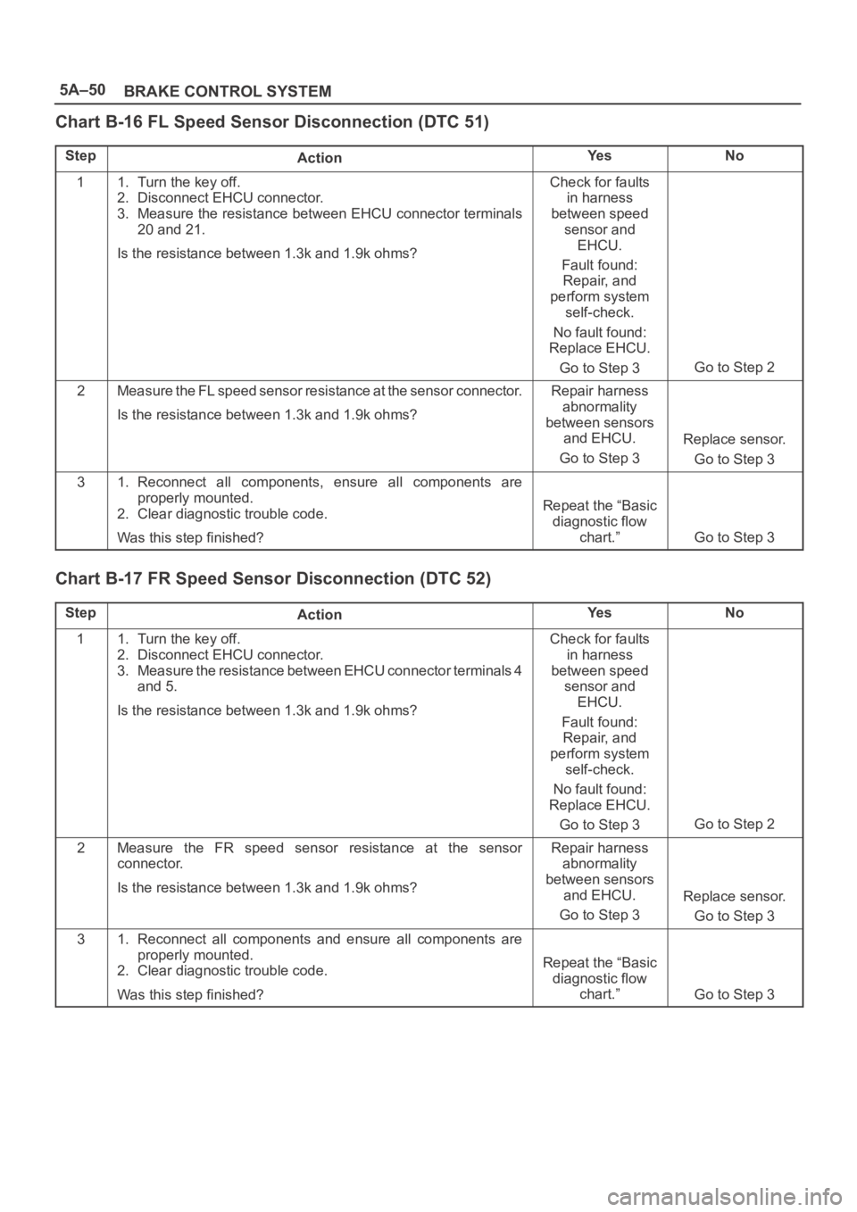
Chart B-16 FL Speed Sensor Disconnection (DTC 51)
StepActionYe sNo
11. Turn the key off.
2. Disconnect EHCU connector.
3. Measure the resistance between EHCU connector terminals
20 and 21.
Is the resistance between 1.3k and 1.9k ohms?Check for faults
in harness
between speed
sensor and
EHCU.
Fault found:
Repair, and
perform system
self-check.
No fault found:
Replace EHCU.
Go to Step 3
Go to Step 2
2Measure the FL speed sensor resistance at the sensor connector.
Is the resistance between 1.3k and 1.9k ohms?Repair harness
abnormality
between sensors
and EHCU.
Go to Step 3
Replace sensor.
Go to Step 3
31. Reconnect all components, ensure all components are
properly mounted.
2. Clear diagnostic trouble code.
Was this step finished?
Repeat the “Basic
diagnostic flow
chart.”
Go to Step 3
Chart B-17 FR Speed Sensor Disconnection (DTC 52)
StepActionYe sNo
11. Turn the key off.
2. Disconnect EHCU connector.
3. Measure the resistance between EHCU connector terminals 4
and 5.
Is the resistance between 1.3k and 1.9k ohms?Check for faults
in harness
between speed
sensor and
EHCU.
Fault found:
Repair, and
perform system
self-check.
No fault found:
Replace EHCU.
Go to Step 3
Go to Step 2
2Measure the FR speed sensor resistance at the sensor
connector.
Is the resistance between 1.3k and 1.9k ohms?Repair harness
abnormality
between sensors
and EHCU.
Go to Step 3
Replace sensor.
Go to Step 3
31. Reconnect all components and ensure all components are
properly mounted.
2. Clear diagnostic trouble code.
Was this step finished?
Repeat the “Basic
diagnostic flow
chart.”
Go to Step 3