1998 NISSAN PICK-UP service
[x] Cancel search: servicePage 101 of 1659
Service Notice
lWhen removing or installing various parts, place a cloth or padding onto the vehicle body to prevent
scratches.
lHandle trim, molding, instruments, grille, etc. carefully during removing or installing. Be careful not to soil
or damage them.
lApply sealing compound where necessary when installing parts.
lWhen applying sealing compound, be careful that the sealing compound does not protrude from parts.
lWhen replacing any metal parts (for example body outer panel, members, etc.), be sure to take rust
prevention measures.
Supplemental Restraint System (SRS) ``AIR
BAG'' (4WD models)
The Supplemental Restraint System ``AIR BAG'', used along with a seat belt, helps to reduce the risk or
severity of injury to the driver in a frontal collision. The Supplemental Restraint System consists of air bag
module (located in the center of the steering wheel), a diagnosis sensor unit, warning lamp, wiring harness
and spiral cable. Information necessary to service the system safely is included in theRS sectionof this
Service Manual.
WARNING:
lTo avoid rendering the SRS inoperative, which could increase the risk of personal injury or death
in the event of a collision which would result in air bag inflation, all maintenance must be per-
formed by an authorized NISSAN dealer.
lImproper maintenance, including incorrect removal and installation of the SRS, can lead to per-
sonal injury caused by unintentional activation of the system.
lDo not use electrical test equipment on any circuit related to the SRS unless instructed to in this
Service Manual. SRS wiring harnesses are covered with yellow insulation either just before the
harness connectors or for the complete harness, for easy identification.
Supplemental Restraint System (SRS) ``AIR
BAG'' (2WD models)
The Supplemental Restraint System ``AIR BAG'', used along with a seat belt, helps to reduce the risk or
severity of injury to the driver in a frontal collision. The Supplemental Restraint System consists of air bag
module (located in the center of the steering wheel), diagnosis sensor unit, warning lamp, wiring harness
and spiral cable. Information necessary to service the system safely is included in theRS sectionof this
Service Manual.
WARNING:
lTo avoid rendering the SRS inoperative, which could increase the risk of personal injury or death
in the event of a collision which would result in air bag inflation, all maintenance must be per-
formed by an authorized NISSAN dealer.
lImproper maintenance, including incorrect removal and installation of the SRS, can lead to per-
sonal injury caused by unintentional activation of the system.
lDo not use electrical test equipment on any circuit related to the SRS unless instructed to in this
Service Manual.
PRECAUTIONS
BT-1
Page 150 of 1659
ENGINE CONTROL SYSTEM
SECTION
EC
CONTENTS
DIAGNOSTIC TROUBLE CODE INDEX................... 1
Alphabetical & Numerical Index for DTC
(KA engine) ............................................................ 1
PRECAUTIONS AND PREPARATION..................... 2
Special Service Tools ............................................ 2
Commercial Service Tool....................................... 4
Supplemental Restraint System (SRS) ``AIR
BAG'' (4WD models).............................................. 4
Supplemental Restraint System (SRS) ``AIR
BAG'' (2WD models).............................................. 4
KA
PRECAUTIONS AND PREPARATION..................... 5
Engine Fuel & Emission Control System .............. 5
Precautions ............................................................ 6
ENGINE AND EMISSION CONTROL OVERALL
SYSTEM..................................................................... 8
Circuit Diagram ...................................................... 8
System Diagram .................................................... 9
ECCS Component Parts Location ....................... 10
Vacuum Hose Drawing ........................................ 12
System Chart ....................................................... 13
ENGINE AND EMISSION BASIC CONTROL
SYSTEM DESCRIPTION..................................... 14
Multiport Fuel Injection (MFI) System.................. 14
Distributor Ignition (DI) System............................ 17
Air Conditioning Cut Control ................................ 18
Fuel Cut Control (at no load & high engine
speed) .................................................................. 18
EVAPORATIVE EMISSION SYSTEM..................... 19
Description ........................................................... 19
Inspection ............................................................. 19POSITIVE CRANKCASE VENTILATION................ 21
Description ........................................................... 21
Inspection ............................................................. 21
BASIC SERVICE PROCEDURE............................. 22
Fuel Pressure Release ........................................ 22
Fuel Pressure Check ........................................... 22
Injector Removal and Installation ........................ 23
Fast Idle Cam (FIC) Inspection and
Adjustment ........................................................... 24
Idle Speed/Ignition Timing/Idle Mixture Ratio
Adjustment ........................................................... 25
ON BOARD DIAGNOSTIC SYSTEM
DESCRIPTION......................................................... 36
Introduction .......................................................... 36
Diagnostic Trouble Code (DTC) .......................... 36
Malfunction Indicator Lamp (MIL) ........................ 38
CONSULT ............................................................ 45
TROUBLE DIAGNOSIS - Introduction.................. 54
Introduction .......................................................... 54
Diagnostic Worksheet .......................................... 54
TROUBLE DIAGNOSIS - Work Flow..................... 56
Work Flow ............................................................ 56
Description for Work Flow ................................... 57
TROUBLE DIAGNOSIS - Basic Inspection.......... 58
Basic Inspection ................................................... 58
TROUBLE DIAGNOSIS - General Description..... 61
Fail-Safe Chart ..................................................... 61
Symptom Matrix Chart ......................................... 62
CONSULT Reference Value in Data Monitor
Mode .................................................................... 64
Major Sensor Reference Graph in Data
Monitor Mode ....................................................... 66
ECM Terminals and Reference Value ................. 68
EC
Page 151 of 1659

TROUBLE DIAGNOSIS FOR POWER SUPPLY.... 75
Main Power Supply and Ground Circuit .............. 75
TROUBLE DIAGNOSIS FOR ``CAMSHAFT
POSI SEN'' (DTC 11).............................................. 82
Camshaft Position Sensor (CMPS) ..................... 82
TROUBLE DIAGNOSIS FOR ``MASS AIR
FLOW SEN'' (DTC 12)............................................ 89
Mass Air Flow Sensor (MAFS) ............................ 89
TROUBLE DIAGNOSIS FOR ``COOLANT TEMP
SEN'' (DTC 13)........................................................ 95
Engine Coolant Temperature Sensor (ECTS) ..... 95
TROUBLE DIAGNOSIS FOR ``IGN SIGNAL-
PRIMARY'' (DTC 21)............................................... 99
Ignition Signal ...................................................... 99
TROUBLE DIAGNOSIS FOR ``OVER HEAT''
(DTC 28)................................................................. 106
Overheat ............................................................ 106
TROUBLE DIAGNOSIS FOR ``INT AIR TEMP
SEN'' (DTC 41)...................................................... 109
Intake Air Temperature Sensor ......................... 109
TROUBLE DIAGNOSIS FOR ``THROTTLE POSI
SEN'' (DTC 43)...................................................... 113
Throttle Position Sensor .................................... 113
TROUBLE DIAGNOSIS FOR
NON-DETECTABLE ITEMS.................................. 118
Vehicle Speed Sensor (VSS) ............................ 118
Heated Oxygen Sensor (HO2S)
- LHD Models - .................................................. 123
Heated Oxygen Sensor Heater
- LHD Models - .................................................. 127
Idle Air Control Valve (IACV) - Auxiliary Air
Control (AAC) Valve .......................................... 131
Neutral Position Switch ...................................... 136
EVAP Canister Purge Control Solenoid Valve .. 140
Injector ............................................................... 144
Start Signal ........................................................ 149
Fuel Pump.......................................................... 151
Power Steering Oil Pressure Switch ................. 157
Swirl Control Valve Control Solenoid Valve ...... 161
IACV-FICD Solenoid Valve ................................ 168
MIL & Data Link Connectors ............................. 173
TD
INJECTION SYSTEM............................................ 176
Fuel System ....................................................... 176
INJECTION PUMP................................................. 178
Inspection ........................................................... 178
Removal ............................................................. 178
Installation and Adjustment................................ 180
Disassembly ....................................................... 183
Load Timer Adjustment...................................... 183
Start Q Adjustment Lever .................................. 184
INJECTION NOZZLE............................................. 186Removal and Installation ................................... 186
Disassembly ....................................................... 186
Inspection ........................................................... 187
Cleaning ............................................................. 187
Assembly............................................................ 189
Test and Adjustment .......................................... 189
FUEL SYSTEM CHECK........................................ 191
Bleeding Fuel System ........................................ 191
Bleeding Fuel Filter ............................................ 192
Checking Priming Pump .................................... 192
Checking Fuel Filter Switch ............................... 192
POSITIVE CRANKCASE VENTILATION.............. 193
Description ......................................................... 193
Inspection ........................................................... 193
QUICK-GLOW SYSTEM........................................ 194
Component Parts Location ................................ 194
Circuit Diagram .................................................. 195
Description ......................................................... 196
Wiring Diagram .................................................. 197
Glow Control Unit Circuit Inspection (For Cold
Areas)................................................................. 203
Glow Control Unit Circuit Inspection (Except
for Cold Areas)................................................... 206
Component Inspection ....................................... 208
EGR SYSTEM........................................................ 210
Component Parts Location ................................ 210
Description ......................................................... 211
Operation ........................................................... 212
Wiring Diagram .................................................. 213
System Inspection.............................................. 217
Component Inspection ....................................... 218
SOLENOID TIMER................................................ 220
Description ......................................................... 220
Operation ........................................................... 220
Wiring Diagram .................................................. 222
Inspection ........................................................... 224
FUEL CUT SYSTEM.............................................. 225
Wiring Diagram .................................................. 225
FUEL HEATER SYSTEM...................................... 226
Description ......................................................... 226
Wiring Diagram .................................................. 227
System Inspection.............................................. 228
Component Inspection ....................................... 228
FAST IDLE CONTROL CIRCUIT.......................... 230
Wiring Diagram .................................................. 230
Electrical Components Inspection ..................... 231
KA
SERVICE DATA AND SPECIFICATIONS (SDS). 232
General Specifications ....................................... 232
Inspection and Adjustment ................................ 232
Page 152 of 1659
TD
SERVICE DATA AND SPECIFICATIONS (SDS). 233
VE-type Injection Pump ..................................... 233Injection Nozzle.................................................. 233
Injection Pump Calibration Standard ................. 234
When you read wiring diagrams:
lRead GI section, ``HOW TO READ WIRING DIAGRAMS''.
lSee EL section, ``POWER SUPPLY ROUTING'' for power distribution circuit.
When you perform trouble diagnoses, read GI section, ``HOW TO FOLLOW FLOW
CHART IN TROUBLE DIAGNOSES'' and ``HOW TO PERFORM EFFICIENT DIAGNOSIS
FOR AN ELECTRICAL INCIDENT''.
Page 154 of 1659
Special Service Tools
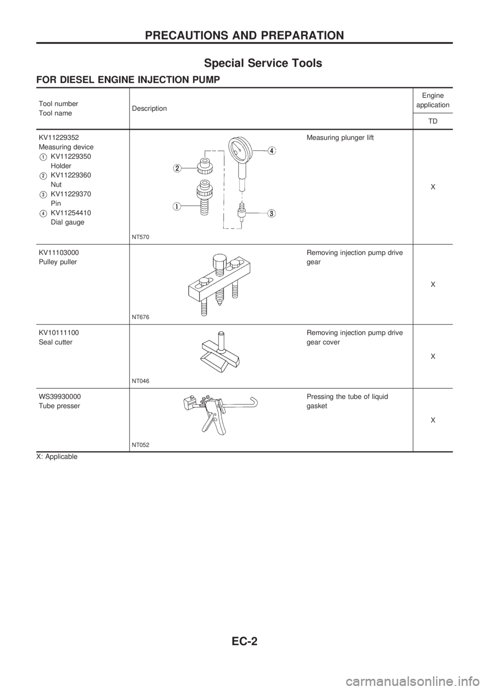
FOR DIESEL ENGINE INJECTION PUMP
Tool number
Tool nameDescriptionEngine
application
TD
KV11229352
Measuring device
V1KV11229350
Holder
V2KV11229360
Nut
V3KV11229370
Pin
V4KV11254410
Dial gauge
NT570
Measuring plunger lift
X
KV11103000
Pulley puller
NT676
Removing injection pump drive
gear
X
KV10111100
Seal cutter
NT046
Removing injection pump drive
gear cover
X
WS39930000
Tube presser
NT052
Pressing the tube of liquid
gasket
X
X: Applicable
PRECAUTIONS AND PREPARATION
EC-2
Page 155 of 1659
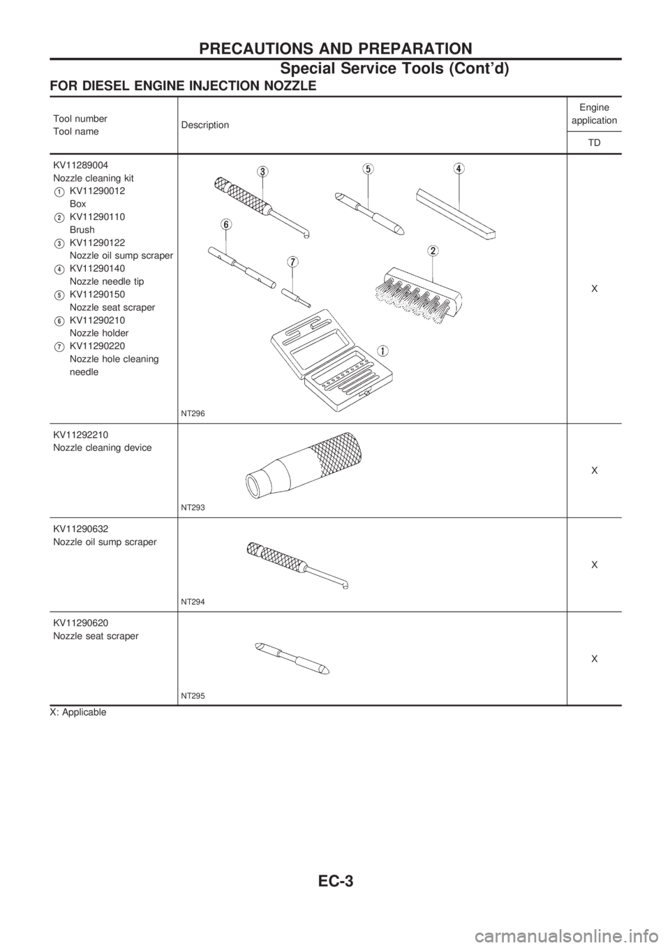
FOR DIESEL ENGINE INJECTION NOZZLE
Tool number
Tool nameDescriptionEngine
application
TD
KV11289004
Nozzle cleaning kit
V1KV11290012
Box
V2KV11290110
Brush
V3KV11290122
Nozzle oil sump scraper
V4KV11290140
Nozzle needle tip
V5KV11290150
Nozzle seat scraper
V6KV11290210
Nozzle holder
V7KV11290220
Nozzle hole cleaning
needle
NT296
X
KV11292210
Nozzle cleaning device
NT293
X
KV11290632
Nozzle oil sump scraper
NT294
X
KV11290620
Nozzle seat scraper
NT295
X
X: Applicable
PRECAUTIONS AND PREPARATION
Special Service Tools (Cont'd)
EC-3
Page 156 of 1659
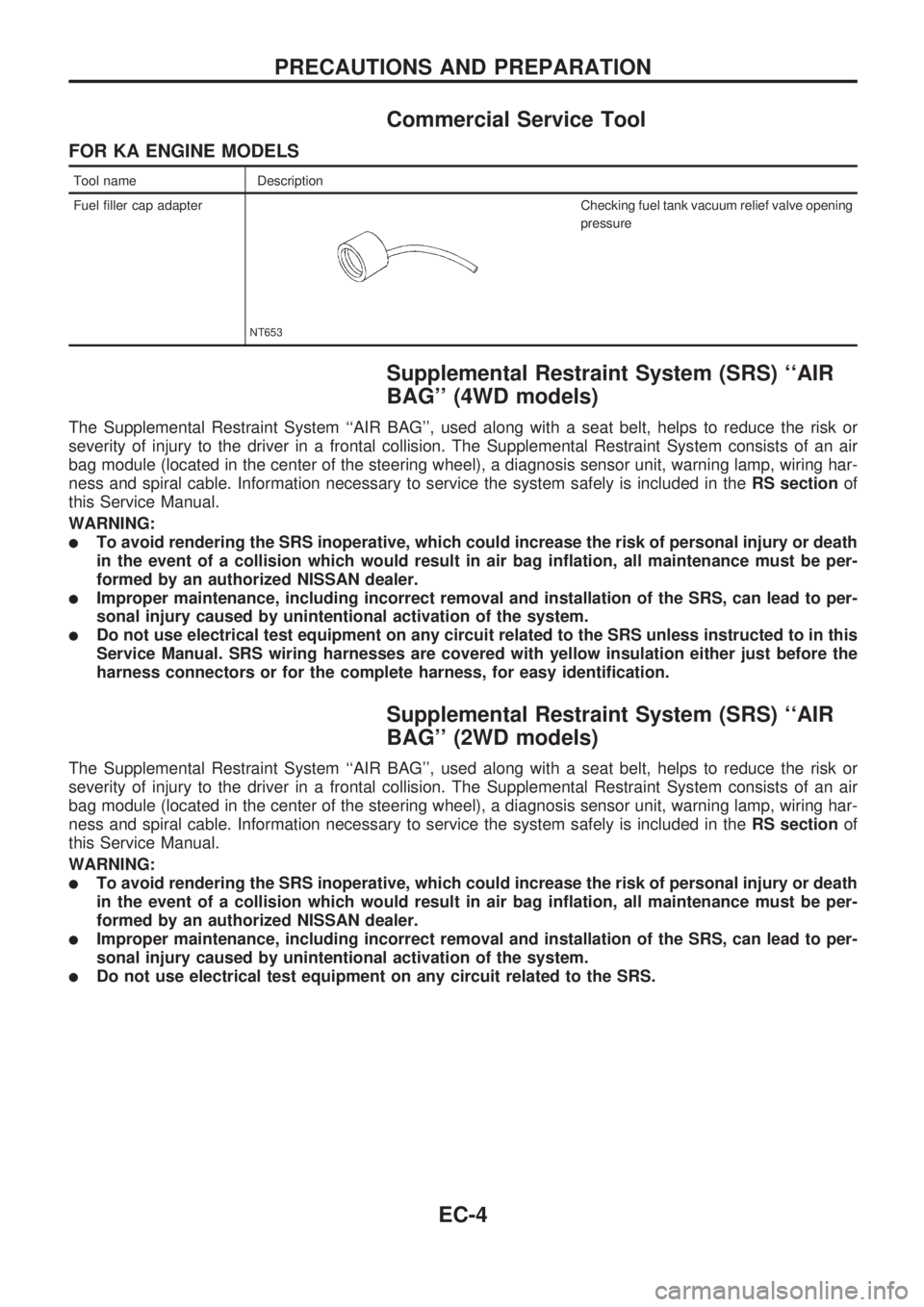
Commercial Service Tool
FOR KA ENGINE MODELS
Tool name Description
Fuel filler cap adapter
NT653
Checking fuel tank vacuum relief valve opening
pressure
Supplemental Restraint System (SRS) ``AIR
BAG'' (4WD models)
The Supplemental Restraint System ``AIR BAG'', used along with a seat belt, helps to reduce the risk or
severity of injury to the driver in a frontal collision. The Supplemental Restraint System consists of an air
bag module (located in the center of the steering wheel), a diagnosis sensor unit, warning lamp, wiring har-
ness and spiral cable. Information necessary to service the system safely is included in theRS sectionof
this Service Manual.
WARNING:
lTo avoid rendering the SRS inoperative, which could increase the risk of personal injury or death
in the event of a collision which would result in air bag inflation, all maintenance must be per-
formed by an authorized NISSAN dealer.
lImproper maintenance, including incorrect removal and installation of the SRS, can lead to per-
sonal injury caused by unintentional activation of the system.
lDo not use electrical test equipment on any circuit related to the SRS unless instructed to in this
Service Manual. SRS wiring harnesses are covered with yellow insulation either just before the
harness connectors or for the complete harness, for easy identification.
Supplemental Restraint System (SRS) ``AIR
BAG'' (2WD models)
The Supplemental Restraint System ``AIR BAG'', used along with a seat belt, helps to reduce the risk or
severity of injury to the driver in a frontal collision. The Supplemental Restraint System consists of an air
bag module (located in the center of the steering wheel), a diagnosis sensor unit, warning lamp, wiring har-
ness and spiral cable. Information necessary to service the system safely is included in theRS sectionof
this Service Manual.
WARNING:
lTo avoid rendering the SRS inoperative, which could increase the risk of personal injury or death
in the event of a collision which would result in air bag inflation, all maintenance must be per-
formed by an authorized NISSAN dealer.
lImproper maintenance, including incorrect removal and installation of the SRS, can lead to per-
sonal injury caused by unintentional activation of the system.
lDo not use electrical test equipment on any circuit related to the SRS.
PRECAUTIONS AND PREPARATION
EC-4
Page 174 of 1659
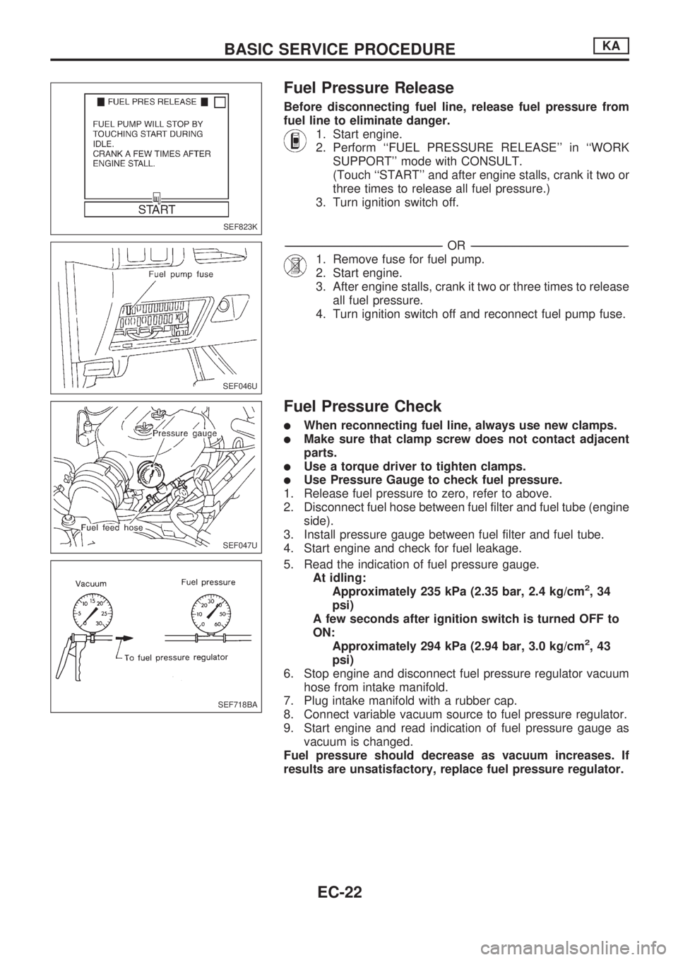
Fuel Pressure Release
Before disconnecting fuel line, release fuel pressure from
fuel line to eliminate danger.
1. Start engine.
2. Perform ``FUEL PRESSURE RELEASE'' in ``WORK
SUPPORT'' mode with CONSULT.
(Touch ``START'' and after engine stalls, crank it two or
three times to release all fuel pressure.)
3. Turn ignition switch off.
-------------------------------------------------------------------------------------------------------------------------------------------------------------------------------------------------------------------------------------------------OR-------------------------------------------------------------------------------------------------------------------------------------------------------------------------------------------------------------------------------------------------
1. Remove fuse for fuel pump.
2. Start engine.
3. After engine stalls, crank it two or three times to release
all fuel pressure.
4. Turn ignition switch off and reconnect fuel pump fuse.
Fuel Pressure Check
lWhen reconnecting fuel line, always use new clamps.
lMake sure that clamp screw does not contact adjacent
parts.
lUse a torque driver to tighten clamps.
lUse Pressure Gauge to check fuel pressure.
1. Release fuel pressure to zero, refer to above.
2. Disconnect fuel hose between fuel filter and fuel tube (engine
side).
3. Install pressure gauge between fuel filter and fuel tube.
4. Start engine and check for fuel leakage.
5. Read the indication of fuel pressure gauge.
At idling:
Approximately 235 kPa (2.35 bar, 2.4 kg/cm
2,34
psi)
A few seconds after ignition switch is turned OFF to
ON:
Approximately 294 kPa (2.94 bar, 3.0 kg/cm
2,43
psi)
6. Stop engine and disconnect fuel pressure regulator vacuum
hose from intake manifold.
7. Plug intake manifold with a rubber cap.
8. Connect variable vacuum source to fuel pressure regulator.
9. Start engine and read indication of fuel pressure gauge as
vacuum is changed.
Fuel pressure should decrease as vacuum increases. If
results are unsatisfactory, replace fuel pressure regulator.
SEF823K
SEF046U
SEF047U
SEF718BA
BASIC SERVICE PROCEDUREKA
EC-22