1998 NISSAN PICK-UP maintenance
[x] Cancel search: maintenancePage 871 of 1659
HEATER &
AIR CONDITIONER
SECTIONHA
CONTENTS
PRECAUTIONS AND PREPARATION..................... 1
Supplemental Restraint System (SRS) ``AIR
BAG'' (4WD models).............................................. 1
Supplemental Restraint System (SRS) ``AIR
BAG'' (2WD models).............................................. 1
Precautions for Working with HFC-134a
(R-134a) ................................................................. 2
General Refrigerant Precautions ........................... 2
Precautions for Refrigerant Connection ................ 2
Precautions for Servicing Compressor .................. 6
Special Service Tools ............................................ 6
HFC-134a (R-134a) Service Tools and
Equipment .............................................................. 8
Precautions for Service Equipment ..................... 10
DESCRIPTION......................................................... 12
Refrigeration Cycle .............................................. 12
Component Layout............................................... 13
Discharge Air Flow............................................... 14
Control Operation................................................. 16
TROUBLE DIAGNOSES......................................... 17
How to Perform Trouble Diagnoses for Quick
and Accurate Repair ............................................ 17
Operational Check ............................................... 18
Symptom Chart .................................................... 20
Preliminary Check ................................................ 21
Performance Test Diagnoses .............................. 24
Performance Chart............................................... 26Trouble Diagnoses for Abnormal Pressure ......... 27
Component Location ............................................ 30
Wiring Diagram - HEATER -................................ 31
Circuit Diagram - Air Conditioner......................... 32
Wiring Diagram - A/C - ........................................ 33
Main Power Supply and Ground Circuit Check... 36
Diagnostic Procedure 1 ....................................... 37
Diagnostic Procedure 2 ....................................... 39
Electrical Components Inspection ....................... 43
Control Linkage Adjustment................................. 45
SERVICE PROCEDURES....................................... 48
HFC-134a (R-134a) Service Procedure .............. 48
Maintenance of Lubricant Quantity in
Compressor.......................................................... 50
Refrigerant Lines.................................................. 52
Checking Refrigerant Leaks ................................ 56
Compressor Mounting.......................................... 58
Compressor - DKV-14C (ZEXEL make) .............. 60
Compressor Clutch - DKV-14C
(ZEXEL make) ..................................................... 60
Thermal Protector - DKV-14C (ZEXEL make) .... 63
Compressor - DKS-17CH (ZEXEL make) ........... 64
Compressor Clutch - DKS-17CH
(ZEXEL make) ..................................................... 64
SERVICE DATA AND SPECIFICATIONS (SDS)... 67
General Specifications ......................................... 67
Inspection and Adjustment .................................. 67
When you read wiring diagrams:
lRead GI section, ``HOW TO READ WIRING DIAGRAMS''.
lSee EL section, ``POWER SUPPLY ROUTING'' for power distribution circuit.
When you perform trouble diagnoses, read GI section, ``HOW TO FOLLOW FLOW
CHART IN TROUBLE DIAGNOSES'' and ``HOW TO PERFORM EFFICIENT DIAGNOSIS
FOR AN ELECTRICAL INCIDENT''.
HA
Page 872 of 1659
Supplemental Restraint System (SRS) ``AIR
BAG'' (4WD models)
The Supplemental Restraint System ``AIR BAG'', used along with a seat belt, helps to reduce the risk or
severity of injury to the driver in a frontal collision. The Supplemental Restraint System consists of air bag
module (located in the center of the steering wheel), diagnosis sensor unit, warning lamp, wiring harness
and spiral cable. Information necessary to service the system safely is included in theRS sectionof this
Service Manual.
WARNING:
lTo avoid rendering the SRS inoperative, which could increase the risk of personal injury or death
in the event of a collision which would result in air bag inflation, all maintenance must be per-
formed by an authorized NISSAN dealer.
lImproper maintenance, including incorrect removal and installation of the SRS, can lead to per-
sonal injury caused by unintentional activation of the system.
lDo not use electrical test equipment on any circuit related to the SRS unless instructed to in this
Service Manual. SRS wiring harnesses are covered with yellow insulation either just before the
harness connectors or for the complete harness, for easy identification.
Supplemental Restraint System (SRS) ``AIR
BAG'' (2WD models)
The Supplemental Restraint System ``AIR BAG'', used along with a seat belt, helps to reduce the risk or
severity of injury to the driver in a frontal collision. The Supplemental Restraint System consists of air bag
module (located in the center of the steering wheel), diagnosis sensor unit, warning lamp and spiral cable.
Information necessary to service the system safely is included in theRS sectionof this Service Manual.
WARNING:
lTo avoid rendering the SRS inoperative, which could increase the risk of personal injury or death
in the event of a collision which would result in air bag inflation, all maintenance must be per-
formed by an authorized NISSAN dealer.
lImproper maintenance, including incorrect removal and installation of the SRS, can lead to per-
sonal injury caused by unintentional activation of the system.
lDo not use electrical test equipment on any circuit related to the SRS.
PRECAUTIONS AND PREPARATION
HA-1
Page 877 of 1659
Precautions for Servicing Compressor
lPlug all openings to prevent moisture and foreign matter from entering.
lWhen the compressor is removed, store it in the same position as it is when mounted on the car.
lWhen replacing or repairing compressor, follow ``Maintenance of Lubricant Quantity in Compres-
sor'' exactly. Refer to HA-50.
lKeep friction surfaces between clutch and pulley clean. If the surface is contaminated, with
lubricant, wipe it off by using a clean waste cloth moistened with thinner.
lAfter compressor service operation, turn the compressor shaft by hand more than five turns in
both directions. This will equally distribute lubricant inside the compressor. After the compres-
sor is installed, let the engine idle and operate the compressor for one hour.
lAfter replacing the compressor magnet clutch, apply voltage to the new one and check for nor-
mal operation.
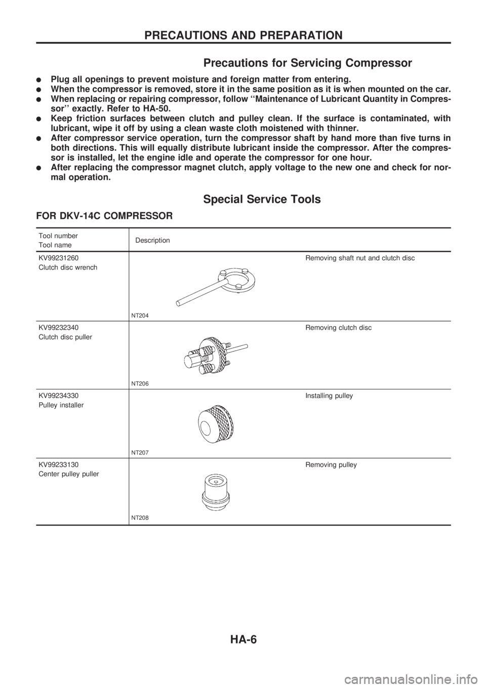
Special Service Tools
FOR DKV-14C COMPRESSOR
Tool number
Tool nameDescription
KV99231260
Clutch disc wrench
NT204
Removing shaft nut and clutch disc
KV99232340
Clutch disc puller
NT206
Removing clutch disc
KV99234330
Pulley installer
NT207
Installing pulley
KV99233130
Center pulley puller
NT208
Removing pulley
PRECAUTIONS AND PREPARATION
HA-6
Page 881 of 1659
Precautions for Service Equipment
RECOVERY/RECYCLING EQUIPMENT
Be certain to follow the manufacturers instructions for machine
operation and machine maintenance. Never introduce any refrig-
erant other than that specified into the machine.
ELECTRONIC LEAK DETECTOR
Be certain to follow the manufacturer's instructions for tester
operation and tester maintenance.
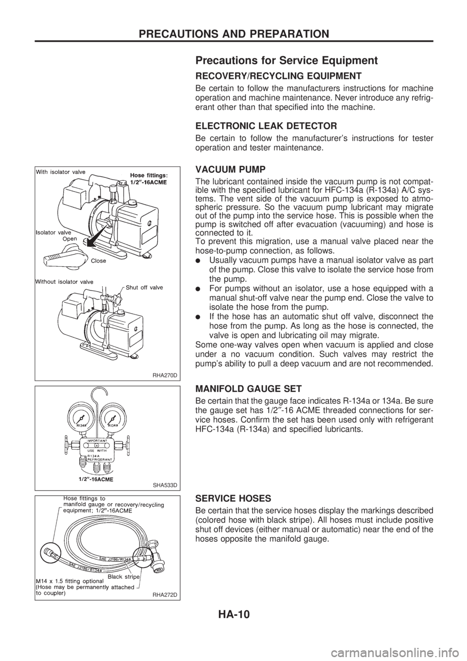
VACUUM PUMP
The lubricant contained inside the vacuum pump is not compat-
ible with the specified lubricant for HFC-134a (R-134a) A/C sys-
tems. The vent side of the vacuum pump is exposed to atmo-
spheric pressure. So the vacuum pump lubricant may migrate
out of the pump into the service hose. This is possible when the
pump is switched off after evacuation (vacuuming) and hose is
connected to it.
To prevent this migration, use a manual valve placed near the
hose-to-pump connection, as follows.
lUsually vacuum pumps have a manual isolator valve as part
of the pump. Close this valve to isolate the service hose from
the pump.
lFor pumps without an isolator, use a hose equipped with a
manual shut-off valve near the pump end. Close the valve to
isolate the hose from the pump.
lIf the hose has an automatic shut off valve, disconnect the
hose from the pump. As long as the hose is connected, the
valve is open and lubricating oil may migrate.
Some one-way valves open when vacuum is applied and close
under a no vacuum condition. Such valves may restrict the
pump's ability to pull a deep vacuum and are not recommended.
MANIFOLD GAUGE SET
Be certain that the gauge face indicates R-134a or 134a. Be sure
the gauge set has 1/2²-16 ACME threaded connections for ser-
vice hoses. Confirm the set has been used only with refrigerant
HFC-134a (R-134a) and specified lubricants.
SERVICE HOSES
Be certain that the service hoses display the markings described
(colored hose with black stripe). All hoses must include positive
shut off devices (either manual or automatic) near the end of the
hoses opposite the manifold gauge.
RHA270D
SHA533D
RHA272D
PRECAUTIONS AND PREPARATION
HA-10
Page 896 of 1659
VA
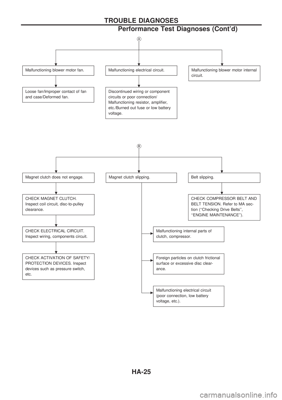
Malfunctioning blower motor fan.Malfunctioning electrical circuit.Malfunctioning blower motor internal
circuit.
Loose fan/Improper contact of fan
and case/Deformed fan.Discontinued wiring or component
circuits or poor connection/
Malfunctioning resistor, amplifier,
etc./Burned out fuse or low battery
voltage.
VB
Magnet clutch does not engage.Magnet clutch slipping.Belt slipping.
CHECK MAGNET CLUTCH.
Inspect coil circuit, disc-to-pulley
clearance.CHECK COMPRESSOR BELT AND
BELT TENSION. Refer to MA sec-
tion (``Checking Drive Belts'',
``ENGINE MAINTENANCE'').
CHECK ELECTRICAL CIRCUIT.
Inspect wiring, components circuit.cMalfunctioning internal parts of
clutch, compressor.
CHECK ACTIVATION OF SAFETY/
PROTECTION DEVICES. Inspect
devices such as pressure switch,
etc.cForeign particles on clutch frictional
surface or excessive disc clear-
ance.
cMalfunctioning electrical circuit
(poor connection, low battery
voltage, etc.).
...
..
...
..
.
.
TROUBLE DIAGNOSES
Performance Test Diagnoses (Cont'd)
HA-25
Page 921 of 1659
Maintenance of Lubricant Quantity in
Compressor
The lubricant used to lubricate the compressor circulates through
the system with the refrigerant. Add lubricant to compressor
when replacing any component or after a large gas leakage
occurred. It is important to maintain the specified amount.
If lubricant quantity is not maintained properly, the following mal-
functions may result:
lLack of lubricant: May lead to a seized compressor
lExcessive lubricant: Inadequate cooling (thermal exchange
interference)
LUBRICANT
Name: Nissan A/C System Oil Type R
Part number: KLH00-PAGR0
CHECKING AND ADJUSTING
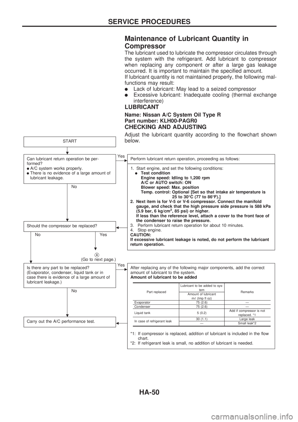
Adjust the lubricant quantity according to the flowchart shown
below.
START
Can lubricant return operation be per-
formed?
lA/C system works properly.lThere is no evidence of a large amount of
lubricant leakage.
No
cYes
Perform lubricant return operation, proceeding as follows:
-----------------------------------------------------------------------------------------------------------------------------------------------------------------------------------------------------------------------------------------------------------------------------------------------------------------------------------------------------------------------------------------------------------------------------------------------------------------------------------------------------------------------------------
1. Start engine, and set the following conditions:
lTest condition
Engine speed: Idling to 1,200 rpm
A/C or AUTO switch: ON
Blower speed: Max. position
Temp. control: Optional [Set so that intake air temperature is
25 to 30ÉC (77 to 86ÉF).]
2. Next item is for V-5 or V-6 compressor. Connect the manifold
gauge, and check that the high pressure side pressure is 588 kPa
(5.9 bar, 6 kg/cm
2, 85 psi) or higher.
If less than the reference level, attach a cover to the front face of
the condenser to raise the pressure.
3. Perform lubricant return operation for about 10 minutes.
4. Stop engine.
CAUTION:
If excessive lubricant leakage is noted, do not perform the lubricant
return operation.
Should the compressor be replaced?
No Yes
b
VA(Go to next page.)
Is there any part to be replaced?
(Evaporator, condenser, liquid tank or in
case there is evidence of a large amount of
lubricant leakage.)
No
cYes
After replacing any of the following major components, add the correct
amount of lubricant to the system.
Amount of lubricant to be added
*1: If compressor is replaced, addition of lubricant is included in the flow
chart.
*2: If refrigerant leak is small, no addition of lubricant is needed.
Carry out the A/C performance test.b
Part replacedLubricant to be added to sys-
tem
Remarks
Amount of lubricant
m!(Imp fl oz)
Evaporator 75 (2.6) Ð
Condenser 75 (2.6) Ð
Liquid tank 5 (0.2)Add if compressor is not
replaced. *1
In case of refrigerant leak30 (1.1) Large leak
Ð Small leak*2
.
.
.
.
.
SERVICE PROCEDURES
HA-50
Page 922 of 1659
VA
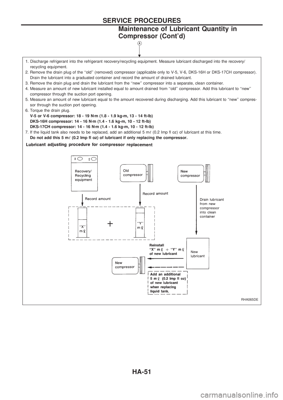
1. Discharge refrigerant into the refrigerant recovery/recycling equipment. Measure lubricant discharged into the recovery/
recycling equipment.
2. Remove the drain plug of the ``old'' (removed) compressor (applicable only to V-5, V-6, DKS-16H or DKS-17CH compressor).
Drain the lubricant into a graduated container and record the amount of drained lubricant.
3. Remove the drain plug and drain the lubricant from the ``new'' compressor into a separate, clean container.
4. Measure an amount of new lubricant installed equal to amount drained from ``old'' compressor. Add this lubricant to ``new''
compressor through the suction port opening.
5. Measure an amount of new lubricant equal to the amount recovered during discharging. Add this lubricant to ``new'' compres-
sor through the suction port opening.
6. Torque the drain plug.
V-5 or V-6 compressor: 18 - 19 Nzm (1.8 - 1.9 kg-m, 13 - 14 ft-lb)
DKS-16H compressor: 14 - 16 Nzm (1.4 - 1.6 kg-m, 10 - 12 ft-lb)
DKS-17CH compressor: 14 - 16 Nzm (1.4 - 1.6 kg-m, 10 - 12 ft-lb)
7. If the liquid tank also needs to be replaced, add an additional 5 m!(0.2 Imp fl oz) of lubricant at this time.
Do not add this 5 m!(0.2 Imp fl oz) of lubricant if only replacing the compressor.
RHA065DE
.
SERVICE PROCEDURES
Maintenance of Lubricant Quantity in
Compressor (Cont'd)
HA-51
Page 927 of 1659
Checking Refrigerant Leaks
PRELIMINARY CHECK
Perform a visual inspection of all refrigeration parts, fittings,
hoses, and components for signs of A/C lubricant leakage, dam-
age and corrosion.
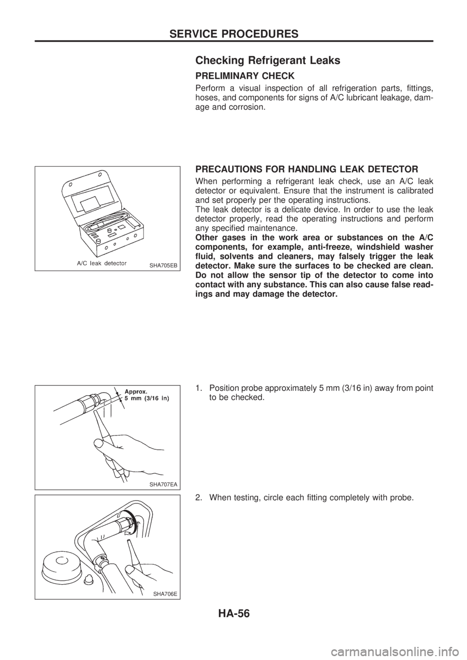
PRECAUTIONS FOR HANDLING LEAK DETECTOR
When performing a refrigerant leak check, use an A/C leak
detector or equivalent. Ensure that the instrument is calibrated
and set properly per the operating instructions.
The leak detector is a delicate device. In order to use the leak
detector properly, read the operating instructions and perform
any specified maintenance.
Other gases in the work area or substances on the A/C
components, for example, anti-freeze, windshield washer
fluid, solvents and cleaners, may falsely trigger the leak
detector. Make sure the surfaces to be checked are clean.
Do not allow the sensor tip of the detector to come into
contact with any substance. This can also cause false read-
ings and may damage the detector.
1. Position probe approximately 5 mm (3/16 in) away from point
to be checked.
2. When testing, circle each fitting completely with probe.
SHA705EB
SHA707EA
SHA706E
SERVICE PROCEDURES
HA-56