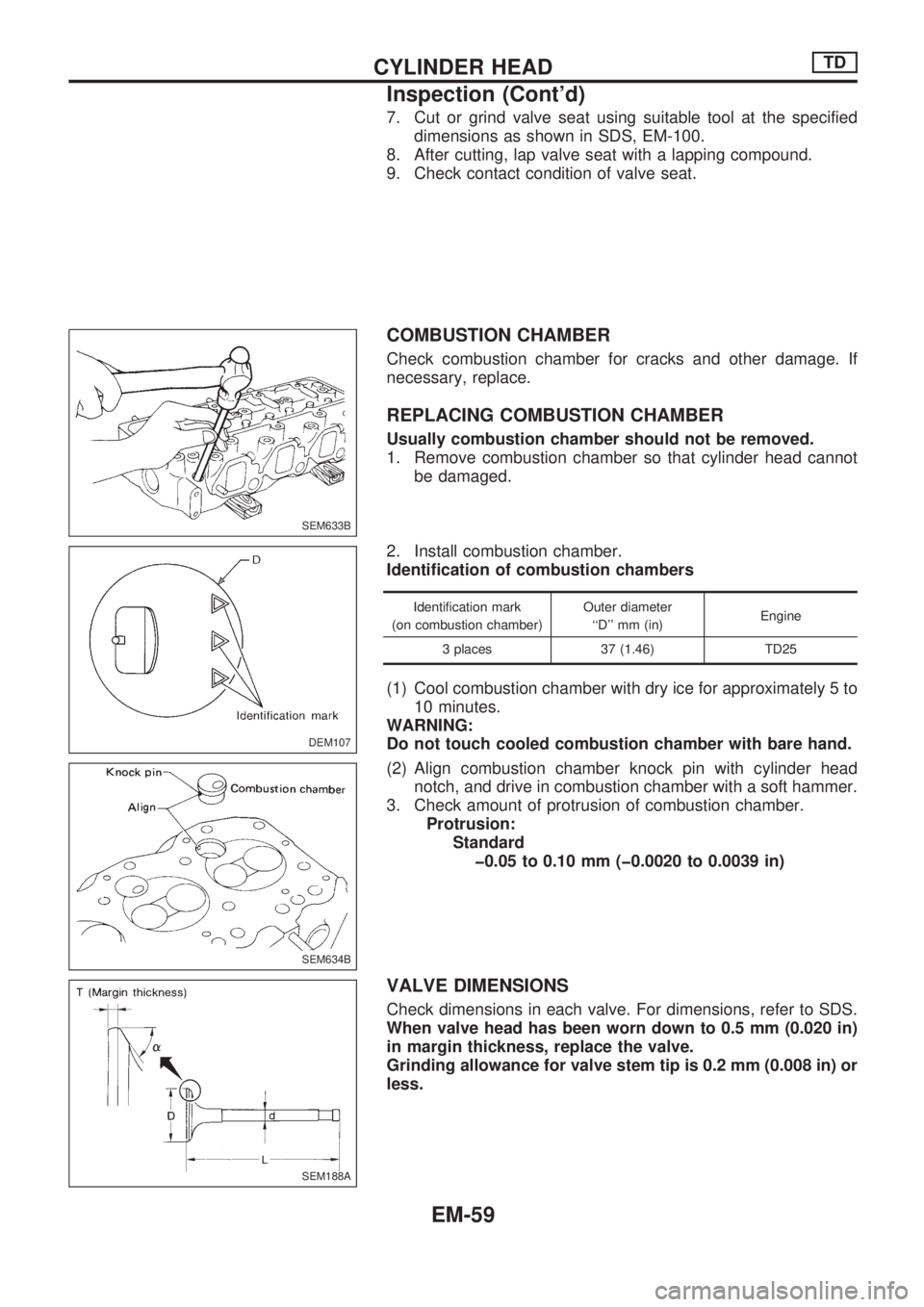
7. Cut or grind valve seat using suitable tool at the specified
dimensions as shown in SDS, EM-100.
8. After cutting, lap valve seat with a lapping compound.
9. Check contact condition of valve seat.
COMBUSTION CHAMBER
Check combustion chamber for cracks and other damage. If
necessary, replace.
REPLACING COMBUSTION CHAMBER
Usually combustion chamber should not be removed.
1. Remove combustion chamber so that cylinder head cannot
be damaged.
2. Install combustion chamber.
Identification of combustion chambers
Identification mark
(on combustion chamber)Outer diameter
``D'' mm (in)Engine
3 places 37 (1.46) TD25
(1) Cool combustion chamber with dry ice for approximately 5 to
10 minutes.
WARNING:
Do not touch cooled combustion chamber with bare hand.
(2) Align combustion chamber knock pin with cylinder head
notch, and drive in combustion chamber with a soft hammer.
3. Check amount of protrusion of combustion chamber.
Protrusion:
Standard
þ0.05 to 0.10 mm (þ0.0020 to 0.0039 in)
VALVE DIMENSIONS
Check dimensions in each valve. For dimensions, refer to SDS.
When valve head has been worn down to 0.5 mm (0.020 in)
in margin thickness, replace the valve.
Grinding allowance for valve stem tip is 0.2 mm (0.008 in) or
less.
SEM633B
DEM107
.
SEM634B
SEM188A
CYLINDER HEADTD
Inspection (Cont'd)
EM-59