Page 42 of 1659
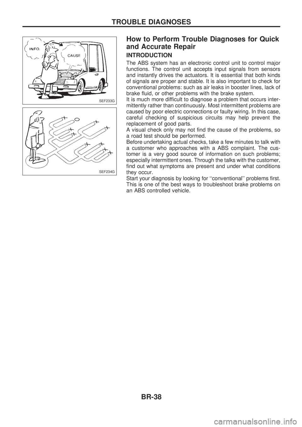
How to Perform Trouble Diagnoses for Quick
and Accurate Repair
INTRODUCTION
The ABS system has an electronic control unit to control major
functions. The control unit accepts input signals from sensors
and instantly drives the actuators. It is essential that both kinds
of signals are proper and stable. It is also important to check for
conventional problems: such as air leaks in booster lines, lack of
brake fluid, or other problems with the brake system.
It is much more difficult to diagnose a problem that occurs inter-
mittently rather than continuously. Most intermittent problems are
caused by poor electric connections or faulty wiring. In this case,
careful checking of suspicious circuits may help prevent the
replacement of good parts.
A visual check only may not find the cause of the problems, so
a road test should be performed.
Before undertaking actual checks, take a few minutes to talk with
a customer who approaches with a ABS complaint. The cus-
tomer is a very good source of information on such problems;
especially intermittent ones. Through the talks with the customer,
find out what symptoms are present and under what conditions
they occur.
Start your diagnosis by looking for ``conventional'' problems first.
This is one of the best ways to troubleshoot brake problems on
an ABS controlled vehicle.
SEF233G
SEF234G
TROUBLE DIAGNOSES
BR-38
Page 43 of 1659
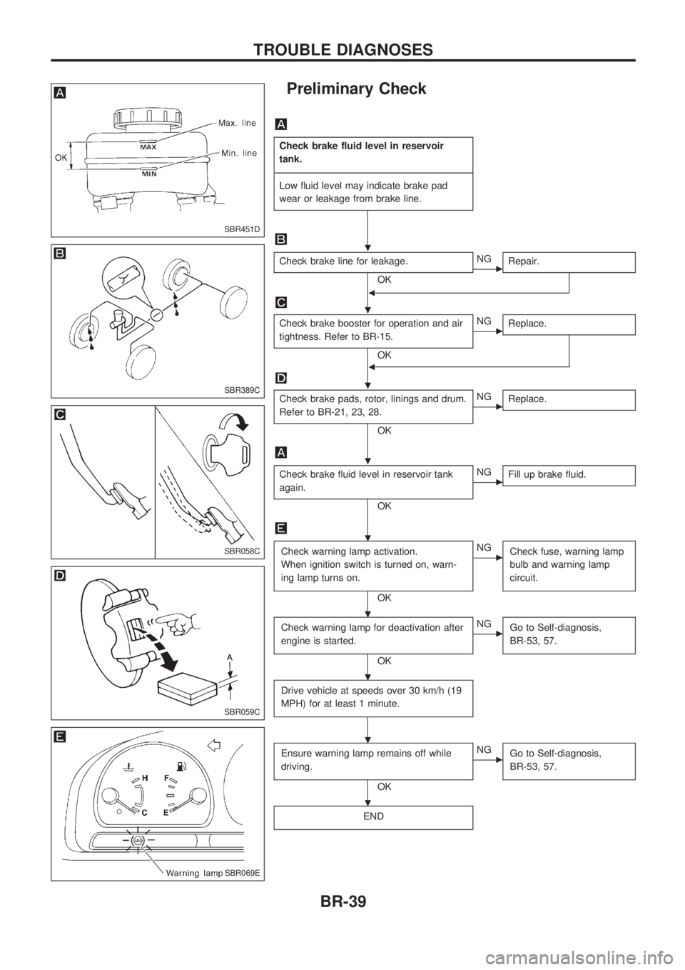
Preliminary Check
Check brake fluid level in reservoir
tank.
-------------------------------------------------------------------------------------------------------------------------------------------------------------------------------------------------------------------------------------------------------------------------------------------------------------
Low fluid level may indicate brake pad
wear or leakage from brake line.
Check brake line for leakage.
OKcNG
Repair.
b
Check brake booster for operation and air
tightness. Refer to BR-15.
OK
cNG
Replace.
b
Check brake pads, rotor, linings and drum.
Refer to BR-21, 23, 28.
OK
cNG
Replace.
Check brake fluid level in reservoir tank
again.
OK
cNG
Fill up brake fluid.
Check warning lamp activation.
When ignition switch is turned on, warn-
ing lamp turns on.
OK
cNG
Check fuse, warning lamp
bulb and warning lamp
circuit.
Check warning lamp for deactivation after
engine is started.
OK
cNG
Go to Self-diagnosis,
BR-53, 57.
Drive vehicle at speeds over 30 km/h (19
MPH) for at least 1 minute.
Ensure warning lamp remains off while
driving.
OK
cNG
Go to Self-diagnosis,
BR-53, 57.
END
SBR451D
SBR389C
SBR058C
SBR059C
SBR069E
.
.
.
.
.
.
.
.
.
TROUBLE DIAGNOSES
BR-39
Page 65 of 1659
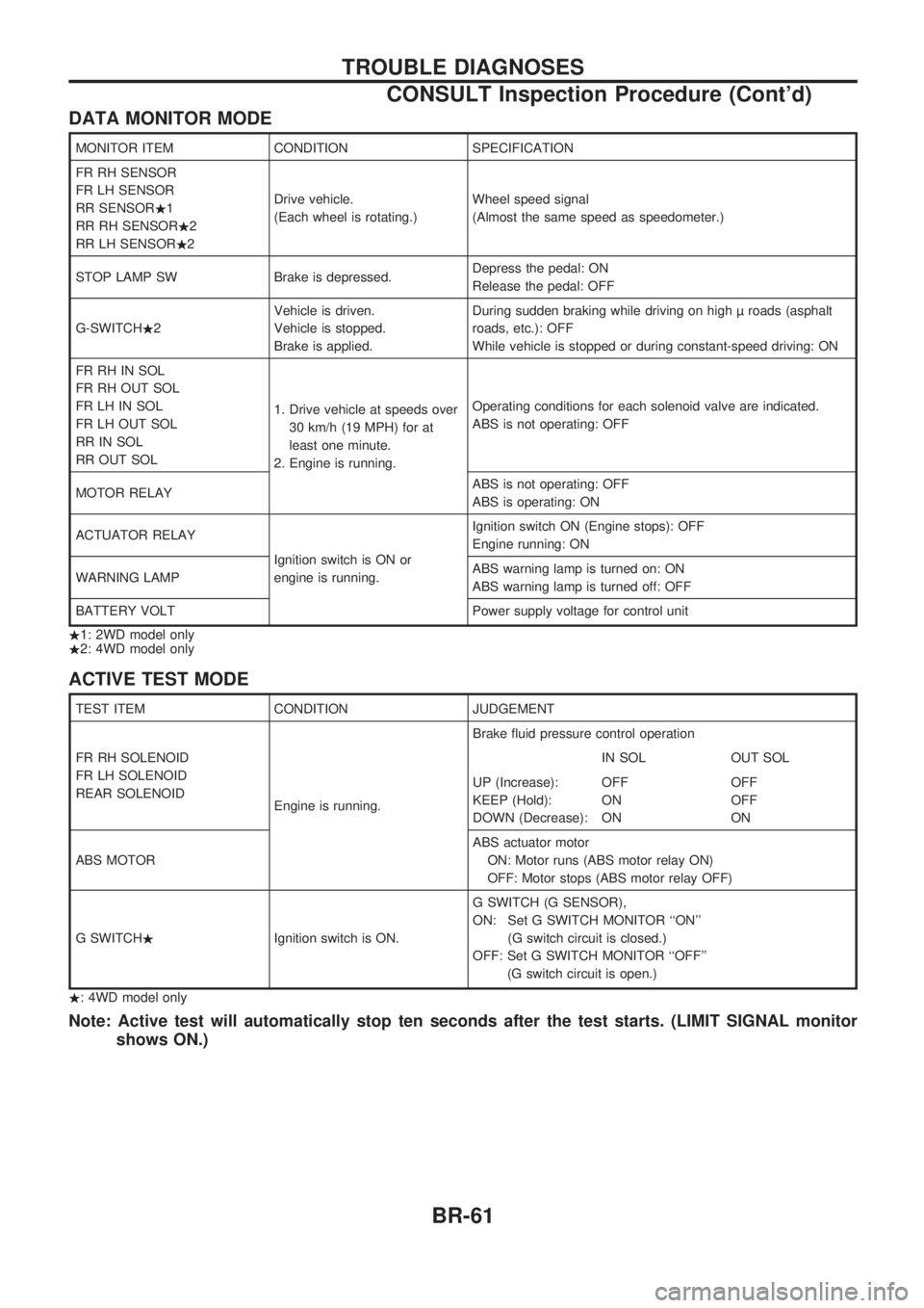
DATA MONITOR MODE
MONITOR ITEM CONDITION SPECIFICATION
FR RH SENSOR
FR LH SENSOR
RR SENSOR.1
RR RH SENSOR.2
RR LH SENSOR.2Drive vehicle.
(Each wheel is rotating.)Wheel speed signal
(Almost the same speed as speedometer.)
STOP LAMP SW Brake is depressed.Depress the pedal: ON
Release the pedal: OFF
G-SWITCH.2Vehicle is driven.
Vehicle is stopped.
Brake is applied.During sudden braking while driving on high roads (asphalt
roads, etc.): OFF
While vehicle is stopped or during constant-speed driving: ON
FR RH IN SOL
FR RH OUT SOL
FR LH IN SOL
FR LH OUT SOL
RR IN SOL
RR OUT SOL1. Drive vehicle at speeds over
30 km/h (19 MPH) for at
least one minute.
2. Engine is running.Operating conditions for each solenoid valve are indicated.
ABS is not operating: OFF
MOTOR RELAYABS is not operating: OFF
ABS is operating: ON
ACTUATOR RELAY
Ignition switch is ON or
engine is running.Ignition switch ON (Engine stops): OFF
Engine running: ON
WARNING LAMPABS warning lamp is turned on: ON
ABS warning lamp is turned off: OFF
BATTERY VOLT Power supply voltage for control unit
.1: 2WD model only
.2: 4WD model only
ACTIVE TEST MODE
TEST ITEM CONDITION JUDGEMENT
FR RH SOLENOID
FR LH SOLENOID
REAR SOLENOID
Engine is running.Brake fluid pressure control operation
IN SOL OUT SOL
UP (Increase):
KEEP (Hold):
DOWN (Decrease):OFF
ON
ONOFF
OFF
ON
ABS MOTORABS actuator motor
ON: Motor runs (ABS motor relay ON)
OFF: Motor stops (ABS motor relay OFF)
G SWITCH.Ignition switch is ON.G SWITCH (G SENSOR),
ON: Set G SWITCH MONITOR ``ON''
(G switch circuit is closed.)
OFF: Set G SWITCH MONITOR ``OFF''
(G switch circuit is open.)
.: 4WD model only
Note: Active test will automatically stop ten seconds after the test starts. (LIMIT SIGNAL monitor
shows ON.)
TROUBLE DIAGNOSES
CONSULT Inspection Procedure (Cont'd)
BR-61
Page 76 of 1659
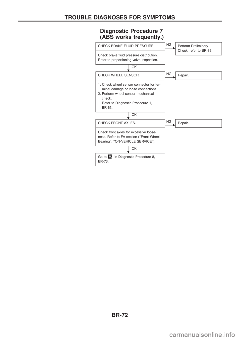
Diagnostic Procedure 7
(ABS works frequently.)
CHECK BRAKE FLUID PRESSURE.
-------------------------------------------------------------------------------------------------------------------------------------------------------------------------------------------------------------------------------------------------------------------------------------------------------------
Check brake fluid pressure distribution.
Refer to proportioning valve inspection.
OK
cNG
Perform Preliminary
Check, refer to BR-39.
CHECK WHEEL SENSOR.
-------------------------------------------------------------------------------------------------------------------------------------------------------------------------------------------------------------------------------------------------------------------------------------------------------------
1. Check wheel sensor connector for ter-
minal damage or loose connections.
2. Perform wheel sensor mechanical
check.
Refer to Diagnostic Procedure 1,
BR-63.
OK
cNG
Repair.
CHECK FRONT AXLES.
-------------------------------------------------------------------------------------------------------------------------------------------------------------------------------------------------------------------------------------------------------------------------------------------------------------
Check front axles for excessive loose-
ness. Refer to FA section (``Front Wheel
Bearing'', ``ON-VEHICLE SERVICE'').
OK
cNG
Repair.
Go toin Diagnostic Procedure 8,
BR-73.
.
.
.
TROUBLE DIAGNOSES FOR SYMPTOMS
BR-72
Page 82 of 1659
General Specifications
2WD MODELS
Applied model Without ABS With ABS
Front brake
CL28VD disc brake
Type
Cylinder bore diameter mm (in) 42.8 (1.685) x 2
Pad dimension mm (in)
Length x width x thickness146.6 x 48.5 x 10.0
(5.77 x 1.909 x 0.394)
Rotor outer diameter x thickness
mm (in)260x26
(10.24 x 1.02)
Rear brake
TypeLT26B drum brake
Wheel cylinder bore diameter
mm (in)23.81 (15/16)
Lining dimension mm (in)
Length x width x thickness249.6 x 50 x 5.5
(9.83 x 1.97 x 0.217)
Drum inner diameter mm (in) 260 (10.24)
Master cylinder bore diameter
mm (in)23.81 (15/16) 25.4 (1)
Control valve
TypeLSV
Split point x reducing ratio
kPa (bar, kg/cm
2, psi)(Variable) x 0.15
Brake booster
ModelM195T
Diaphragm diameter mm (in)Primary: 205 (8.07)
Secondary: 180 (7.09)
Recommended brake fluid DOT 3 or DOT 4*1
*1: Refer to MA section (``Fluids and Lubricants'', ``RECOMMENDED FLUIDS AND LUBRICANTS'').
SERVICE DATA AND SPECIFICATIONS (SDS)
BR-78
Page 83 of 1659
4WD MODELS
Applied modelAll
Front brake
TypeCL28VD disc brake
Cylinder bore diameter mm (in) 42.8 (1.685) x 2
Pad dimension mm (in)
Length x width x thickness146.6 x 48.5 x 10
(5.77 x 1.909 x 0.39)
Rotor outer diameter x thickness
mm (in)277 x 26 (10.91 x 1.02)
Rear brake
TypeLT30A drum brake
Wheel cylinder bore diameter
mm (in)22.22 (7/8)
Lining dimension mm (in)
Length x width x thickness296.0 x 50.0 x 6.1 (11.65 x 1.969 x 0.240)
Drum inner diameter mm (in) 295 (11.61)
Master cylinder bore diameter
mm (in)23.81 (15/16)
Control valve
TypeLSV
Split point x reducing ratio
kPa (bar, kg/cm
2, psi)(Variable) x 0.15
Brake booster
ModelM215T
Diaphragm diameter mm (in)Primary: 230 (9.06)
Secondary: 205 (8.07)
Recommended brake fluid DOT 3 or DOT 4*1
*1: Refer to MA section (``Fluids and Lubricants'', ``RECOMMENDED FLUIDS AND LUBRICANTS'').
SERVICE DATA AND SPECIFICATIONS (SDS)
General Specifications (Cont'd)
BR-79
Page 86 of 1659
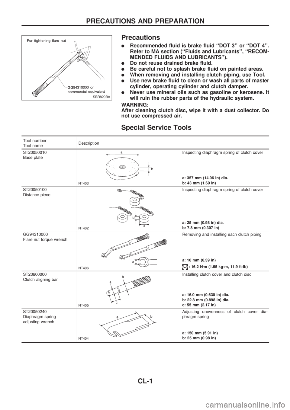
Precautions
lRecommended fluid is brake fluid ``DOT 3'' or ``DOT 4''.
Refer to MA section (``Fluids and Lubricants'', ``RECOM-
MENDED FLUIDS AND LUBRICANTS'').
lDo not reuse drained brake fluid.
lBe careful not to splash brake fluid on painted areas.
lWhen removing and installing clutch piping, use Tool.
lUse new brake fluid to clean or wash all parts of master
cylinder, operating cylinder and clutch damper.
lNever use mineral oils such as gasoline or kerosene. It
will ruin the rubber parts of the hydraulic system.
WARNING:
After cleaning clutch disc, wipe it with a dust collector. Do
not use compressed air.
Special Service Tools
Tool number
Tool nameDescription
ST20050010
Base plate
NT403
Inspecting diaphragm spring of clutch cover
a: 357 mm (14.06 in) dia.
b: 43 mm (1.69 in)
ST20050100
Distance piece
NT402
Inspecting diaphragm spring of clutch cover
a: 25 mm (0.98 in) dia.
b: 7.8 mm (0.307 in)
GG94310000
Flare nut torque wrench
NT406
Removing and installing each clutch piping
a: 10 mm (0.39 in)
: 16.2 Nzm (1.65 kg-m, 11.9 ft-lb)
ST20600000
Clutch aligning bar
NT405
Installing clutch cover and clutch disc
a: 16.0 mm (0.630 in) dia.
b: 22.8 mm (0.898 in) dia.
c: 55 mm (2.17 in)
ST20050240
Diaphragm spring
adjusting wrench
NT404
Adjusting unevenness of clutch cover dia-
phragm spring
a: 150 mm (5.91 in)
b: 25 mm (0.98 in)
SBR820BA
PRECAUTIONS AND PREPARATION
CL-1
Page 90 of 1659
Adjusting Clutch Pedal
1. Adjust pedal height with pedal stopper.
2. Adjust pedal free play with push rod.
Air Bleeding Procedure
Bleed air according to the following procedure.
Bleed the air from the master cylinder (RHD models only)
and then the operating cylinder.
1. Fill the master cylinder reservoir tank with new brake fluid.
2. Connect a transparent vinyl hose to the air bleeder.
3. Slowly depress the clutch pedal to its full stroke length and
release it completely. Repeat this operation several times at
2 to 3 second intervals.
4. Open the air bleeder with the clutch pedal fully depressed.
5. Close the air bleeder.
6. Release the clutch pedal and wait at least 5 seconds.
7. Repeat steps 3 through 6 above until air bubbles no longer
appear in the brake fluid.
SCL742-A
.LHD model
221 - 231 mm (8.70 - 0.09 in)
RHD model
195 - 205 mm (7.68 - 8.07 in)
Pedal free play ``A'':
1 - 1.5 mm (0.039 - 0.059 in)
SCL203
INSPECTION AND ADJUSTMENT
CL-5