1998 NISSAN PICK-UP oil level
[x] Cancel search: oil levelPage 808 of 1659
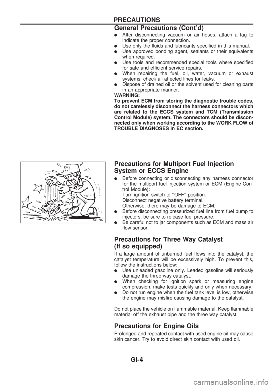
lAfter disconnecting vacuum or air hoses, attach a tag to
indicate the proper connection.
lUse only the fluids and lubricants specified in this manual.
lUse approved bonding agent, sealants or their equivalents
when required.
lUse tools and recommended special tools where specified
for safe and efficient service repairs.
lWhen repairing the fuel, oil, water, vacuum or exhaust
systems, check all affected lines for leaks.
lDispose of drained oil or the solvent used for cleaning parts
in an appropriate manner.
WARNING:
To prevent ECM from storing the diagnostic trouble codes,
do not carelessly disconnect the harness connectors which
are related to the ECCS system and TCM (Transmission
Control Module) system. The connectors should be discon-
nected only when working according to the WORK FLOW of
TROUBLE DIAGNOSES in EC section.
Precautions for Multiport Fuel Injection
System or ECCS Engine
lBefore connecting or disconnecting any harness connector
for the multiport fuel injection system or ECM (Engine Con-
trol Module):
Turn ignition switch to ``OFF'' position.
Disconnect negative battery terminal.
Otherwise, there may be damage to ECM.
lBefore disconnecting pressurized fuel line from fuel pump to
injectors, be sure to release fuel pressure.
lBe careful not to jar components such as ECM and mass air
flow sensor.
Precautions for Three Way Catalyst
(If so equipped)
If a large amount of unburned fuel flows into the catalyst, the
catalyst temperature will be excessively high. To prevent this,
follow the instructions below:
lUse unleaded gasoline only. Leaded gasoline will seriously
damage the three way catalyst.
lWhen checking for ignition spark or measuring engine
compression, make tests quickly and only when necessary.
lDo not run engine when the fuel tank level is low, otherwise
the engine may misfire causing damage to the catalyst.
Do not place the vehicle on flammable material. Keep flammable
material off the exhaust pipe and the three way catalyst.
Precautions for Engine Oils
Prolonged and repeated contact with used engine oil may cause
skin cancer. Try to avoid direct skin contact with used oil.
SGI787
PRECAUTIONS
General Precautions (Cont'd)
GI-4
Page 867 of 1659

HLC - Wiring diagram ................................ EL-130
HORN - Wiring diagram ............................. EL-132
H/SEAT - Wiring diagram........................... EL-152
Harness connector ......................................... EL-2
Harness connector inspection ...................... GI-18
Harness layout ........................................... EL-220
Hazard warning lamp ................................... EL-74
Headlamp ..................................................... EL-44
Headlamp aiming control ............................. EL-63
Headlamp leveler - See Headlamp
aiming control ........................................... EL-63
Headlamp washer ...................................... EL-130
Heated oxygen sensor (HO2S) ................. EC-123
Heated oxygen sensor heater ................... EC-127
Heated oxygen sensor inspection ............... MA-22
Heated seat .................................................. BT-32
Heated seat ................................................ EL-152
Height (Dimensions) ..................................... GI-44
Hood ............................................................... BT-5
Horn ............................................................ EL-132
How to erase DTC for ECCS OBD
system ...................................................... EC-36
I
IACV-AAC valve .................................EC-131, 135
IACV-FICD solenoid valve
(KA24 engine) ........................................ EC-168
IACV-FICD solenoid valve
(TD25 engine) ........................................ EC-231
IATS - Wiring diagram ............................... EC-110
IGN/SG - Wiring diagram .......................... EC-101
ILL - Wiring diagram..................................... EL-81
INJECT - Wiring diagram .......................... EC-144
INT/L - Wiring diagram ................................. EL-85
Identification plate ......................................... GI-42
Idle mixture ratio .......................................... EC-25
Idle speed .................................................... EC-25
Idle speed inspection .................................. MA-30
Ignition coil ................................................. EC-105
Ignition timing............................................... EC-25
Ignition wire inspection ................................ MA-21
Illumination ................................................... EL-81
Injection nozzle inspection .......................... MA-29
Injection nozzle .......................................... EC-186
Injector ............................................... EC-144, 148
Injector removal and installation .................. EC-23
Instrument panel .......................................... BT-12
Intake air temperature sensor ................... EC-109
Intake door control linkage
adjustment................................................ HA-47
Intake manifold .............................................. EM-9
Interior lamp ................................................. EL-85
Interior .......................................................... BT-15
J
Jacking points ................................................GI-47Journal bearing assembly
(propeller shaft) ........................................ PD-11
Journal bearing disassembly
(propeller shaft) ........................................ PD-10
Jump seat..................................................... BT-34
K
Keyless entry system - See Multi-remote
control system .............................................EL-173
Knuckle spindle ............................................ FA-18
L
LSV (Load sensing valve)...............................BR-7
Leaf spring (rear) ......................................... RA-13
Length (Dimensions) ..................................... GI-44
License lamp ................................................ EL-66
Lifting points .................................................. GI-47
Limited slip diff. adjustment (C200) ............. PD-41
Limited slip diff. adjustment (H233B) .......... PD-63
Limited slip diff. assembly (C200) ............... PD-43
Limited slip diff. assembly (H233B) ............. PD-64
Limited slip diff. disassembly (C200)........... PD-39
Limited slip diff. disassembly (H233B) ........ PD-61
Limited slip diff. inspection (C200) .............. PD-40
Limited slip diff. inspection (H233B) ............ PD-62
Liquid gasket application ............................... EM-1
Location of electrical units.......................... EL-217
Lock, door .................................................... BT-10
Lubricant (R134a) A/C ................................. HA-50
Lubricants .................................................... MA-12
Lubrication circuit (engine)
(KA24 engine) ............................................ LC-3
Lubrication circuit (engine)
(TD25 engine) .......................................... LC-12
Lubrication-locks, hinges and hood
latches ..................................................... MA-39
M
M/T major overhaul (FS5R30A) ...................MT-35
M/T major overhaul (FS5W71C) ................. MT-14
M/T removal and installation ....................... MT-11
MAFS - Wiring diagram ............................... EC-91
MAIN - Wiring diagram ................................ EC-76
METER - Wiring diagram ............................. EL-90
MIL & Data link connectors ....................... EC-173
MIRROR - Wiring diagram ......................... EL-150
MULTI - Wiring diagram ............................. EL-175
Main drive gear (M/T) (FS5R30A)............... MT-36
Main drive gear (M/T) (FS5W71C).............. MT-15
Main gear (Transfer) ...................................... TF-9
Mainshaft (M/T) (FS5R30A) ........................ MT-36
Mainshaft (M/T) (FS5W71C) ....................... MT-15
Mainshaft (Transfer) ....................................... TF-9
Maintenance (engine) (KA24 engine) ......... MA-15
ALPHABETICAL INDEX
IDX-5
Page 868 of 1659
Maintenance (engine) (TD25 engine) ......... MA-23
Major overhaul (Transfer)............................... TF-8
Malfunction indicator lamp (MIL) ................. EC-38
Manifold tightening torque (intake &
exhaust) ................................................... MA-23
Manual-lock free-running hub ...................... FA-14
Manual steering gear ................................... ST-13
Manual transmission number........................ GI-43
Manual transmission oil replacement.......... MA-32
Mass air flow sensor (MAFS) ...................... EC-89
Master cylinder (brake) ................................ BR-12
Master cylinder (clutch) .................................. CL-6
Mirror, door................................................... BT-39
Mode door control linkage adjustment ........ HA-46
Model variation.............................................. GI-37
Molding - See Exterior ................................. BT-24
Multi-remote control system ....................... EL-173
Multiport fuel injection (MFI) system ........... EC-14
N
NATS (Nissan Anti-theft System)
precautions .......................................................GI-2
NATS (Nissan Anti-theft System)............... EL-183
NATS - Wiring diagram .............................. EL-185
Neutral position switch (M/T)....................... MT-14
Neutral position switch............................... EC-136
O
Oil change (capacity)....................................MA-12
Oil change (interval) ...................................... MA-5
Oil cooler (engine)........................................ LC-17
Oil jet ............................................................ LC-18
Oil pan (engine) (KA24 engine) .................. EM-11
Oil pan (engine) (TD25 engine) .................. EM-52
Oil pressure (engine) (KA24 engine) ............. LC-4
Oil pressure (engine) (TD25 engine) ........... LC-13
Oil pressure relief valve (engine)
(KA24 engine) ............................................ LC-5
Oil pressure relief valve (engine)
(TD25 engine) .......................................... LC-16
Oil pump (engine) (KA24 engine) .................. LC-4
Oil pump (engine) (TD25 engine) ................ LC-14
Oil pump regulator valve (engine)
(KA24 engine) ............................................ LC-5
Oil pump regulator valve (engine)
(TD25 engine) .......................................... LC-17
Oil seal replacement (engine)
(KA24 engine).......................................... EM-22
Oil seal replacement (engine)
(TD25 engine).......................................... EM-67
Oil seal replacement (front of final
drive) ........................................................ PD-12
Operating cylinder (clutch) ............................. CL-8
Outside mirror - See Door mirror ................. BT-39
Oversize piston............................................ EM-95
P
P/ANT - Wiring diagram ..............................EL-147
PCV (positive crankcase ventilation) ......... EC-193
PCV filter replacement ................................ MA-21
PCV system inspection ............................... MA-21
PGC/V - Wiring diagram ............................ EC-141
PLA - Wiring diagram ................................ EC-222
PNP/SW - Wiring diagram ......................... EC-137
POWER - Wiring diagram .............................. EL-6
PST/SW - Wiring diagram ......................... EC-157
Pantograph jack ............................................ GI-47
Parking brake control................................... BR-30
Parking lamp ................................................ EL-66
Periodic maintenance .................................... MA-5
Pilot bushing replacement
(KA24 engine).......................................... EM-48
Pilot bushing replacement
(TD25 engine).......................................... EM-79
Piston assembly (KA24 engine) .................. EM-45
Piston assembly (TD25 engine) .................. EM-86
Piston pin inspection (KA24 engine) ........... EM-39
Piston pin inspection (TD25 engine) ........... EM-76
Piston ring inspection (KA24 engine).......... EM-40
Piston ring inspection (TD25 engine).......... EM-76
Piston to bore clearance
(KA24 engine).......................................... EM-41
Piston to bore clearance
(TD25 engine).......................................... EM-75
Power door lock ......................................... EL-166
Power door mirror ...................................... EL-150
Power steering fluid level .................. MA-37, ST-4
Power steering gear (PB48S) ...................... ST-20
Power steering gear (PB59K) ...................... ST-28
Power steering hydraulic system ................... ST-7
Power steering oil pressure switch............ EC-157
Power steering oil pump .............................. ST-34
Power steering system bleeding .................... ST-5
Power supply routing...................................... EL-5
Power transistor & ignition coil .................. EC-105
Power window ............................................ EL-154
Pre-delivery inspection .................................. MA-3
Precautions (General) ..................................... GI-2
Pressure plate - See Clutch cover............... CL-13
Priming pump............................................. EC-192
Propeller shaft................................................ PD-6
Propeller shaft greasing .............................. MA-33
Propeller shaft inspection ............................ MA-33
Propeller shaft vibration ................................. PD-8
Push rod ...................................................... EM-60
Q
Quick-glow system check ...........................EC-203
R
R/FOG - Wiring diagram ...............................EL-72
ALPHABETICAL INDEX
IDX-6
Page 869 of 1659
Radiator (KA24 engine) ................................. LC-9
Radiator (TD25 engine) ............................... LC-24
Rear axle ....................................................... RA-5
Rear body..................................................... BT-40
Rear case (Transfer) ...................................... TF-8
Rear combination lamp removal and
installation................................................. BT-24
Rear cover gasket replacement diff. ........... PD-13
Rear door ..................................................... BT-11
Rear drum brake.......................................... BR-26
Rear fog lamp............................................... EL-72
Rear seat belt ................................................ RS-4
Rear seat...................................................... BT-33
Rear suspension .......................................... RA-12
Rear window defogger ............................... EL-135
Refrigerant connection precaution................. HA-2
Refrigerant discharging evacuating
charging ................................................... HA-49
Refrigerant general precaution ...................... HA-2
Refrigerant lines........................................... HA-52
Refrigeration cycle ....................................... HA-12
Release bearing (clutch) ................................ CL-9
Removal and installation (Transfer) ............... TF-6
Resistor ...................................................... EC-105
Reverse idler shaft (M/T) (FS5R30A) ......... MT-36
Reverse idler shaft (M/T) (FS5W71C) ........ MT-15
Reverse lamp switch (M/T) - See
Back-up lamp switch (M/T) ........................ MT-9
Reverse main gear (M/T) (FS5R30A) ......... MT-36
Reverse main gear (M/T) (FS5W71C) ........ MT-15
Ring gear diff. inspection (C200)................. PD-38
Ring gear diff. inspection (H233B) .............. PD-60
Road wheel size ........................................... GI-46
Roof trim....................................................... BT-21
Room lamp - See Interior lamp.................... EL-85
Rotor disc (front) .......................................... FA-16
S
S/SIG - Wiring diagram...............................EC-149
SAE J1930 terminology list........................... GI-55
SMJ (super multiple junction) .................... Foldout
SRS - See Supplemental Restraint
System ....................................................... RS-6
SRS Trouble diagnoses
(2WD models) .......................................... RS-17
SRS Trouble diagnoses
(4WD models) .......................................... RS-22
START - Wiring diagram .............................. EL-26
SWL/V - Wiring diagram ............................ EC-163
Screw jack..................................................... GI-48
Seal - See Exterior....................................... BT-24
Seat belt inspection ..................................... MA-40
Seat belt, front ............................................... RS-3
Seat belt, rear ................................................ RS-4
Seat, front..................................................... BT-30
Seat, rear ..................................................... BT-33
Self-diagnostic results.................................. EC-38
Shift control (Transfer) ................................. TF-10Shift control components (M/T)
(FS5R30A) ................................................MT-38
Shift control components (M/T)
(FS5W71C) .............................................. MT-17
Shift fork (M/T) (FS5R30A) ......................... MT-38
Shift fork (M/T) (FS5W71C) ........................ MT-17
Shift lever (FS5R30A) ................................. MT-38
Shift lever (FS5W71C) ................................ MT-17
Shock absorber (front) ................................. FA-28
Shock absorber (rear).................................. RA-13
Side bearing preload (R180A) ..................... PD-23
Side bearing preload (C200) ....................... PD-45
Side trim ....................................................... BT-15
Side window ................................................. BT-38
Spark plug replacement .............................. MA-20
Spiral cable .................................................. RS-11
Spot lamp ..................................................... EL-85
Stabilizer bar (front) ..................................... FA-31
Standardized relay ......................................... EL-3
Start signal ................................................. EC-149
Starter ........................................................... EL-33
Starting system............................................. EL-26
Steering gear and linkage inspection.......... MA-37
Steering gear oil level ................................. MA-38
Steering knuckle........................................... FA-18
Steering linkage ........................................... ST-37
Steering wheel and column ........................... ST-9
Steering wheel play........................................ ST-6
Steering wheel turning force .......................... ST-6
Striking rod (M/T) (FS5R30A) ..................... MT-38
Striking rod (M/T) (FS5W71C) .................... MT-17
Sub-gear (M/T) (FS5R30A) ......................... MT-36
Sub-gear (M/T) (FS5W71C) ........................ MT-15
Sunroof ......................................................... BT-35
Supplemental Restraint System .................... RS-6
Supplemental restraint system - Wiring
diagram (2WD models) ............................ RS-18
Supplemental restraint system - Wiring
diagram (4WD models) ............................ RS-26
Swirl control valve control solenoid
valve ....................................................... EC-161
Symbols and abbreviations............................. GI-8
Synchronizer (M/T) (FS5R30A) ................... MT-36
Synchronizer (M/T) (FS5W71C) .................. MT-15
T
TAIL/L - Wiring diagram ................................EL-66
TPS - Wiring diagram ................................ EC-115
TURN - Wiring diagram................................ EL-75
Tail lamp ....................................................... EL-66
Temperature control cable and linkage
adjustment................................................ HA-47
Tension rod (front) ....................................... FA-33
Thermal protector ........................................ HA-45
Thermo control amp .................................... HA-44
Thermostat (KA24 engine) ............................. LC-8
Thermostat (TD25 engine) ........................... LC-23
Three way catalyst precautions ...................... GI-4
ALPHABETICAL INDEX
IDX-7
Page 921 of 1659
Maintenance of Lubricant Quantity in
Compressor
The lubricant used to lubricate the compressor circulates through
the system with the refrigerant. Add lubricant to compressor
when replacing any component or after a large gas leakage
occurred. It is important to maintain the specified amount.
If lubricant quantity is not maintained properly, the following mal-
functions may result:
lLack of lubricant: May lead to a seized compressor
lExcessive lubricant: Inadequate cooling (thermal exchange
interference)
LUBRICANT
Name: Nissan A/C System Oil Type R
Part number: KLH00-PAGR0
CHECKING AND ADJUSTING
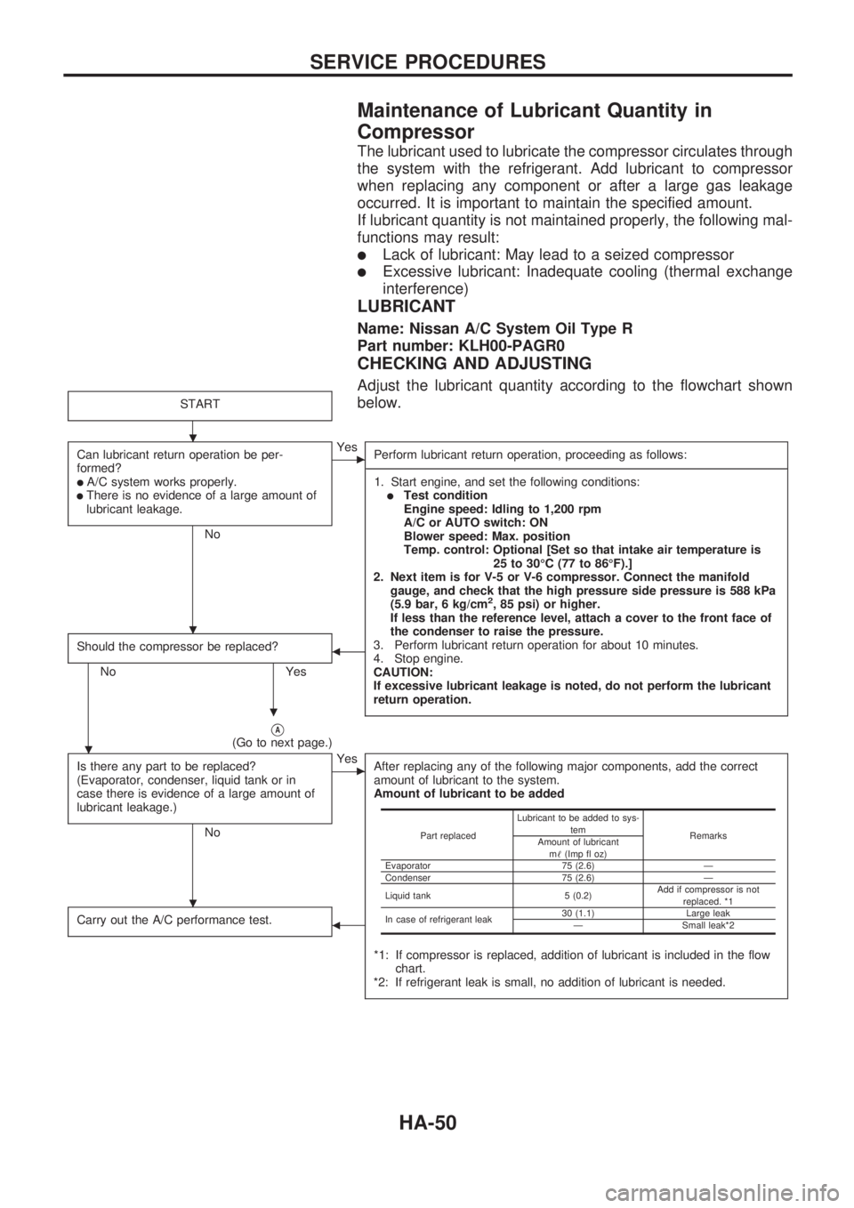
Adjust the lubricant quantity according to the flowchart shown
below.
START
Can lubricant return operation be per-
formed?
lA/C system works properly.lThere is no evidence of a large amount of
lubricant leakage.
No
cYes
Perform lubricant return operation, proceeding as follows:
-----------------------------------------------------------------------------------------------------------------------------------------------------------------------------------------------------------------------------------------------------------------------------------------------------------------------------------------------------------------------------------------------------------------------------------------------------------------------------------------------------------------------------------
1. Start engine, and set the following conditions:
lTest condition
Engine speed: Idling to 1,200 rpm
A/C or AUTO switch: ON
Blower speed: Max. position
Temp. control: Optional [Set so that intake air temperature is
25 to 30ÉC (77 to 86ÉF).]
2. Next item is for V-5 or V-6 compressor. Connect the manifold
gauge, and check that the high pressure side pressure is 588 kPa
(5.9 bar, 6 kg/cm
2, 85 psi) or higher.
If less than the reference level, attach a cover to the front face of
the condenser to raise the pressure.
3. Perform lubricant return operation for about 10 minutes.
4. Stop engine.
CAUTION:
If excessive lubricant leakage is noted, do not perform the lubricant
return operation.
Should the compressor be replaced?
No Yes
b
VA(Go to next page.)
Is there any part to be replaced?
(Evaporator, condenser, liquid tank or in
case there is evidence of a large amount of
lubricant leakage.)
No
cYes
After replacing any of the following major components, add the correct
amount of lubricant to the system.
Amount of lubricant to be added
*1: If compressor is replaced, addition of lubricant is included in the flow
chart.
*2: If refrigerant leak is small, no addition of lubricant is needed.
Carry out the A/C performance test.b
Part replacedLubricant to be added to sys-
tem
Remarks
Amount of lubricant
m!(Imp fl oz)
Evaporator 75 (2.6) Ð
Condenser 75 (2.6) Ð
Liquid tank 5 (0.2)Add if compressor is not
replaced. *1
In case of refrigerant leak30 (1.1) Large leak
Ð Small leak*2
.
.
.
.
.
SERVICE PROCEDURES
HA-50
Page 943 of 1659
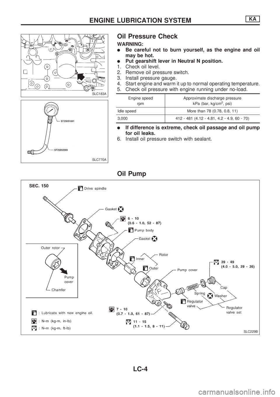
Oil Pressure Check
WARNING:
lBe careful not to burn yourself, as the engine and oil
may be hot.
lPut gearshift lever in Neutral N position.
1. Check oil level.
2. Remove oil pressure switch.
3. Install pressure gauge.
4. Start engine and warm it up to normal operating temperature.
5. Check oil pressure with engine running under no-load.
Engine speed
rpmApproximate discharge pressure
kPa (bar, kg/cm2, psi)
Idle speed More than 78 (0.78, 0.8, 11)
3,000 412 - 481 (4.12 - 4.81, 4.2 - 4.9, 60 - 70)
lIf difference is extreme, check oil passage and oil pump
for oil leaks.
6. Install oil pressure switch with sealant.
Oil Pump
SLC183A
SLC770A
SLC229B
ENGINE LUBRICATION SYSTEMKA
LC-4
Page 952 of 1659
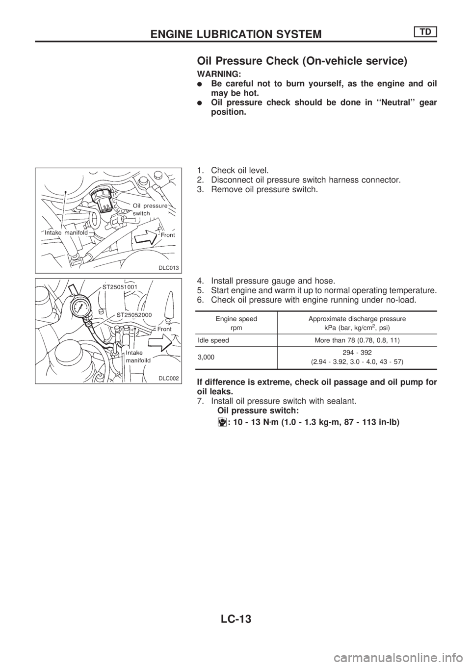
Oil Pressure Check (On-vehicle service)
WARNING:
lBe careful not to burn yourself, as the engine and oil
may be hot.
lOil pressure check should be done in ``Neutral'' gear
position.
1. Check oil level.
2. Disconnect oil pressure switch harness connector.
3. Remove oil pressure switch.
4. Install pressure gauge and hose.
5. Start engine and warm it up to normal operating temperature.
6. Check oil pressure with engine running under no-load.
Engine speed
rpmApproximate discharge pressure
kPa (bar, kg/cm2, psi)
Idle speed More than 78 (0.78, 0.8, 11)
3,000294 - 392
(2.94 - 3.92, 3.0 - 4.0, 43 - 57)
If difference is extreme, check oil passage and oil pump for
oil leaks.
7. Install oil pressure switch with sealant.
Oil pressure switch:
:10-13Nzm (1.0 - 1.3 kg-m, 87 - 113 in-lb)
DLC013
DLC002
ENGINE LUBRICATION SYSTEMTD
LC-13
Page 972 of 1659
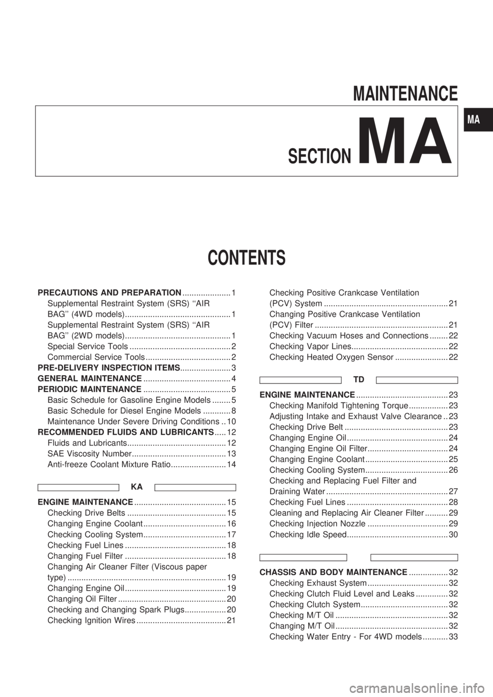
MAINTENANCE
SECTION
MA
CONTENTS
PRECAUTIONS AND PREPARATION..................... 1
Supplemental Restraint System (SRS) ``AIR
BAG'' (4WD models).............................................. 1
Supplemental Restraint System (SRS) ``AIR
BAG'' (2WD models).............................................. 1
Special Service Tools ............................................ 2
Commercial Service Tools ..................................... 2
PRE-DELIVERY INSPECTION ITEMS...................... 3
GENERAL MAINTENANCE...................................... 4
PERIODIC MAINTENANCE...................................... 5
Basic Schedule for Gasoline Engine Models ........ 5
Basic Schedule for Diesel Engine Models ............ 8
Maintenance Under Severe Driving Conditions .. 10
RECOMMENDED FLUIDS AND LUBRICANTS..... 12
Fluids and Lubricants........................................... 12
SAE Viscosity Number......................................... 13
Anti-freeze Coolant Mixture Ratio........................ 14
KA
ENGINE MAINTENANCE........................................ 15
Checking Drive Belts ........................................... 15
Changing Engine Coolant .................................... 16
Checking Cooling System.................................... 17
Checking Fuel Lines ............................................ 18
Changing Fuel Filter ............................................ 18
Changing Air Cleaner Filter (Viscous paper
type) ..................................................................... 19
Changing Engine Oil ............................................ 19
Changing Oil Filter ............................................... 20
Checking and Changing Spark Plugs.................. 20
Checking Ignition Wires ....................................... 21Checking Positive Crankcase Ventilation
(PCV) System ...................................................... 21
Changing Positive Crankcase Ventilation
(PCV) Filter .......................................................... 21
Checking Vacuum Hoses and Connections ........ 22
Checking Vapor Lines.......................................... 22
Checking Heated Oxygen Sensor ....................... 22
TD
ENGINE MAINTENANCE........................................ 23
Checking Manifold Tightening Torque ................. 23
Adjusting Intake and Exhaust Valve Clearance .. 23
Checking Drive Belt ............................................. 23
Changing Engine Oil ............................................ 24
Changing Engine Oil Filter................................... 24
Changing Engine Coolant .................................... 25
Checking Cooling System.................................... 26
Checking and Replacing Fuel Filter and
Draining Water ..................................................... 27
Checking Fuel Lines ............................................ 28
Cleaning and Replacing Air Cleaner Filter .......... 29
Checking Injection Nozzle ................................... 29
Checking Idle Speed............................................ 30
CHASSIS AND BODY MAINTENANCE................. 32
Checking Exhaust System ................................... 32
Checking Clutch Fluid Level and Leaks .............. 32
Checking Clutch System...................................... 32
Checking M/T Oil ................................................. 32
Changing M/T Oil ................................................. 32
Checking Water Entry - For 4WD models ........... 33
MA