1998 NISSAN PICK-UP horn
[x] Cancel search: hornPage 1231 of 1659
![NISSAN PICK-UP 1998 Repair Manual Steering Wheel
REMOVAL AND INSTALLATION
1. Remove air bag module and spiral cable. Refer to RS sec-
tion [``Air Bag Module and Spiral Cable, ``SUPPLEMENTAL
RESTRAINT SYSTEM (SRS)]. (With air bag)
NISSAN PICK-UP 1998 Repair Manual Steering Wheel
REMOVAL AND INSTALLATION
1. Remove air bag module and spiral cable. Refer to RS sec-
tion [``Air Bag Module and Spiral Cable, ``SUPPLEMENTAL
RESTRAINT SYSTEM (SRS)]. (With air bag)](/manual-img/5/57374/w960_57374-1230.png)
Steering Wheel
REMOVAL AND INSTALLATION
1. Remove air bag module and spiral cable. Refer to RS sec-
tion [``Air Bag Module and Spiral Cable'', ``SUPPLEMENTAL
RESTRAINT SYSTEM (SRS)'']. (With air bag)
Remove horn pad. (Without air bag)
2. Disconnect horn connector and remove steering wheel nut.
SST721C
SBF812EC
SST730C
STEERING WHEEL AND STEERING COLUMN
ST-9
Page 1297 of 1659

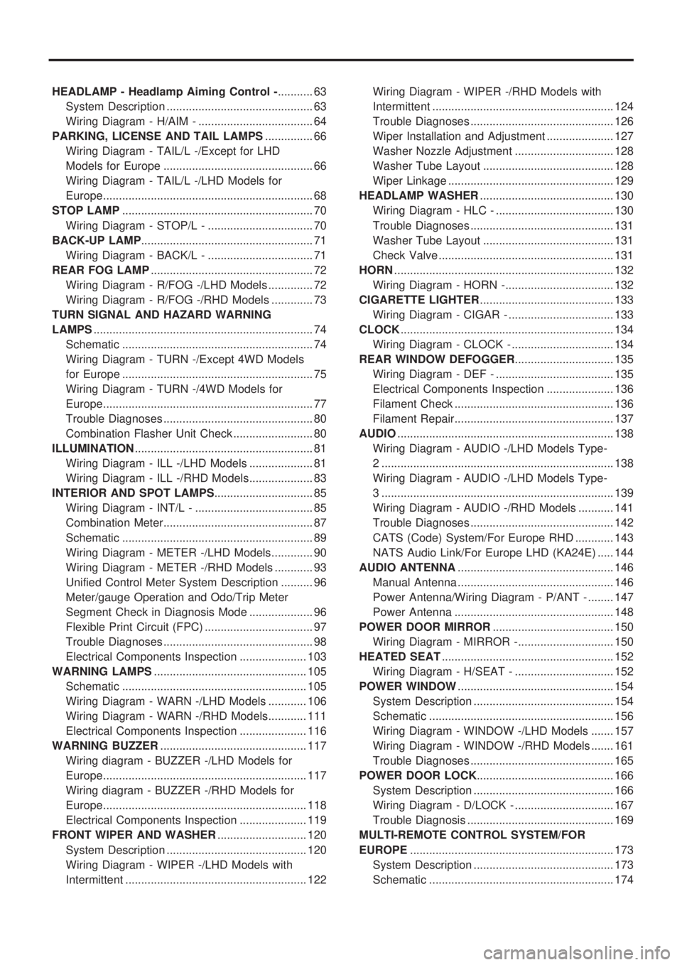
HEADLAMP - Headlamp Aiming Control -........... 63
System Description .............................................. 63
Wiring Diagram - H/AIM - .................................... 64
PARKING, LICENSE AND TAIL LAMPS............... 66
Wiring Diagram - TAIL/L -/Except for LHD
Models for Europe ............................................... 66
Wiring Diagram - TAIL/L -/LHD Models for
Europe.................................................................. 68
STOP LAMP............................................................ 70
Wiring Diagram - STOP/L - ................................. 70
BACK-UP LAMP...................................................... 71
Wiring Diagram - BACK/L - ................................. 71
REAR FOG LAMP................................................... 72
Wiring Diagram - R/FOG -/LHD Models .............. 72
Wiring Diagram - R/FOG -/RHD Models ............. 73
TURN SIGNAL AND HAZARD WARNING
LAMPS..................................................................... 74
Schematic ............................................................ 74
Wiring Diagram - TURN -/Except 4WD Models
for Europe ............................................................ 75
Wiring Diagram - TURN -/4WD Models for
Europe.................................................................. 77
Trouble Diagnoses ............................................... 80
Combination Flasher Unit Check ......................... 80
ILLUMINATION........................................................ 81
Wiring Diagram - ILL -/LHD Models .................... 81
Wiring Diagram - ILL -/RHD Models.................... 83
INTERIOR AND SPOT LAMPS............................... 85
Wiring Diagram - INT/L - ..................................... 85
Combination Meter............................................... 87
Schematic ............................................................ 89
Wiring Diagram - METER -/LHD Models............. 90
Wiring Diagram - METER -/RHD Models ............ 93
Unified Control Meter System Description .......... 96
Meter/gauge Operation and Odo/Trip Meter
Segment Check in Diagnosis Mode .................... 96
Flexible Print Circuit (FPC) .................................. 97
Trouble Diagnoses ............................................... 98
Electrical Components Inspection ..................... 103
WARNING LAMPS................................................ 105
Schematic .......................................................... 105
Wiring Diagram - WARN -/LHD Models ............ 106
Wiring Diagram - WARN -/RHD Models............ 111
Electrical Components Inspection ..................... 116
WARNING BUZZER.............................................. 117
Wiring diagram - BUZZER -/LHD Models for
Europe................................................................ 117
Wiring diagram - BUZZER -/RHD Models for
Europe................................................................ 118
Electrical Components Inspection ..................... 119
FRONT WIPER AND WASHER............................ 120
System Description ............................................ 120
Wiring Diagram - WIPER -/LHD Models with
Intermittent ......................................................... 122Wiring Diagram - WIPER -/RHD Models with
Intermittent ......................................................... 124
Trouble Diagnoses ............................................. 126
Wiper Installation and Adjustment ..................... 127
Washer Nozzle Adjustment ............................... 128
Washer Tube Layout ......................................... 128
Wiper Linkage .................................................... 129
HEADLAMP WASHER.......................................... 130
Wiring Diagram - HLC - ..................................... 130
Trouble Diagnoses ............................................. 131
Washer Tube Layout ......................................... 131
Check Valve ....................................................... 131
HORN..................................................................... 132
Wiring Diagram - HORN -.................................. 132
CIGARETTE LIGHTER.......................................... 133
Wiring Diagram - CIGAR - ................................. 133
CLOCK................................................................... 134
Wiring Diagram - CLOCK - ................................ 134
REAR WINDOW DEFOGGER............................... 135
Wiring Diagram - DEF - ..................................... 135
Electrical Components Inspection ..................... 136
Filament Check .................................................. 136
Filament Repair.................................................. 137
AUDIO.................................................................... 138
Wiring Diagram - AUDIO -/LHD Models Type-
2 ......................................................................... 138
Wiring Diagram - AUDIO -/LHD Models Type-
3 ......................................................................... 139
Wiring Diagram - AUDIO -/RHD Models ........... 141
Trouble Diagnoses ............................................. 142
CATS (Code) System/For Europe RHD ............ 143
NATS Audio Link/For Europe LHD (KA24E) ..... 144
AUDIO ANTENNA................................................. 146
Manual Antenna ................................................. 146
Power Antenna/Wiring Diagram - P/ANT - ........ 147
Power Antenna .................................................. 148
POWER DOOR MIRROR...................................... 150
Wiring Diagram - MIRROR -.............................. 150
HEATED SEAT...................................................... 152
Wiring Diagram - H/SEAT - ............................... 152
POWER WINDOW................................................. 154
System Description ............................................ 154
Schematic .......................................................... 156
Wiring Diagram - WINDOW -/LHD Models ....... 157
Wiring Diagram - WINDOW -/RHD Models ....... 161
Trouble Diagnoses ............................................. 165
POWER DOOR LOCK........................................... 166
System Description ............................................ 166
Wiring Diagram - D/LOCK - ............................... 167
Trouble Diagnosis .............................................. 169
MULTI-REMOTE CONTROL SYSTEM/FOR
EUROPE................................................................ 173
System Description ............................................ 173
Schematic .......................................................... 174
Page 1430 of 1659

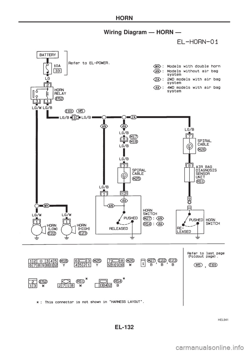
Wiring Diagram Ð HORN Ð
HEL941
HORN
EL-132
Page 1551 of 1659

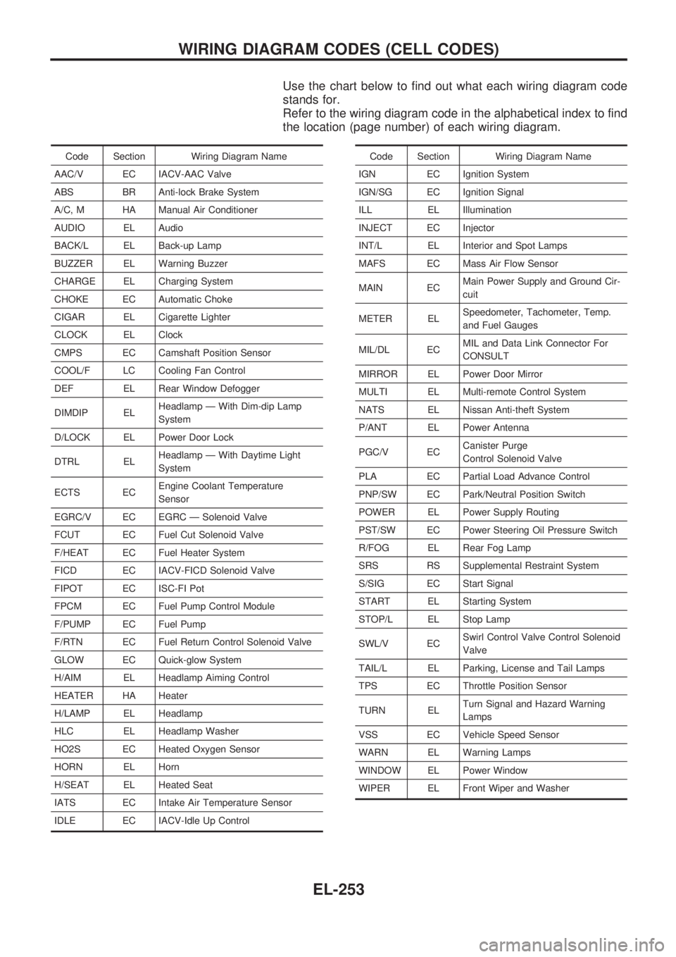
Use the chart below to find out what each wiring diagram code
stands for.
Refer to the wiring diagram code in the alphabetical index to find
the location (page number) of each wiring diagram.
Code Section Wiring Diagram Name
AAC/V EC IACV-AAC Valve
ABS BR Anti-lock Brake System
A/C, M HA Manual Air Conditioner
AUDIO EL Audio
BACK/L EL Back-up Lamp
BUZZER EL Warning Buzzer
CHARGE EL Charging System
CHOKE EC Automatic Choke
CIGAR EL Cigarette Lighter
CLOCK EL Clock
CMPS EC Camshaft Position Sensor
COOL/F LC Cooling Fan Control
DEF EL Rear Window Defogger
DIMDIP ELHeadlamp Ð With Dim-dip Lamp
System
D/LOCK EL Power Door Lock
DTRL ELHeadlamp Ð With Daytime Light
System
ECTS ECEngine Coolant Temperature
Sensor
EGRC/V EC EGRC Ð Solenoid Valve
FCUT EC Fuel Cut Solenoid Valve
F/HEAT EC Fuel Heater System
FICD EC IACV-FICD Solenoid Valve
FIPOT EC ISC-FI Pot
FPCM EC Fuel Pump Control Module
F/PUMP EC Fuel Pump
F/RTN EC Fuel Return Control Solenoid Valve
GLOW EC Quick-glow System
H/AIM EL Headlamp Aiming Control
HEATER HA Heater
H/LAMP EL Headlamp
HLC EL Headlamp Washer
HO2S EC Heated Oxygen Sensor
HORN EL Horn
H/SEAT EL Heated Seat
IATS EC Intake Air Temperature Sensor
IDLE EC IACV-Idle Up ControlCode Section Wiring Diagram Name
IGN EC Ignition System
IGN/SG EC Ignition Signal
ILL EL Illumination
INJECT EC Injector
INT/L EL Interior and Spot Lamps
MAFS EC Mass Air Flow Sensor
MAIN ECMain Power Supply and Ground Cir-
cuit
METER ELSpeedometer, Tachometer, Temp.
and Fuel Gauges
MIL/DL ECMIL and Data Link Connector For
CONSULT
MIRROR EL Power Door Mirror
MULTI EL Multi-remote Control System
NATS EL Nissan Anti-theft System
P/ANT EL Power Antenna
PGC/V ECCanister Purge
Control Solenoid Valve
PLA EC Partial Load Advance Control
PNP/SW EC Park/Neutral Position Switch
POWER EL Power Supply Routing
PST/SW EC Power Steering Oil Pressure Switch
R/FOG EL Rear Fog Lamp
SRS RS Supplemental Restraint System
S/SIG EC Start Signal
START EL Starting System
STOP/L EL Stop Lamp
SWL/V ECSwirl Control Valve Control Solenoid
Valve
TAIL/L EL Parking, License and Tail Lamps
TPS EC Throttle Position Sensor
TURN ELTurn Signal and Hazard Warning
Lamps
VSS EC Vehicle Speed Sensor
WARN EL Warning Lamps
WINDOW EL Power Window
WIPER EL Front Wiper and Washer
WIRING DIAGRAM CODES (CELL CODES)
EL-253