1998 NISSAN PICK-UP wiring diagram
[x] Cancel search: wiring diagramPage 818 of 1659
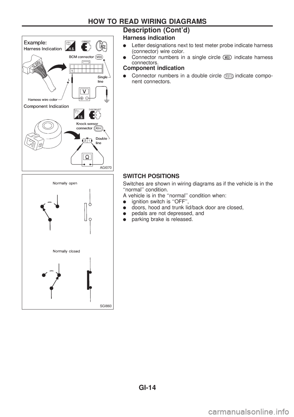
Harness indication
lLetter designations next to test meter probe indicate harness
(connector) wire color.
lConnector numbers in a single circleM33indicate harness
connectors.
Component indication
lConnector numbers in a double circleF211indicate compo-
nent connectors.
SWITCH POSITIONS
Switches are shown in wiring diagrams as if the vehicle is in the
``normal'' condition.
A vehicle is in the ``normal'' condition when:
lignition switch is ``OFF'',
ldoors, hood and trunk lid/back door are closed,
lpedals are not depressed, and
lparking brake is released.
AGI070
SGI860
HOW TO READ WIRING DIAGRAMS
Description (Cont'd)
GI-14
Page 819 of 1659
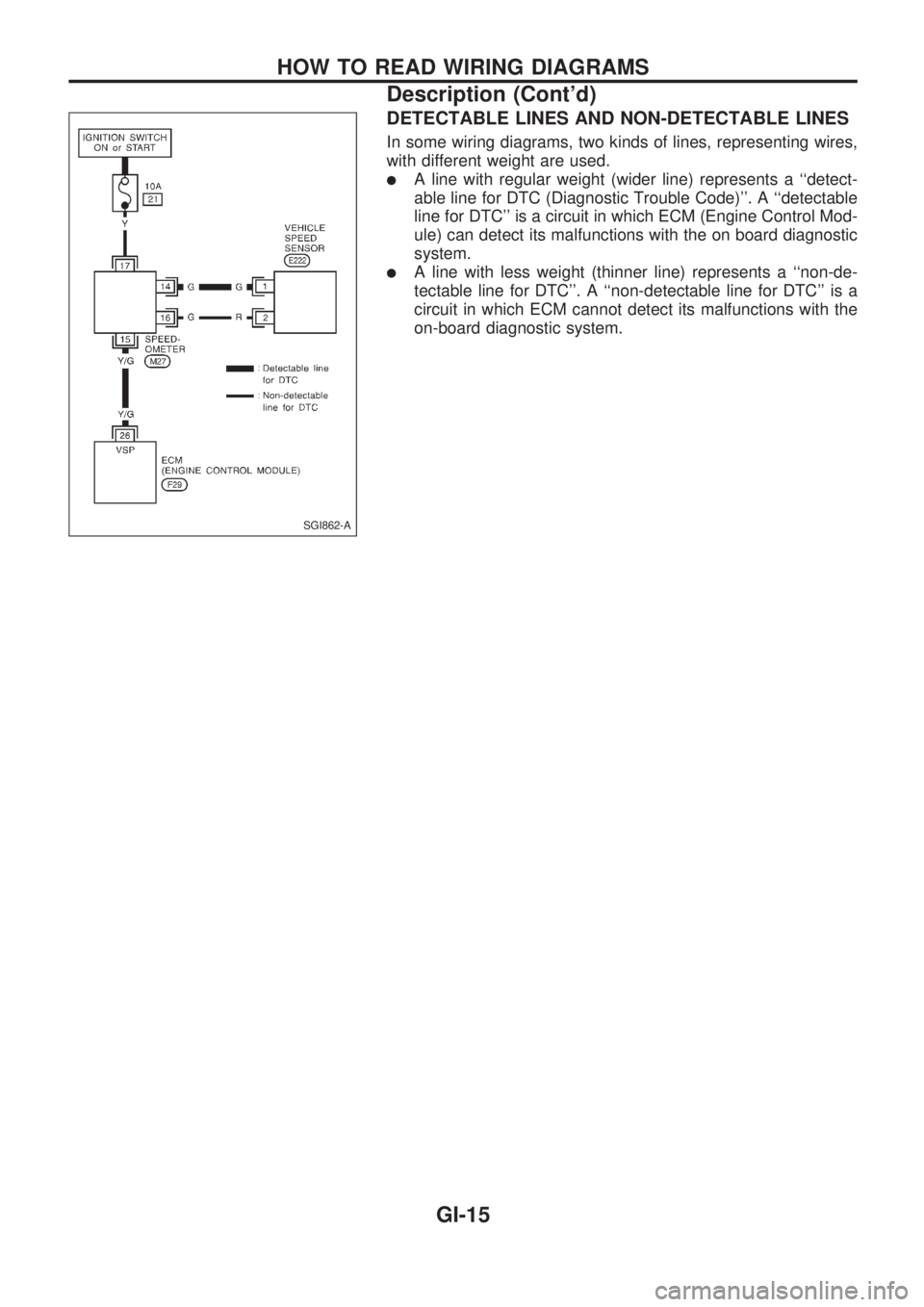
DETECTABLE LINES AND NON-DETECTABLE LINES
In some wiring diagrams, two kinds of lines, representing wires,
with different weight are used.
lA line with regular weight (wider line) represents a ``detect-
able line for DTC (Diagnostic Trouble Code)''. A ``detectable
line for DTC'' is a circuit in which ECM (Engine Control Mod-
ule) can detect its malfunctions with the on board diagnostic
system.
lA line with less weight (thinner line) represents a ``non-de-
tectable line for DTC''. A ``non-detectable line for DTC'' is a
circuit in which ECM cannot detect its malfunctions with the
on-board diagnostic system.
SGI862-A
HOW TO READ WIRING DIAGRAMS
Description (Cont'd)
GI-15
Page 820 of 1659
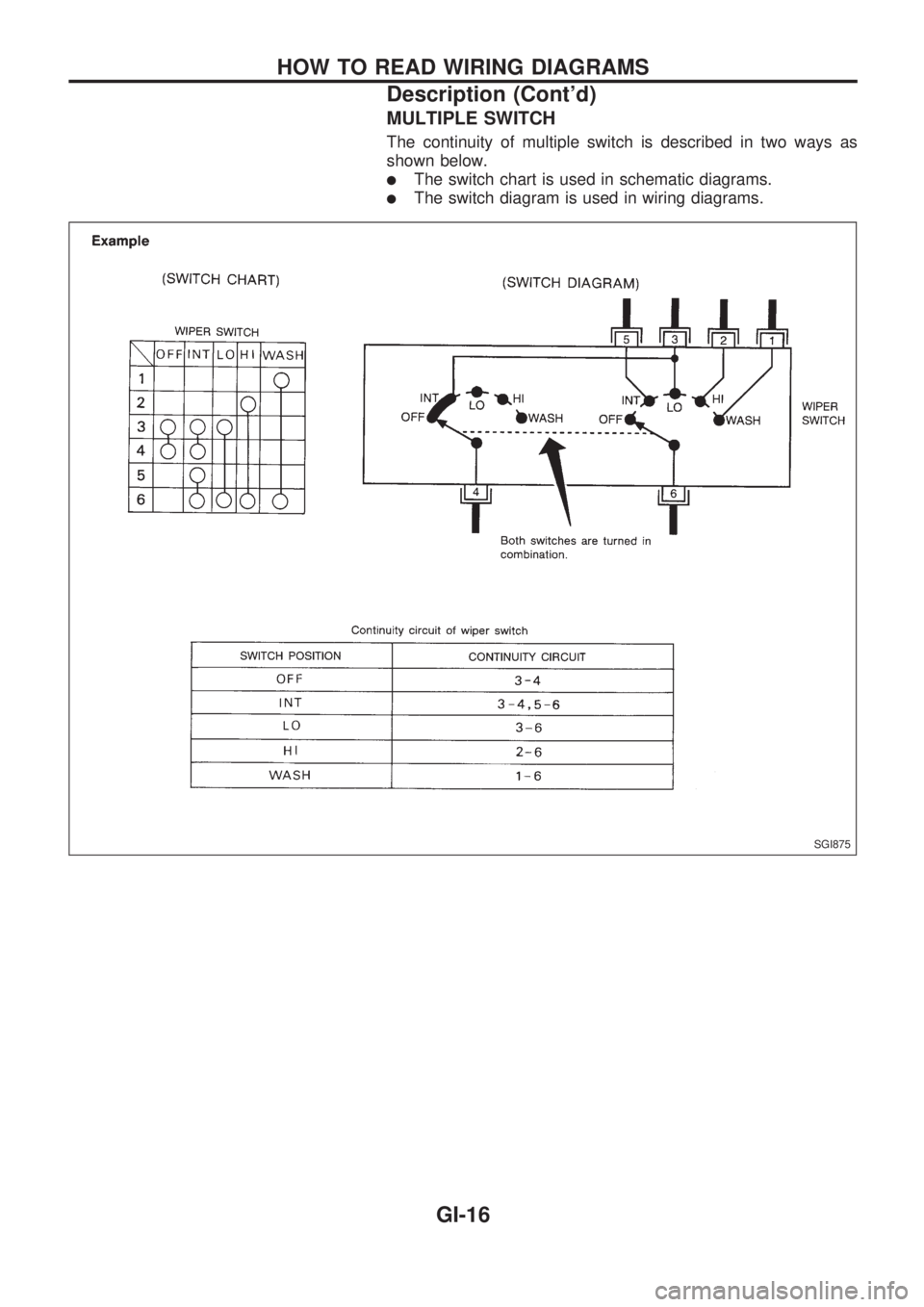
MULTIPLE SWITCH
The continuity of multiple switch is described in two ways as
shown below.
lThe switch chart is used in schematic diagrams.
lThe switch diagram is used in wiring diagrams.
SGI875
HOW TO READ WIRING DIAGRAMS
Description (Cont'd)
GI-16
Page 821 of 1659
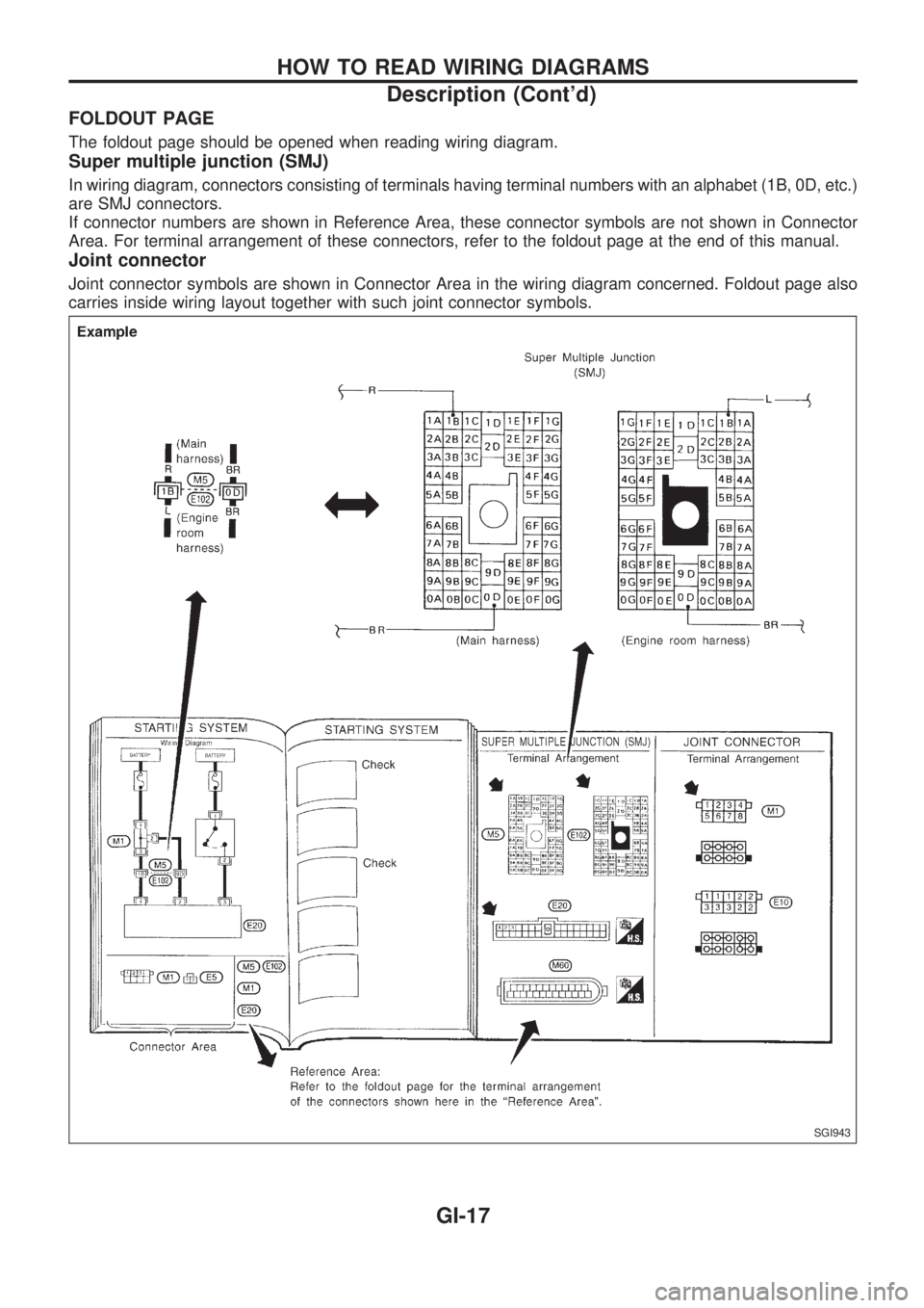
FOLDOUT PAGE
The foldout page should be opened when reading wiring diagram.
Super multiple junction (SMJ)
In wiring diagram, connectors consisting of terminals having terminal numbers with an alphabet (1B, 0D, etc.)
are SMJ connectors.
If connector numbers are shown in Reference Area, these connector symbols are not shown in Connector
Area. For terminal arrangement of these connectors, refer to the foldout page at the end of this manual.
Joint connector
Joint connector symbols are shown in Connector Area in the wiring diagram concerned. Foldout page also
carries inside wiring layout together with such joint connector symbols.
SGI943
HOW TO READ WIRING DIAGRAMS
Description (Cont'd)
GI-17
Page 827 of 1659
Engine compartment
There are several reasons a vehicle or engine vibration could
cause an electrical complaint. Some of the things to check for
are:
lConnectors not fully seated.
lWiring harness not long enough and is being stressed due
to engine vibrations or rocking.
lWires laying across brackets or moving components.
lLoose, dirty or corroded ground wires.
lWires routed too close to hot components.
To inspect components under the hood, start by verifying the
integrity of ground connections. (Refer to GROUND INSPEC-
TION described later.) First check that the system is properly
grounded. Then check for loose connection bygently shaking
the wiring or components as previously explained. Using the
wiring diagrams inspect the wiring for continuity.
Behind the instrument panel
An improperly routed or improperly clamped harness can
become pinched during accessory installation. Vehicle vibration
can aggravate a harness which is routed along a bracket or near
a screw.
Under seating areas
An unclamped or loose harness can cause wiring to be pinched
by seat components (such as slide guides) during vehicle vibra-
tion. If the wiring runs under seating areas, inspect wire routing
for possible damage or pinching.
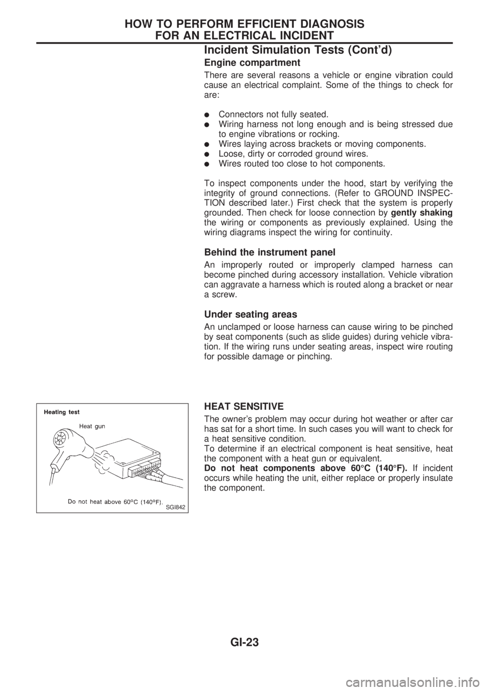
HEAT SENSITIVE
The owner's problem may occur during hot weather or after car
has sat for a short time. In such cases you will want to check for
a heat sensitive condition.
To determine if an electrical component is heat sensitive, heat
the component with a heat gun or equivalent.
Do not heat components above 60ÉC (140ÉF).If incident
occurs while heating the unit, either replace or properly insulate
the component.
SGI842
HOW TO PERFORM EFFICIENT DIAGNOSIS
FOR AN ELECTRICAL INCIDENT
Incident Simulation Tests (Cont'd)
GI-23
Page 835 of 1659
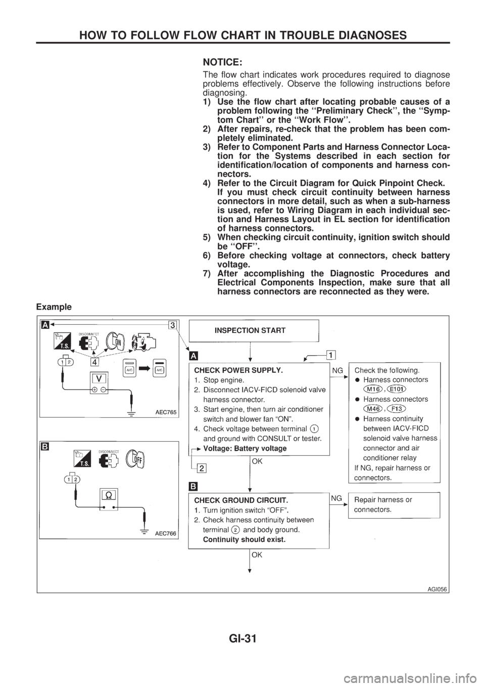
NOTICE:
The flow chart indicates work procedures required to diagnose
problems effectively. Observe the following instructions before
diagnosing.
1) Use the flow chart after locating probable causes of a
problem following the ``Preliminary Check'', the ``Symp-
tom Chart'' or the ``Work Flow''.
2) After repairs, re-check that the problem has been com-
pletely eliminated.
3) Refer to Component Parts and Harness Connector Loca-
tion for the Systems described in each section for
identification/location of components and harness con-
nectors.
4) Refer to the Circuit Diagram for Quick Pinpoint Check.
If you must check circuit continuity between harness
connectors in more detail, such as when a sub-harness
is used, refer to Wiring Diagram in each individual sec-
tion and Harness Layout in EL section for identification
of harness connectors.
5) When checking circuit continuity, ignition switch should
be ``OFF''.
6) Before checking voltage at connectors, check battery
voltage.
7) After accomplishing the Diagnostic Procedures and
Electrical Components Inspection, make sure that all
harness connectors are reconnected as they were.
Example
AGI056
HOW TO FOLLOW FLOW CHART IN TROUBLE DIAGNOSES
GI-31
Page 840 of 1659
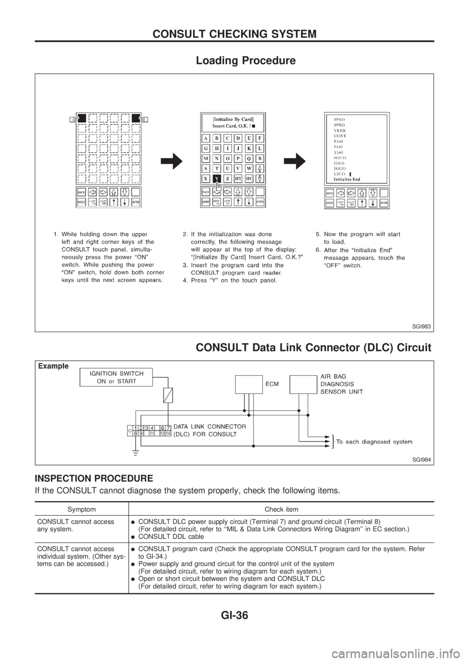
Loading Procedure
CONSULT Data Link Connector (DLC) Circuit
INSPECTION PROCEDURE
If the CONSULT cannot diagnose the system properly, check the following items.
Symptom Check item
CONSULT cannot access
any system.
lCONSULT DLC power supply circuit (Terminal 7) and ground circuit (Terminal 8)
(For detailed circuit, refer to ``MIL & Data Link Connectors Wiring Diagram'' in EC section.)
lCONSULT DDL cable
CONSULT cannot access
individual system. (Other sys-
tems can be accessed.)
lCONSULT program card (Check the appropriate CONSULT program card for the system. Refer
to GI-34.)
lPower supply and ground circuit for the control unit of the system
(For detailed circuit, refer to wiring diagram for each system.)
lOpen or short circuit between the system and CONSULT DLC
(For detailed circuit, refer to wiring diagram for each system.)
SGI983
SGI984
CONSULT CHECKING SYSTEM
GI-36
Page 864 of 1659
A
A/C HFC134a (R134a) system precaution .....HA-2
A/C HFC134a (R134a) system service
procedure ................................................. HA-48
A/C HFC134a (R134a) system service
tools............................................................ HA-8
A/C HFC134a system service
equipment precaution .............................. HA-10
A/C air flow .................................................. HA-14
A/C component layout ................................. HA-13
A/C compressor clutch removal and
installation ................................................ HA-60
A/C compressor precaution ........................... HA-6
A/C compressor special service tool ............. HA-6
A/C control linkage adjustment
(manual A/C) ............................................ HA-45
A/C control operation (manual A/C) ............ HA-16
A/C diagnostic work flow
(manual A/C) ............................................ HA-17
A/C lubricant (R134a) .................................. HA-50
A/C operational check ................................. HA-18
A/C performance chart ................................ HA-26
A/C performance test diagnoses ................. HA-24
A/C relay ...................................................... HA-44
A/C switch.............................................. HA-16, 43
A/C symptom chart (manual A/C) ............... HA-20
A/C trouble diagnoses (manual A/C)........... HA-17
AAC/V - Wiring diagram ............................ EC-133
ABS (anti-lock brake system) ...................... BR-32
ABS - Wiring diagram .................................. BR-42
Accelerator control system............................. FE-1
Accelerator wire adjustment........................... FE-2
Air bag disposal ........................................... RS-14
Air bag precautions ......................................... GI-1
Air bag ........................................................... RS-6
Air bleeding (hydraulic clutch)........................ CL-5
Air bleeding for brake system........................ BR-4
Air cleaner filter replacement
(KA24 engine).......................................... MA-19
Air cleaner filter replacement
(TD25 engine).......................................... MA-29
Air conditioner cut control ............................ EC-18
Air flow meter - See Mass air flow
sensor ...................................................... EC-89
Alternator ...................................................... EL-41
Angular tightening application ....................... EM-1
Antenna ...................................................... EL-146
Anti-lock brake system - Wiring
diagram .................................................... BR-42
Audio and A/C control removal and
installation - See Instrument panel .......... BT-12
Auto-lock free-running hub........................... FA-15
Auxiliary air control (AAC) valve................ EC-131
Axle housing (rear) ........................................ RA-5
B
Back window .................................................BT-24Back-up lamp switch (M/T)............................ MT-9
Ball joint front axle ....................................... FA-34
Battery .......................................................... EL-18
Baulk ring (M/T) (FS5R30A)........................ MT-36
Baulk ring (M/T) (FS5W71C)....................... MT-15
Blower motor................................................ HA-43
Blower resistor ............................................. HA-43
Body alignment ............................................ BT-43
Body mounting ............................................. BT-41
Boring/horning cylinder block ...................... EM-41
Brake booster .............................................. BR-15
Brake fluid change ......................................... BR-3
Brake fluid level and line check..................... BR-3
Brake fluid level ........................................... MA-35
Brake hydraulic line ....................................... BR-5
Brake inspection .......................................... MA-36
Brake lines and cables inspection .............. MA-35
Brake lining wear temporary checking ........ MA-37
Brake master cylinder .................................. BR-12
Brake pedal.................................................. BR-10
Bulb specifications...................................... EL-252
Bumper, front ................................................. BT-5
Bumper, rear .................................................. BT-8
C
CHARGE - Wiring diagram ...........................EL-34
CIGAR - Wiring diagram ............................ EL-133
CLOCK - Wiring diagram ........................... EL-134
CMPS - Wiring diagram............................... EC-85
CONSULT for ECCS ................................... EC-45
CONSULT general information ..................... GI-34
Cab body ...................................................... BT-40
Camshaft inspection (KA24 engine) ........... EM-28
Camshaft inspection (TD25 engine) ........... EM-85
Camshaft position sensor (CMPS) .............. EC-82
Canister - See EVAP canister ..................... EC-19
Center bearing assembly
(propeller shaft) ........................................ PD-10
Center bearing disassembly
(propeller shaft) .......................................... PD-9
Center case (Transfer) ................................... TF-8
Charging system .......................................... EL-34
Chassis and body maintenance .................. MA-32
Cigarette lighter .......................................... EL-133
Circuit breaker .............................................. EL-13
Clock........................................................... EL-134
Clutch cover ................................................. CL-13
Clutch disc.................................................... CL-12
Clutch fluid level .......................................... MA-32
Clutch master cylinder ................................... CL-6
Clutch operating cylinder ............................... CL-8
Clutch pedal ................................................... CL-4
Clutch release bearing ................................... CL-9
Clutch release mechanism............................. CL-9
Clutch withdrawal lever .................................. CL-9
Collision diagnosis (2WD models)............... RS-21
Collision diagnosis (4WD models)............... RS-42
ALPHABETICAL INDEX
IDX-2