h. Install snap ring to 2-4 shift rod.
i. Install speedometer drive gear and oil gutter.
j. Apply gear oil to each part in center case.
9. Apply sealant to mating surface. Set center case assembly onto
front case, then tighten bolts.
10. Install front and rear companion ¯anges and center brake com-
ponents.
SMT107B
SMT106B
SMT171B
ASSEMBLY
TF-32
General Speci®cations
Transfer model TX12A
Gear ratioHigh 1.000
Low 2.020
Number of teethMain gear 29
Low gear 37
Counter
gearHigh 38
Low 24
Front drive sprocket 41
Front drive shaft 41
Fluid capacity liters (Imp qt) 1.9 (1-5/8)
Inspection and Adjustment
GEAR END PLAY
Unit: mm (in)
Front drive sprocket 0.20 - 0.35 (0.0079 - 0.0138)
Low gear 0.20 - 0.35 (0.0079 - 0.0138)
Counter gear 0 - 0.2 (0 - 0.008)
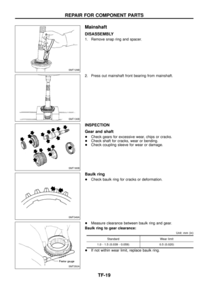
CLEARANCE BETWEEN BAULK RING AND
CLUTCH GEAR
Unit: mm (in)
Standard Wear limit
1.0 - 1.5 (0.039 - 0.059) 0.5 (0.020)
AVAILABLE SNAP RING
Mainshaft front bearing
Unit: mm (in)
Allowable clearance 0 - 0.15 (0 - 0.0059)
Thickness Part number
3.0 (0.118)
3.1 (0.122)
3.2 (0.126)33138-73P10
33138-73P11
33138-73P12
Main gear bearing
Unit: mm (in)
Allowable clearance 0 - 0.15 (0 - 0.0059)
Thickness Part number
2.6 (0.102)
2.7 (0.106)
2.8 (0.110)33114-73P00
33114-73P01
33114-73P02
AVAILABLE SHIM
Counter gear rear bearing
Distance ``A''
mm (in)Shim(s)
Thickness mm (in) Part number
40.6 - 40.5
(1.598 - 1.594)Not necessary
40.5 - 40.4
(1.594 - 1.591)0.1 (0.004) 33112-C6900
40.4 - 40.3
(1.591 - 1.587)0.2 (0.008) 33112-C6901
40.3 - 40.2
(1.587 - 1.583)0.3 (0.012) 33112-C6902
40.2 - 40.1
(1.583 - 1.579)0.4 (0.016) 33112-C6903
40.1 - 40.0
(1.579 - 1.575)0.5 (0.020) 33112-33G00
40.0 - 39.9
(1.575 - 1.571)0.6 (0.024) 33112-33G01
SMT335A
SERVICE DATA AND SPECIFICATIONS (SDS)
TF-33