Page 17 of 34
13. Remove bolts securing center case to front case and then
separate center case and front case.
14. Measure end play of low gear.
Standard:
0.20 - 0.35 mm (0.0079 - 0.0138 in)
Refer to SDS, TF-33.
+If end play is beyond the maximum value, check low gear and
L & H hub for wear.
15. Disassemble center case assembly.
a. Remove snap ring from mainshaft.
b. Pull out low gear with L & H hub.
c. Remove mainshaft by tapping front end of mainshaft.
SMT116B
SMT117B
SMT118B
SMT119B
SMT120B
DISASSEMBLY
TF-16
Page 18 of 34
16. Disassemble front case assembly.
a. Remove the following parts.
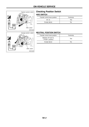
+4WD switch
+Neutral position switch
+Check plugs
+Check springs
+Check balls
+Be careful not to lose the check balls.
b. Remove 2-4 shift rod.
c. Remove L & H shift rod and fork assembly with coupling sleeve.
d. Remove needle bearing from main gear.
e. Remove bolts securing front case cover and then remove it.
SMT259D
SMT122B
SMT260D
SMT124B
SMT125B
DISASSEMBLY
TF-17
Page 19 of 34
f. Remove counter gear by tapping it lightly with a soft hammer.
g. Remove main gear by tapping it lightly with a soft hammer.
SMT261D
SMT262D
DISASSEMBLY
TF-18
Page 20 of 34
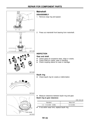
Mainshaft
DISASSEMBLY
1. Remove snap ring and spacer.
2. Press out mainshaft front bearing from mainshaft.
INSPECTION
Gear and shaft
+Check gears for excessive wear, chips or cracks.
+Check shaft for cracks, wear or bending.
+Check coupling sleeve for wear or damage.
Baulk ring
+Check baulk ring for cracks or deformation.
+Measure clearance between baulk ring and gear.
Baulk ring to gear clearance:
Unit: mm (in)
Standard Wear limit
1.0 - 1.5 (0.039 - 0.059) 0.5 (0.020)
+If not within wear limit, replace baulk ring.
SMT129B
SMT130B
SMT180B
SMT349A
SMT350A
REPAIR FOR COMPONENT PARTS
TF-19
Page 21 of 34
Bearing
+Make sure bearings roll freely and are free from noise, crack,
pitting or wear.
ASSEMBLY
1. Press mainshaft front bearing onto mainshaft.
+Pay special attention to its direction.
2. Install spacer.
3. Select mainshaft front bearing snap ring with proper thickness
and install it.
Allowable clearance between mainshaft front bearing
snap ring and groove:
0 - 0.15 mm (0 - 0.0059 in)
Mainshaft front bearing snap ring:
Refer to SDS, TF-33.
Front Drive Shaft
DISASSEMBLY
+Front drive shaft front bearing
+Front drive shaft rear bearing
SMT351A
SMT294A
SMT295A
SMT296A
SMT297A
REPAIR FOR COMPONENT PARTS
Mainshaft (Cont'd)
TF-20
Page 22 of 34
INSPECTION
Sprocket and shaft
+Check sprocket for excessive wear, chips or cracks.
+Check shaft for cracks or wear.
Bearing
+Make sure bearings roll freely and are free from noise, crack,
pitting or wear.
ASSEMBLY
+Press front drive shaft front bearing.
+Press front drive shaft rear bearing.
Counter Gear
DISASSEMBLY
1. Press out counter gear front bearing and then remove front
sub-gear, spacer and dish spring.
2. Press out counter gear rear bearing and then remove rear
sub-gear, spacer and dish spring.
SMT357A
SMT298A
SMT299A
SMT134B
SMT135B
REPAIR FOR COMPONENT PARTS
Front Drive Shaft (Cont'd)
TF-21
Page 23 of 34
INSPECTION
Gear and shaft
+Check gears for excessive wear, chips or cracks.
+Check shaft for cracks or wear.
Bearing
+Make sure bearings roll freely and are free from noise, crack,
pitting or wear.
ASSEMBLY
1. Press on counter gear rear bearing.
2. Install front sub-gear, dish spring and spacer, and then press on
counter gear front bearing.
+Pay attention to direction of dish spring.
Main Gear
DISASSEMBLY
Main gear bearing
1. Remove snap ring and spacer.
2. Pull out main gear bearing.
SMT266D
SMT267D
SMT137B
SMT304A
SMT305AA
REPAIR FOR COMPONENT PARTS
Counter Gear (Cont'd)
TF-22
Page 24 of 34
Plug
+Always replace it with new one whenever it is removed.
INSPECTION
Gear and shaft
+Check gears for excessive wear, chips or cracks.
+Check shaft for cracks or wear.
Bearing
+Make sure bearings roll freely and are free from noise, crack,
pitting or wear.
ASSEMBLY
Main gear bearing
1. Press on main gear bearing.
+Pay attention to its direction.
2. Install spacer.
3. Select snap ring with proper thickness and install it.
Allowable clearance between snap ring and groove:
0 - 0.15 mm (0 - 0.0059 in)
Snap ring (main gear bearing):
Refer to SDS, TF-33.
Plug
+Apply sealant to plug and install it.
SMT306A
SMT359A
SMT307AA
SMT308A
SMT309A
REPAIR FOR COMPONENT PARTS
Main Gear (Cont'd)
TF-23


Refer to SDS, TF-33.
+")


