Page 17 of 47

Installation Ð Air Bag Module and Spiral Cable
1. Set the front wheels in the straight-ahead position.
2. Make sure that the spiral cable is in the neutral position. The
neutral position is detected by turning left about 2.5 revolutions
from the right end position. Align the two marks (
,
m).
CAUTION:
+The spiral cable may snap due to steering operation if the
cable is installed in an improper position.
+Also, with the steering linkage disconnected, the cable
may snap by turning the steering wheel beyond the limited
number of turns. The spiral cable can be turned to the left
about 2.5 turns from the right end position.
3. Connect and lock spiral cable connector and tighten with
screws. Install steering column cover.
4. Install steering wheel, aligning with spiral cable pin guides, and
pull spiral cable through.
5. Connect horn connector and engage spiral cable with pawls in
steering wheel. Move air bag module connector away from
steering wheel lower lid opening.
6. Tighten nut.
:29-39Nzm (3.0 - 4.0 kg-m, 22 - 29 ft-lb)
7. Position air bag module and tighten with new special bolts.
8. Connect air bag module connector.
9. Install all lids.
10. Conduct self-diagnosis to ensure entire SRS operates properly.
(Use CONSULT or warning lamp check.)
Before performing self-diagnosis, connect both battery cables.
11. Turn steering wheel to the left end and then to the right end fully
to make sure that spiral cable is set in the neutral position.
If air bag warning lamp blinks or stays ON (at the User mode),
it shows the spiral cable may be snapped due to its improper
position. Perform self-diagnosis again (use CONSULT or warn-
ing lamp). If a malfunction is detected, replace the spiral cable
with a new one.
12. Perform self-diagnosis again to check that no malfunction is
detected.
Installation Ð Front Passenger Air Bag Module
+Always work from the side of air bag module.
1. Install front passenger air bag module on steering member.
+Ensure harness is not caught between rear of air bag module
and steering member.
2. Connect in¯ator connector to body harness connector.
3. Install in¯ator connector on steering member.
SRS276
SRS166
SBF812EB
SRS457
SUPPLEMENTAL RESTRAINT SYSTEM (SRS)
RS-16
Page 18 of 47

5. Close the glove box lid.
Disposal of Air Bag Module and Seat Belt Pre-
tensioner
+Before disposing of air bag module and seat belt pre-tensio")
4. Install glove box assembly. (Glove box lid is open.)
5. Close the glove box lid.
Disposal of Air Bag Module and Seat Belt Pre-
tensioner
+Before disposing of air bag module and seat belt pre-tensioner, or vehicles equipped with such systems,
deploy the systems. If such systems have already been deployed due to an accident, dispose of as indi-
cated in ``DISPOSING OF AIR BAG MODULE AND SEAT BELT PRE-TENSIONER'' (RS-21).
+When deploying the air bag module, always use the Special Service Tool; Deployment tool KV99106400,
KV99108200 and KV99108300.
+When deploying the air bag module and seat belt pre-tensioner, stand at least 5 m (16 ft) away from the
deployment component.
+When deploying air bag module and seat belt pre-tensioner, a fairly loud noise is made, followed by smoke
being released. The smoke is not poisonous, however, be careful not to inhale smoke since it irritates throat
and can cause choking.
+Always activate one air bag module at a time.
+Due to heat, leave air bag module unattended for more than 30 minutes after deployment. Also leave seat
belt pre-tensioner unattended for more than 10 minutes after deployment.
+Be sure to wear gloves when handling a deployed air bag module.
+Never apply water to a deployed air bag module.
+Wash your hands clean after ®nishing work.
+Do not dispose of the air bag module un-deployed.
+Place the vehicle outdoors with an open space of at least 6 m (20 ft) on all sides when deploying the air
bag module while mounted in vehicle.
+Use a voltmeter to make sure the vehicle battery is fully charged.
CHECKING DEPLOYMENT TOOL
Connecting to battery
CAUTION:
The battery must show voltage of 9.6V or more.
Remove the battery from the vehicle and place it on dry wood
blocks approximately 5 m (16 ft) away from the vehicle.
+Wait 3 minutes after the vehicle battery is disconnected before
proceeding.
+Connect red clip of deployment tool to battery positive terminal
and black clip to negative terminal.
Make sure the polarity is correct. The right side lamp in the
tool, marked ``deployment tool power'', should glow with a
green light. If the right side lamp glows red, reverse the con-
nections to the battery.
SRS456
SRS005-B
SUPPLEMENTAL RESTRAINT SYSTEM (SRS)
Installation Ð Front Passenger Air Bag Module
(Cont'd)
RS-17
Page 19 of 47

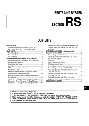
Deployment tool check
Press the deployment tool switch to the ``ON'' position. The left side
lamp in the tool, marked ``air bag connector voltage'' should illumi-
nate. If it does not illuminate, replace the tool.
Air bag deployment tool lamp illumination chart
(Battery connected)
Switch operationLeft side lamp, green*
``AIR BAG CONNECTOR
VOLTAGE''Right side lamp, green*
``DEPLOYMENT TOOL
POWER''
OFF OFF ON
ON ON ON
*: If this lamp glows red, the tool is connected to the battery incorrectly.
Reverse the connections and make sure the lamp glows green.
DEPLOYMENT PROCEDURES FOR AIR BAG MODULE
(OUTSIDE OF VEHICLE)
Unless the vehicle is being scrapped, deploying the air bag in the
vehicle is not recommended. This may cause damage to the
vehicle interior.
Anchor air bag module in a vise secured to a ®rm foundation dur-
ing deployment.
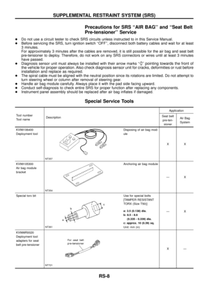
Deployment of driver's air bag module (outside of
vehicle)
1. Using wire, secure air bag module to air bag module bracket
(SST: KV99105300).
CAUTION:
Use wire of at least 1 mm (0.04 in) diameter.
2. Firmly secure air bag module bracket (SST: KV99105300) with
air bag module attached, in a vise.
3. Connect deployment tool (SST: KV99106400) to air bag mod-
ule connector.
SBF266H
SRS232-B
SRS233-B
SRS234-B
SUPPLEMENTAL RESTRAINT SYSTEM (SRS)
Disposal of Air Bag Module and Seat Belt Pre-
tensioner (Cont'd)
RS-18
Page 20 of 47

4. Connect red clip of deployment tool to battery positive terminal
and black clip to negative terminal.
5. The lamp on the right side of the tool, marked ``deployment tool
power'', should glow green, not red.
6. Press the button on the deployment tool. The left side lamp on
the tool, marked ``air bag connector voltage'', will illuminate and
the air bag module will deploy.
CAUTION:
When deploying the air bag module, stand at least 5 m (16 ft)
away from the air bag module.
Deployment of passenger air bag module (outside of
vehicle)
1. Make an 8.5 mm (0.335 in) diameter hole in air bag module
bracket (SST: KV99105300) at the position shown in ®gure at
left.
2. Firmly secure air bag module bracket (SST: KV99105300) in a
vise.
3. Match the two holes in air bag module bracket (held in vise) and
passenger air bag module and ®x them with two bolts [M8 x 25
- 30 mm (0.98 - 1.18 in)].
CAUTION:
If a gap exists between passenger air bag module and air bag
module bracket, use a piece of wood inserted in the gap to
stabilize the air bag module.
4. Connect deployment tool adapter (SST: KV99108300) to
deployment tool (SST: KV99106400) connector and connector
on either side of air bag module.
5. Connect red clip of deployment tool to battery positive terminal
and black clip to negative terminal.
6. The lamp on the right side of the tool, marked ``deployment tool
power'', should glow green, not red.
7. Press the button on the deployment tool. The left side lamp on
the tool, marked ``air bag connector voltage'', will illuminate and
the air bag module will deploy.
SRS235-B
SRS236-B
SRS310
SRS311
SRS313-A
SUPPLEMENTAL RESTRAINT SYSTEM (SRS)
Disposal of Air Bag Module and Seat Belt Pre-
tensioner (Cont'd)
RS-19
Page 21 of 47
 away from the air bag module.
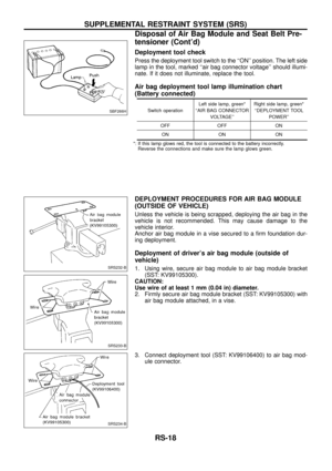
Deployment of seat belt pre-tensioner (outside of
vehicle)
1.")
CAUTION:
+When deploying the air bag module, do not stand on the
deploying side.
+Stand at least 5 m (16 ft) away from the air bag module.
Deployment of seat belt pre-tensioner (outside of
vehicle)
1. Firmly anchor seat belt pre-tensioner in a vise.
CAUTION:
Ensure bracket and webbing are placed in the vise.
2. Connect deployment tool adapter (SST: KV999R0020) to
deployment tool (SST: KV99106400) connector and seat belt
pre-tensioner connector.
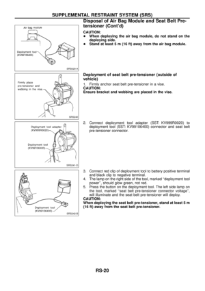
3. Connect red clip of deployment tool to battery positive terminal
and black clip to negative terminal.
4. The lamp on the right side of the tool, marked ``deployment tool
power'', should glow green, not red.
5. Press the button on the deployment tool. The left side lamp on
the tool, marked ``seat belt pre-tensioner connector voltage'',
will illuminate and the seat belt pre-tensioner will deploy.
CAUTION:
When deploying the seat belt pre-tensioner, stand at least 5 m
(16 ft) away from the seat belt pre-tensioner.
SRS020-A
SRS240
SRS241-D
SRS242-B
SUPPLEMENTAL RESTRAINT SYSTEM (SRS)
Disposal of Air Bag Module and Seat Belt Pre-
tensioner (Cont'd)
RS-20
Page 22 of 47

DEPLOYMENT OF AIR BAG MODULE AND SEAT BELT
PRE-TENSIONER WHILE MOUNTED IN VEHICLE
When disposing of a vehicle, deploy air bag modules and seat belt
pre-tensioners while they are mounted in vehicle.
CAUTION:
When deploying air bag module or seat belt pre-tensioner,
ensure vehicle is empty.
1. Disconnect both the vehicle battery cables and wait 3 minutes.
2. Disconnect air bag modules and seat belt pre-tensioners con-
nector.
3. Connect deployment tool (SST: KV99106400) to air bag mod-
ule or seat belt pre-tensioner.
For front passenger air bag module and seat belt pre-tensioner,
attach deployment tool adapter (SST: KV99108300 and
KV999R0020) to the tool connector.
4. Connect red clip of deployment tool to battery positive terminal
and black clip to negative terminal.
5. The lamp on the right side of the tool, marked ``deployment tool
power'', should glow green, not red.
6. Press the button on the deployment tool. The left side lamp on
the tool, marked ``air bag connector voltage'', will illuminate and
the air bag module or seat belt pre-tensioner will deploy.
CAUTION:
Activate only one passenger air bag module or seat belt pre-
tensioner at a time.
DISPOSING OF AIR BAG MODULE AND SEAT BELT
PRE-TENSIONER
Deployed air bag modules and seat belt pre-tensioners are very
hot. Before disposing of air bag module, and seat belt pre-
tensioner, wait at least 30 minutes, and 10 minutes, respectively.
Seal them in a plastic bag before disposal.
CAUTION:
+Never apply water to a deployed air bag module and seat
belt pre-tensioner.
+Be sure to wear gloves when handling a deployed air bag
module and seat belt pre-tensioner.
+No poisonous gas is produced upon air bag module
deployment. However, be careful not to inhale gas since it
irritates throat and can cause choking.
+Do not attempt to disassemble air bag module and seat
belt pre-tensioner.
+Air bag module and seat belt pre-tensioner cannot be re-
used.
+Wash your hands clean after ®nishing work.
SRS006-D
SBF276H
SUPPLEMENTAL RESTRAINT SYSTEM (SRS)
Disposal of Air Bag Module and Seat Belt Pre-
tensioner (Cont'd)
RS-21
Page 23 of 47

Trouble Diagnoses Introduction
CAUTION:
+Do not use a circuit tester to check SRS harness connectors unless instructed to in this Service
Manual. SRS wiring harnesses except for ``SEAT BELT PRE-TENSIONER'' can be identi®ed with
yellow harness protector or yellow insulation tape before the harness connectors.
+Do not attempt to repair, splice or modify the SRS wiring harness. If the harness is damaged,
replace it with a new one.
+Keep ground portion clean.
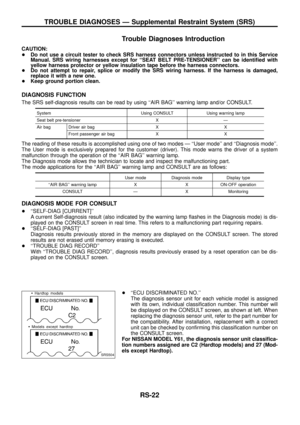
DIAGNOSIS FUNCTION
The SRS self-diagnosis results can be read by using ``AIR BAG'' warning lamp and/or CONSULT.
System Using CONSULT Using warning lamp
Seat belt pre-tensioner X Ð
Air bag Driver air bag X X
Front passenger air bag X X
The reading of these results is accomplished using one of two modes Ð ``User mode'' and ``Diagnosis mode''.
The User mode is exclusively prepared for the customer (driver). This mode warns the driver of a system
malfunction through the operation of the ``AIR BAG'' warning lamp.
The Diagnosis mode allows the technician to locate and inspect the malfunctioning part.
The mode applications for the ``AIR BAG'' warning lamp and CONSULT are as follows:
User mode Diagnosis mode Display type
``AIR BAG'' warning lamp X X ON-OFF operation
CONSULT Ð X Monitoring
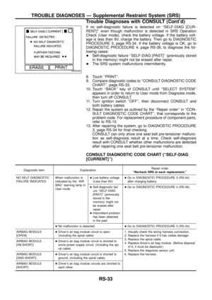
DIAGNOSIS MODE FOR CONSULT
+``SELF-DIAG [CURRENT]''
A current Self-diagnosis result (also indicated by the warning lamp ¯ashes in the Diagnosis mode) is dis-
played on the CONSULT screen in real time. This refers to a malfunctioning part requiring repairs.
+``SELF-DIAG [PAST]''
Diagnosis results previously stored in the memory are displayed on the CONSULT screen. The stored
results are not erased until memory erasing is executed.
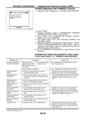
+``TROUBLE DIAG RECORD''
With ``TROUBLE DIAG RECORD'', diagnosis results previously erased by a reset operation can be dis-
played on the CONSULT screen.
+``ECU DISCRIMINATED NO.''
The diagnosis sensor unit for each vehicle model is assigned
with its own, individual classi®cation number. This number will
be displayed on the CONSULT screen, as shown at left. When
replacing the diagnosis sensor unit, refer to the part number for
the compatibility. After installation, replacement with a correct
unit can be checked by con®rming this classi®cation number on
the CONSULT screen.
For NISSAN MODEL Y61, the diagnosis sensor unit classi®ca-
tion numbers assigned are C2 (Hardtop models) and 27 (Mod-
els except Hardtop).
SRS504
TROUBLE DIAGNOSES Ð Supplemental Restraint System (SRS)
RS-22
Page 24 of 47

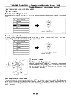
HOW TO CHANGE SELF-DIAGNOSIS MODE
With CONSULT
From User mode to Diagnosis mode
After selecting AIR BAG on the ``SELECT SYSTEM'' screen, User mode automatically changes to Diagnosis
mode.
From Diagnosis mode to User mode
To return to User mode from diagnosis mode, touch ``BACK'' key of CONSULT until ``SELECT SYSTEM''
appears. Diagnosis mode automatically changes to User mode.
Without CONSULT
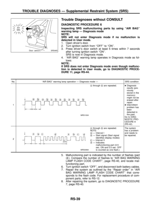
From User mode to Diagnosis mode
Diagnosis mode activates only when a malfunction is detected, by
pressing the driver's door switch at least 5 times within 7 seconds
after turning the ignition ``ON''. SRS will not enter Diagnosis mode
if no malfunction is detected.
From Diagnosis mode to User mode
After a malfunction is repaired, switch the ignition ``OFF'' for at least 1 second, then back ``ON''. Diagnosis
mode returns to User mode. If switching from Diagnosis mode to User mode is required while malfunction is
being detected, switch the ignition ``OFF'', then back ``ON'' and press the driver's door switch at least 5 times
within 7 seconds.
SRS391
SRS392
SRS465
TROUBLE DIAGNOSES Ð Supplemental Restraint System (SRS)
Trouble Diagnoses Introduction (Cont'd)
RS-23