Page 9 of 47

Precautions for SRS ``AIR BAG'' and ``Seat Belt
Pre-tensioner'' Service
+Do not use a circuit tester to check SRS circuits unless instructed to in this Service Manual.
+Before servicing the SRS, turn ignition switch ``OFF'', disconnect both battery cables and wait for at least
3 minutes.
For approximately 3 minutes after the cables are removed, it is still possible for the air bag and seat belt
pre-tensioner to deploy. Therefore, do not work on any SRS connectors or wires until at least 3 minutes
have passed.
+Diagnosis sensor unit must always be installed with their arrow marks ``
S'' pointing towards the front of
the vehicle for proper operation. Also check diagnosis sensor unit for cracks, deformities or rust before
installation and replace as required.
+The spiral cable must be aligned with the neutral position since its rotations are limited. Do not attempt to
turn steering wheel or column after removal of steering gear.
+Handle air bag module carefully. Always place it with the pad side facing upward.
+Conduct self-diagnosis to check entire SRS for proper function after replacing any components.
+Instrument panel assembly should be replaced after air bag in¯ates if damaged.
Special Service Tools
Tool number
Tool nameDescriptionApplication
Seat belt
pre-ten-
sionerAir Bag
System
KV99106400
Deployment tool
NT357
Disposing of air bag mod-
ule
XX
KV99105300
Air bag module
bracket
NT354
Anchoring air bag module
ÐX
Special torx bit
NT361
Use for special bolts
[TAMPER RESISTANT
TORX (Size T50)]
a: 3.5 (0.138) dia.
b: 8.5 - 8.6
(0.335 - 0.339) dia.
c: approx. 10 (0.39) sq.
Unit: mm (in)ÐX
KV999R0020
Deployment tool
adapters for seat
belt pre-tensioner
NT721
XÐ
SUPPLEMENTAL RESTRAINT SYSTEM (SRS)
RS-8
Page 10 of 47
Tool number
Tool nameDescriptionApplication
Seat belt
pre-ten-
sionerAir Bag
System
KV99108300
Deployment tool
adapters for pas-
senger air bag
NT722
ÐX
SUPPLEMENTAL RESTRAINT SYSTEM (SRS)
Special Service Tools (Cont'd)
RS-9
Page 11 of 47
Description
The air bag deploys if the diagnosis sensor unit activates while the ignition switch is in the ``ON'' or ``START''
position.
SRS Component Parts Location
SBF564HA
SRS452
SUPPLEMENTAL RESTRAINT SYSTEM (SRS)
RS-10
Page 12 of 47

Maintenance Items
CAUTION:
Do not use a circuit tester to check SRS circuit.
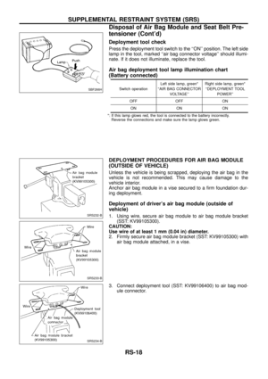
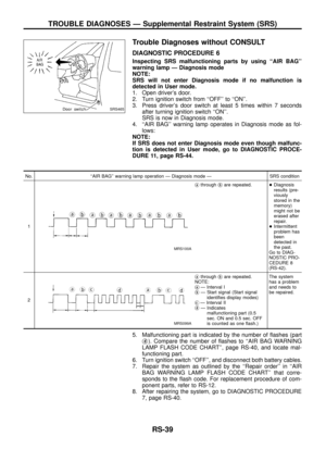
1. Check operation of ``AIR BAG'' warning lamp.
After turning ignition key to ``ON'' position, both warning lamps
illuminate. The ``AIR BAG'' warning lamp will go off after about
7 seconds if no malfunction is detected.
If any of the following warning lamp conditions occur, immedi-
ately check the air bag or seat belt pre-tensioner system. Refer
to RS-30 for details.
+The ``AIR BAG'' warning lamp does not illuminate when the
ignition switch is turned ``ON''.
+The ``AIR BAG'' warning lamp does not go off about 7 seconds
after the ignition switch is turned ``ON''.
+The ``AIR BAG'' warning lamp blinks about 7 seconds after the
ignition switch is turned ``ON''.
2. Visually check SRS components.
(1) Diagnosis sensor unit
+Check diagnosis sensor unit and bracket for dents, cracks or
deformities.
+Check connectors for damage, and terminals for deformities.
(2) Air bag module and steering wheel
+Remove air bag module from steering wheel or instrument
panel. Check harness cover and connectors for damage, ter-
minals for deformities, and harness for binding.
+Install driver air bag module to steering wheel to check ®t or
alignment with the wheel.
+Check steering wheel for excessive free play.
+For dual air bag system, install passenger air bag module to
instrument panel to check ®t or alignment with the instrument
panel.
(3) Spiral cable
+Check spiral cable for dents, cracks, or deformities.
+Check connectors and protective tape for damage.
+Check steering wheel for noise, binding or heavy operation.
(4) Harness related to SRS
+Check connectors for poor connections, damage, and terminals
for deformities.
+Check harnesses for binding, cha®ng or cut.
(5) Seat belt pre-tensioner
+Check harness cover and connectors for damage, terminals for
deformities, and harness for binding.
+Check belts for damage and anchors for loose mounting.
+Check retractor for smooth operation.
+Perform self-diagnosis for seat belt pre-tensioner using
bulb or CONSULT. Refer to ``SRS Operation Check'' for details.
(RS-30)
CAUTION:
Replace previously used special bolts, ground bolt and anchor
bolt with new ones.
SRS451
SUPPLEMENTAL RESTRAINT SYSTEM (SRS)
RS-11
Page 13 of 47

Removal and Installation Ð Diagnosis Sensor
Unit and Seat Belt Pre-tensioner
CAUTION:
+Before servicing SRS, turn the ignition switch off, disconnect both battery cables and wait for at
least 3 minutes.
+The special bolts are coated with bonding agent while the other bolt is for ground. Do not use old
bolts after removal; replace with new ones.
+Check diagnosis sensor unit and seat belt pre-tensioner for proper installation.
+Check diagnosis sensor unit to ensure they are free of deformities, dents, cracks or rust. If they
show any visible signs of damage, replace them with new ones.
+Check diagnosis sensor unit brackets to ensure they are free of deformities or rust.
+Replace diagnosis sensor unit and seat belt pre-tensioner if they have been dropped or sustained
an impact.
+After replacement of diagnosis sensor unit and seat belt pre-tensioner, check SRS function and
perform self-diagnosis for SRS. Refer to ``SRS Operation Check'' for details (RS-30).
+Do not attempt to disassemble diagnosis sensor unit and seat belt pre-tensioner.
+Do not expose seat belt pre-tensioner to temperatures exceeding 80ÉC (176ÉF).
REMOVAL OF DIAGNOSIS SENSOR UNIT
1. Disconnect driver and passenger air bag module connectors.
Also, disconnect seat belt pre-tensioner connector.
2. Remove console ®nisher, console box assembly and instru-
ment panel stay cover. Refer to ``INSTRUMENT PANEL'' in BT
section.
3. Remove rear heater duct and foot duct. (If equipped with rear
heater duct and foot duct.)
4. Remove bolt and also remove special bolts using the TAMPER
RESISTANT TORX (Size T50), from diagnosis sensor unit.
5. Disconnect diagnosis sensor unit connector. Then remove the
diagnosis sensor unit.
NOTE:
+To install, reverse the removal procedure sequence.
REMOVAL OF SEAT BELT PRE-TENSIONER
For removal of seat belt pre-tensioner, refer to ``Front Seat Belt'' for
details. (RS-3)
NOTE:
+To install, reverse the removal procedure sequence.
SRS453
SRS454
SUPPLEMENTAL RESTRAINT SYSTEM (SRS)
RS-12
Page 14 of 47
Removal and Installation Ð Air Bag Module
and Spiral Cable
Removal Ð Air Bag Module and Spiral Cable
CAUTION:
+Before servicing SRS, turn the ignition switch off, discon-
nect both battery cables and wait for at least 3 minutes.
+Always work from the side of air bag module.
1. Remove lower lid from steering wheel, and disconnect air bag
module connector.
2. Remove side lids. Using the TAMPER RESISTANT TORX (Size
T50), remove left and right special bolts. Air bag module can
then be removed.
SRS455
SBF811E
SBF812E
SUPPLEMENTAL RESTRAINT SYSTEM (SRS)
RS-13
Page 15 of 47

CAUTION:
+Always place air bag module with pad side facing upward.
+Do not attempt to disassemble air bag module.
+The special bolts are coated with bonding agent. Do not
use old bolts after removal; replace with new ones.
+Replace air bag module if it has been dropped or sustained
an impact.
+Do not expose the air bag module to temperatures exceed-
ing 90ÉC (194ÉF).
+Do not allow oil, grease or water to come in contact with
the air bag module.
3. Set steering wheel in the neutral position.
4. Disconnect horn connector and remove nuts.
5. Using steering wheel puller, remove steering wheel. Be careful
not to over-tighten puller bolt on steering wheel.
CAUTION:
Do not tap or bump the steering wheel.
6. Remove steering column cover.
7. Remove four screws securing the spiral cable. Unlock the spi-
ral cable connector. Then disconnect the spiral cable connec-
tor. The spiral cable can then be removed.
CAUTION:
+Do not attempt to disassemble spiral cable.
+Do not apply lubricant to the spiral cable.
Removal Ð Front Passenger Air Bag Module
CAUTION:
+Before servicing SRS, turn the ignition switch off, discon-
nect both battery cables and wait for at least 3 minutes.
+Always work from the side of or under air bag module.
1. Remove glove box assembly. Refer to ``INSTRUMENT PANEL''
in BT section for details.
MRS120A
SBF814E
SBF239F
SRS384
SRS456
SUPPLEMENTAL RESTRAINT SYSTEM (SRS)
Removal Ð Air Bag Module and Spiral Cable
(Cont'd)
RS-14
Page 16 of 47
 f")
2. Remove clips securing in¯ator connector.
3. Disconnect in¯ator connector from body harness air bag con-
nector.
4. Remove the nuts and special bolts using the TAMPER RESIS-
TANT TORX (Size T50) from front passenger air bag module.
Take out the air bag module from the instrument panel.
+The air bag module is heavy and should be supported using
bolt hands during removal.
CAUTION:
+Always place air bag module with pad side facing upward.
+Do not attempt to disassemble air bag module.
+The special bolts are coated with bonding agent. Do not
use old bolts after removal; replace with new coated bolts.
+Do not insert foreign objects (screwdriver, etc.) into air bag
module connector.
+Do not use a circuit tester to check the air bag module
harness connector.
+Replace air bag module if it has been dropped or sustained
an impact.
+Do not expose the air bag module to temperatures exceed-
ing 90ÉC (194ÉF).
+Do not allow oil, grease or water to come in contact with
the air bag module.
SRS457
SBF579H
SBF814E
SUPPLEMENTAL RESTRAINT SYSTEM (SRS)
Removal Ð Front Passenger Air Bag Module
(Cont'd)
RS-15


Special Se")

