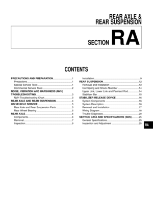
Page 9 of 26
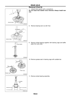
7. Unbend lock washer with a screwdriver.
Do not reuse lock washer once removed. Always install new
one.
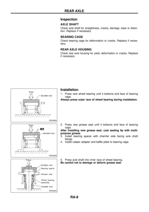
8. Remove bearing lock nut with Tool.
9. Remove wheel bearing together with bearing cage and baffle
plate from axle shaft.
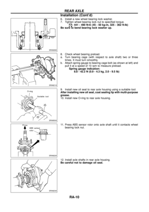
10. Remove grease seal in bearing cage with suitable bar.
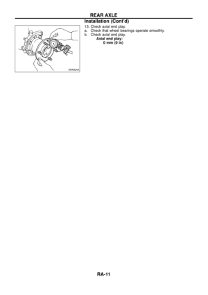
11. Remove wheel bearing assembly.
SRA847A
SRA817A
SRA800A
SRA595C
SRA801AA
REAR AXLE
Removal (Cont'd)
RA-8
Page 10 of 26
Inspection
AXLE SHAFT
Check axle shaft for straightness, cracks, damage, wear or distor-
tion. Replace if necessary.
BEARING CAGE
Check bearing cage for deformation or cracks. Replace if neces-
sary.
REAR AXLE HOUSING
Check rear axle housing for yield, deformation or cracks. Replace
if necessary.
Installation
1. Press new wheel bearing until it bottoms end face of bearing
cage.
Always press outer race of wheel bearing during installation.
2. Press new grease seal until it bottoms end face of bearing
cage.
After installing new grease seal, coat sealing lip with multi-
purpose grease.
3. Install bearing spacer with chamfer side facing axle shaft
¯ange.
4. Install caliper adapter and baffle plate to bearing cage.
5. Press axle shaft into inner race of wheel bearing.
Be careful not to damage or deform grease seal.
SRA288A
SRA289A
SRA849A
REAR AXLE
RA-9
Page 11 of 26
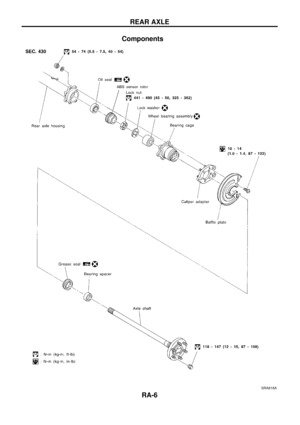
6. Install a new wheel bearing lock washer.
7. Tighten wheel bearing lock nut to speci®ed torque.
: 441 - 490 Nzm (45 - 50 kg-m, 325 - 362 ft-lb)
Be sure to bend bearing lock washer up.
8. Check wheel bearing preload.
a. Turn bearing cage (with respect to axle shaft) two or three
times. It must turn smoothly.
b. Attach spring gauge to bearing cage bolt (as shown at left) and
pull it at a speed of 10 rpm to measure preload.
Spring gauge indication:
8.8 - 42.2 N (0.9 - 4.3 kg, 2.0 - 9.5 lb)
9. Install new oil seal to rear axle housing using a suitable tool.
After installing new oil seal, coat sealing lip with multi-purpose
grease.
10. Install new O-ring to rear axle housing.
11. Press ABS sensor rotor onto axle shaft until it contacts wheel
bearing lock nut.
12. Install axle shafts in rear axle housing.
Be careful not to damage oil seal.
SRA828A
SRA821A
SRA850A
SRA822A
SRA823A
REAR AXLE
Installation (Cont'd)
RA-10
Page 12 of 26
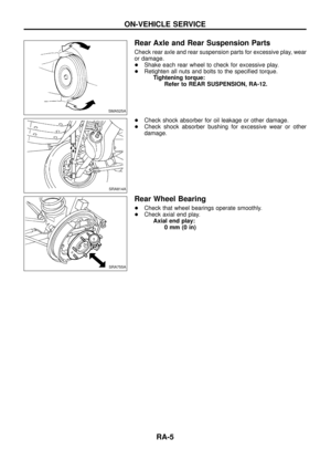
13. Check axial end play.
a. Check that wheel bearings operate smoothly.
b. Check axial end play.
Axial end play:
0mm(0in)
SRA824A
REAR AXLE
Installation (Cont'd)
RA-11
Page 13 of 26
SRA819A
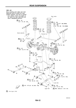
REAR SUSPENSION
RA-12
Page 14 of 26
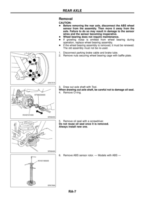
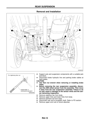
Removal and Installation
+Support axle and suspension components with a suitable jack
and block.
+Disconnect brake hydraulic line and parking brake cables at
back plates.
CAUTION:
+Use ¯are nut wrench when removing or installing brake
tubes.
+Before removing the rear suspension assembly, discon-
nect the ABS wheel sensor from the assembly. Then move
it away from the rear suspension assembly. Failure to do
so may result in damage to the sensor wires and the sen-
sor becoming inoperative.
+Remove stabilizer bar from body.
+Remove upper links and lower links from body.
+Remove panhard rod from body.
+Disconnect rear end of propeller shaft. Refer to PD section.
+Remove upper end nuts of shock absorber.
SRA825A
SBR820BA
REAR SUSPENSION
RA-13
Page 15 of 26

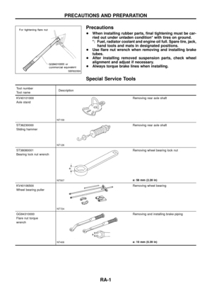
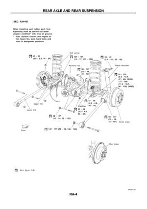
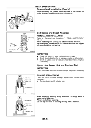
Final tightening for rubber parts requires to be carried out
under unladen condition with tires on ground.
Coil Spring and Shock Absorber
REMOVAL AND INSTALLATION
Refer to ``Removal and Installation'', ``REAR SUSPENSION'',
RA-13.
When installing coil spring, pay attention to its direction.
Be sure spring rubber seat is not twisted and has not slipped
off when installing coil spring.
INSPECTION
+Check coil spring for yield, deformation or cracks.
+Check shock absorber for oil leakage, cracks or deformation.
+Check all rubber parts for wear, cracks or deformation. Replace
if necessary.
Upper Link, Lower Link and Panhard Rod
INSPECTION
Check for cracks, distortion or other damage. Replace if necessary.
BUSHING REPLACEMENT
Check for cracks or other damage. Replace with suitable tool if
necessary.
+Remove bushing with suitable tool.
When installing bushing, apply a coat of 1% soapy water to
outer wall of bushing.
Always install new bushing.
Do not tap end face of bushing directly with a hammer.
SRA851A
SRA852A
SRA898
SRA900
REAR SUSPENSION
Removal and Installation (Cont'd)
RA-14
Page 16 of 26
INSTALLATION
When installing each link, pay attention to direction of nuts
and bolts.
When installing each rubber part, ®nal tightening must be car-
ried out under unladen condition with tires on ground.
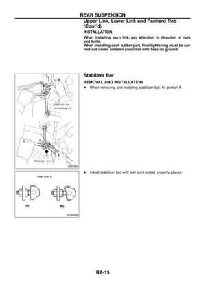
Stabilizer Bar
REMOVAL AND INSTALLATION
+When removing and installing stabilizer bar, ®x portion A.
+Install stabilizer bar with ball joint socket properly placed.
SRA766A
SFA449BA
REAR SUSPENSION
Upper Link, Lower Link and Panhard Rod
(Cont'd)
RA-15


Be sure to bend bearing lock washer up.
8. Check whee")

SRA824A
REAR AXLE
Installation (Contd)
RA-11")


