Page 17 of 26
 on good roads. On rough
roads, deactivating the stabilizer function (turning the stabiliz")
System Components
Roll rigidity is increased by activating the stabilizer function (turning the stabilizer ON) on good roads. On rough
roads, deactivating the stabilizer function (turning the stabilizer OFF) reduces stabilizer swing-back behavior.
As a result, the stabilizer release device serves to increase driving capability and riding comfort on rough roads.
The stabilizer release device is electrically activated (turned ON) or deactivated (turned OFF) by the stabilizer
switch in the driver's compartment.
System Description
CONTROL UNIT
The stabilizer control unit controls the actuator motor using the
stabilizer switch and a signal sent from the vehicle speed sensor.
When vehicle speed exceeds 20 km/h (12 MPH), the stabilizer
control unit maintains the clutch cylinder position and activates the
stabilizer function, regardless of the position of the stabilizer switch.
The system is provided with a timer function to cut the actuator
activating power output in about 15 seconds, in consideration of a
possible system abnormality.
ACTUATOR
The actuator motor is turned on by a signal sent from the control
unit. When the motor operates, the cable moves to activate the
stopper pin at the end of the cable.
CLUTCH CYLINDER
The stopper pin (at the end of the cable) moves in and out of the
cylinder (toward the piston rod or away from the piston rod) to turn
the stabilizer ON or OFF.
SRA832A
SRA833A
SRA834A
STABILIZER RELEASE DEVICE
RA-16
Page 18 of 26
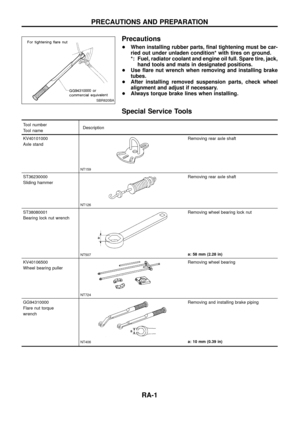
Removal and Installation
1. Loosen the lock nut C, and loosen the A nut. Remove the cable
from the clutch cylinder.
CAUTION:
+Do not remove the B nut because this requires the inner
cable extension adjustment.
+Before installing the A and C nuts, use seal tape to wrap
the clutch cylinder thread area and cable thread area.
2. Remove the clamp and other fasteners which secure the cable.
3. Remove the stabilizer actuator connector.
4. Remove the stabilizer actuator.
5. Remove the clutch cylinder.
6. Before removing the stabilizer control unit, remove cluster lid C
and audio equipment. Refer to the BT section ``INSTRUMENT
PANEL''.
SRA835A
SRA836A
SRA837A
STABILIZER RELEASE DEVICE
RA-17
Page 19 of 26
Wiring Diagram
TRA001
STABILIZER RELEASE DEVICE
RA-18
Page 20 of 26
TRA002
STABILIZER RELEASE DEVICE
Wiring Diagram (Cont'd)
RA-19
Page 21 of 26
Trouble Diagnoses
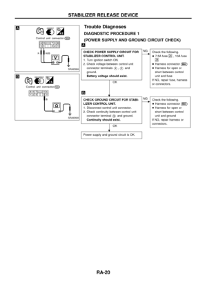
DIAGNOSTIC PROCEDURE 1
(POWER SUPPLY AND GROUND CIRCUIT CHECK)
CHECK POWER SUPPLY CIRCUIT FOR
STABILIZER CONTROL UNIT.
1. Turn ignition switch ON.
2. Check voltage between control unit
connector terminals
V4,V5and
ground.
Battery voltage should exist.
OK
cNG
Check the following.
+7.5A fuse
24, 10A fuse
28
+Harness connectorM44
+Harness for open or
short between control
unit and fuse
If NG, repair fuse, harness
or connectors.
CHECK GROUND CIRCUIT FOR STABI-
LIZER CONTROL UNIT.
1. Disconnect control unit connector.
2. Check continuity between control unit
connector terminal
V10and ground.
Continuity should exist.
OK
cNG
Check the following.
+Harness connector
M44
+Harness for open or
short between control
unit and ground
If NG, repair harness or
connectors.
Power supply and ground circuit is OK.
SRA838A
SRA839A
.
.
STABILIZER RELEASE DEVICE
RA-20
Page 22 of 26
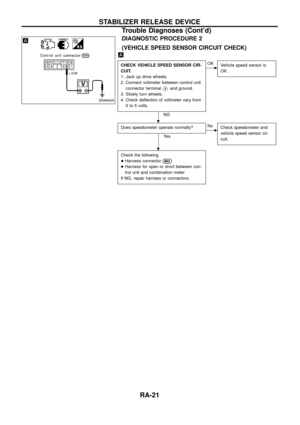
DIAGNOSTIC PROCEDURE 2
(VEHICLE SPEED SENSOR CIRCUIT CHECK)
CHECK VEHICLE SPEED SENSOR CIR-
CUIT.
1. Jack up drive wheels.
2. Connect voltmeter between control unit
connector terminal
V9and ground.
3. Slowly turn wheels.
4. Check de¯ection of voltmeter vary from
0 to 5 volts.
NG
cOK
Vehicle speed sensor is
OK.
Does speedometer operate normally?
Ye s
cNo
Check speedometer and
vehicle speed sensor cir-
cuit.
Check the following.
+Harness connector
M44
+Harness for open or short between con-
trol unit and combination meter
If NG, repair harness or connectors.
SRA840A
.
.
STABILIZER RELEASE DEVICE
Trouble Diagnoses (Cont'd)
RA-21
Page 23 of 26

1. Turn ignition switch ON.
2. Turn stabilizer switch ``OFF to make
sure stabilizer OFF illuminate.
OK
cNG
Check the following.
+10A fuse
28")
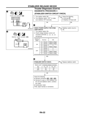
DIAGNOSTIC PROCEDURE 3
(STABILIZER SWITCH CIRCUIT CHECK)
1. Turn ignition switch ON.
2. Turn stabilizer switch ``OFF'' to make
sure stabilizer OFF illuminate.
OK
cNG
Check the following.
+10A fuse
28
+Stabilizer off lamp bulb
OK
.
CHECK POWER SUPPLY FOR STABI-
LIZER SWITCH.
1. Turn ignition switch ON.
2. Check voltage between control unit
connector terminals
V1,V2,V3,V4
and ground.
NG
cOK
Stabilizer switch circuit is
OK.
STABILIZER SWITCH CHECK.
OK
cNG
Replace stabilizer switch.
Check the following.
+Harness connectors
M32,M44,M100
+Harness for open or short between con-
trol unit and stabilizer switch, combina-
tion meter
+Combination meter
If NG, repair harness or connectors.
Stabilizer
switchTerminal Volt
ON
V1- Ground Battery voltage
V2- Ground Battery voltage
V3- Ground 0
V4- Ground Battery voltage
OFF
V1- Ground 0
V2- Ground 0
V3- Ground Battery voltage
V4- Ground Battery voltage
Switch condi-
tionContinuity between terminals
V1-V3V2-V3
ON No Yes
OFF Yes No
SRA841A
SRA842A
.
.
.
STABILIZER RELEASE DEVICE
Trouble Diagnoses (Cont'd)
RA-22
Page 24 of 26

CHECK STABILIZER ACTUATOR CIR-
CUIT.
1. Turn ignition switch ON.
2. Check voltage between control unit
connector terminals
V6,V7,V8and
ground")
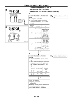
DIAGNOSTIC PROCEDURE 4
(STABILIZER ACTUATOR CIRCUIT CHECK)
CHECK STABILIZER ACTUATOR CIR-
CUIT.
1. Turn ignition switch ON.
2. Check voltage between control unit
connector terminals
V6,V7,V8and
ground.
NG
cOK
Stabilizer actuator circuit is
OK.
CHECK STABILIZER ACTUATOR
CHECK.
1. Disconnect stabilizer actuator connec-
tor.
2. Check stabilizer actuator by listening for
its operating sound while applying bat-
tery voltage to the terminals
V1and
V2.
OK
cNG
Replace stabilizer actuator.
Check the following.
+Harness connectors
M44,C4
+Harness for open or short between con-
trol unit and stabilizer actuator
If NG, repair harness or connectors.
Stabilizer
switchTerminal Volt
ON
V6- Ground 0
V7- GroundAfter turning sta-
bilizer switch
``ON'', battery
voltage will exist
for about 15
seconds, then
drop to 0 volts.
V8- Ground Approximately 4
OFF
V6- GroundAfter turning sta-
bilizer switch
``OFF'', battery
voltage will exist
for about 15
seconds, then
drop to 0 volts.
V7- Ground 0
V8- Ground Approximately 4
Terminal Clutch cylinderOperating
sound
V1-V2@ÅOFF®ON Yes
V1-V2Å@ON®OFF Yes
SRA843A
SRA844A
.
.
STABILIZER RELEASE DEVICE
Trouble Diagnoses (Cont'd)
RA-23


RA-19")

CHECK POWER SUPPLY CIRCUIT FOR
STABILIZER CONTROL UNIT.
1. Turn ignition switch ON.
2. Check voltage between control un")

CHECK VEHICLE SPEED SENSOR CIR-
CUIT.
1. Jack up drive wheels.
2. Connect voltmeter between control unit
connector terminal
V9and ground.
3.")