Page 2 of 26
Precautions
+When installing rubber parts, ®nal tightening must be car-
ried out under unladen condition* with tires on ground.
*: Fuel, radiator coolant and engine oil full. Spare tire, jack,
hand tools and mats in designated positions.
+Use ¯are nut wrench when removing and installing brake
tubes.
+After installing removed suspension parts, check wheel
alignment and adjust if necessary.
+Always torque brake lines when installing.
Special Service Tools
Tool number
Tool nameDescription
KV40101000
Axle stand
NT159
Removing rear axle shaft
ST36230000
Sliding hammer
NT126
Removing rear axle shaft
ST38080001
Bearing lock nut wrench
NT507
Removing wheel bearing lock nut
a: 58 mm (2.28 in)
KV40106500
Wheel bearing puller
NT724
Removing wheel bearing
GG94310000
Flare nut torque
wrench
NT406
Removing and installing brake piping
a: 10 mm (0.39 in)
SBR820BA
PRECAUTIONS AND PREPARATION
RA-1
Page 4 of 26

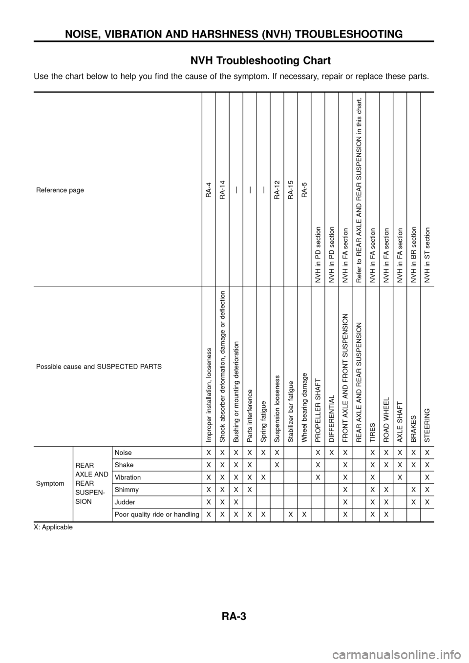
NVH Troubleshooting Chart
Use the chart below to help you ®nd the cause of the symptom. If necessary, repair or replace these parts.
Reference pageRA-4
RA-14
Ð
Ð
Ð
RA-12
RA-15
RA-5
NVH in PD section
NVH in PD section
NVH in FA section
Refer to REAR AXLE AND REAR SUSPENSION in this chart.
NVH in FA section
NVH in FA section
NVH in FA section
NVH in BR section
NVH in ST section
Possible cause and SUSPECTED PARTS
Improper installation, looseness
Shock absorber deformation, damage or de¯ection
Bushing or mounting deterioration
Parts interference
Spring fatigue
Suspension looseness
Stabilizer bar fatigue
Wheel bearing damage
PROPELLER SHAFT
DIFFERENTIAL
FRONT AXLE AND FRONT SUSPENSION
REAR AXLE AND REAR SUSPENSION
TIRES
ROAD WHEEL
AXLE SHAFT
BRAKES
STEERING
SymptomREAR
AXLE AND
REAR
SUSPEN-
SIONNoiseXXXXXX XXX XXXXX
ShakeXXXX X X X XXXXX
VibrationXXXXXXXXXX
ShimmyXXXX X XX XX
Judder X X X X X X X X
Poor quality ride or handlingXXXXX XX X XX
X: Applicable
NOISE, VIBRATION AND HARSHNESS (NVH) TROUBLESHOOTING
RA-3
Page 15 of 26

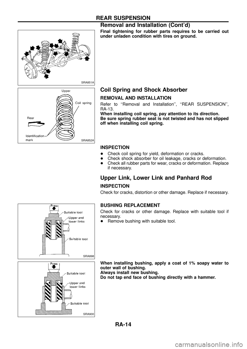
Final tightening for rubber parts requires to be carried out
under unladen condition with tires on ground.
Coil Spring and Shock Absorber
REMOVAL AND INSTALLATION
Refer to ``Removal and Installation'', ``REAR SUSPENSION'',
RA-13.
When installing coil spring, pay attention to its direction.
Be sure spring rubber seat is not twisted and has not slipped
off when installing coil spring.
INSPECTION
+Check coil spring for yield, deformation or cracks.
+Check shock absorber for oil leakage, cracks or deformation.
+Check all rubber parts for wear, cracks or deformation. Replace
if necessary.
Upper Link, Lower Link and Panhard Rod
INSPECTION
Check for cracks, distortion or other damage. Replace if necessary.
BUSHING REPLACEMENT
Check for cracks or other damage. Replace with suitable tool if
necessary.
+Remove bushing with suitable tool.
When installing bushing, apply a coat of 1% soapy water to
outer wall of bushing.
Always install new bushing.
Do not tap end face of bushing directly with a hammer.
SRA851A
SRA852A
SRA898
SRA900
REAR SUSPENSION
Removal and Installation (Cont'd)
RA-14
Page 16 of 26
INSTALLATION
When installing each link, pay attention to direction of nuts
and bolts.
When installing each rubber part, ®nal tightening must be car-
ried out under unladen condition with tires on ground.
Stabilizer Bar
REMOVAL AND INSTALLATION
+When removing and installing stabilizer bar, ®x portion A.
+Install stabilizer bar with ball joint socket properly placed.
SRA766A
SFA449BA
REAR SUSPENSION
Upper Link, Lower Link and Panhard Rod
(Cont'd)
RA-15