Page 25 of 54

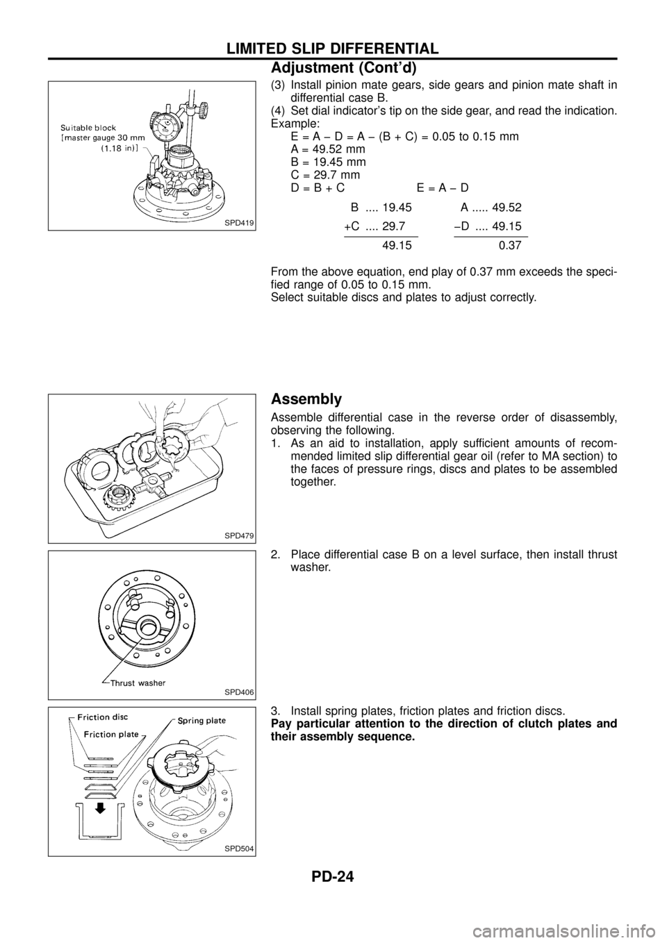
(3) Install pinion mate gears, side gears and pinion mate shaft in
differential case B.
(4) Set dial indicator's tip on the side gear, and read the indication.
Example:
E = A þ D = A þ (B + C) = 0.05 to 0.15 mm
A = 49.52 mm
B = 19.45 mm
C = 29.7 mm
D=B+C E=AþD
B .... 19.45 A ..... 49.52
+C .... 29.7 þD .... 49.15
49.150.37
From the above equation, end play of 0.37 mm exceeds the speci-
®ed range of 0.05 to 0.15 mm.
Select suitable discs and plates to adjust correctly.
Assembly
Assemble differential case in the reverse order of disassembly,
observing the following.
1. As an aid to installation, apply sufficient amounts of recom-
mended limited slip differential gear oil (refer to MA section) to
the faces of pressure rings, discs and plates to be assembled
together.
2. Place differential case B on a level surface, then install thrust
washer.
3. Install spring plates, friction plates and friction discs.
Pay particular attention to the direction of clutch plates and
their assembly sequence.
SPD419
SPD479
SPD406
SPD504
LIMITED SLIP DIFFERENTIAL
Adjustment (Cont'd)
PD-24
Page 26 of 54
4. Install pressure ring.
5. Install side gear by inserting projected portion of disc.
6. Install pinion mate gears and shaft.
Always attach pinion mate shaft to ``V'' groove in pressure ring
with ¯at surfaces facing up and down.
7. Install thrust block.
8. Install differential case A side components in the opposite way
of differential case B components.
9. Apply gear oil to differential case A, and attach thrust washer
to it.
SPD481
SPD482
SPD483
SPD505
SPD506
LIMITED SLIP DIFFERENTIAL
Assembly (Cont'd)
PD-25
Page 30 of 54
![NISSAN PATROL 1998 Y61 / 5.G Propeller Shaft And Differential Carrier Workshop Manual Example (H233B):
N = 0.30
H=2
D¢=þ1
S=0
T=Nþ[(HþD¢þ S) x 0.01] + 3.05
= 0.30 þ [{2 þ (þ1) þ 0} x 0.01] + 3.05
(1) H ........................................................................ 2 NISSAN PATROL 1998 Y61 / 5.G Propeller Shaft And Differential Carrier Workshop Manual Example (H233B):
N = 0.30
H=2
D¢=þ1
S=0
T=Nþ[(HþD¢þ S) x 0.01] + 3.05
= 0.30 þ [{2 þ (þ1) þ 0} x 0.01] + 3.05
(1) H ........................................................................ 2](/manual-img/5/625/w960_625-29.png)
Example (H233B):
N = 0.30
H=2
D¢=þ1
S=0
T=Nþ[(HþD¢þ S) x 0.01] + 3.05
= 0.30 þ [{2 þ (þ1) þ 0} x 0.01] + 3.05
(1) H ........................................................................ 2
þD¢................................................................. þ(þ1)
3
þS ...................................................................... þ0
3
(2) 3
x 0.01
0.03
(3) N ................................................................... 0.30
þ0.03
0.27
(4) 0.27
+3.05
3.32
\T = 3.32
7. Select the proper pinion height washer.
Drive pinion height adjusting washer:
Refer to SDS (PD-0, 53).
If you cannot ®nd the desired thickness of washer, use washer
with thickness closest to the calculated value.
Example (H233B):
Calculated value ... T = 3.32 mm
Used washer ... T = 3.33 mm
Tooth Contact
Gear tooth contact pattern check is necessary to verify correct
relationship between ring gear and drive pinion.
Hypoid gear sets which are not positioned properly in relation to
one another may be noisy, or have short life or both. With a pat-
tern check, the most desirable contact for low noise level and long
life can be assured.
1. Thoroughly clean ring gear and drive pinion teeth.
2. Sparingly apply a mixture of powdered ferric oxide and oil or
equivalent to 3 or 4 teeth of ring gear drive side.
SPD005
ADJUSTMENT
Drive Pinion Height (Cont'd)
PD-29
Page 32 of 54
Differential Case Ð 4-pinion type Ð
1. Measure clearance between side gear thrust washer and dif-
ferential case.
Clearance between side gear thrust washer
and differential case (A Ð B):
0.15 - 0.20 mm (0.0059 - 0.0079 in)
The clearance can be adjusted with side gear thrust washer.
Refer to SDS.
2. Apply oil to gear tooth surfaces and thrust surfaces and check
that they turn properly.
3. Install differential case LH and RH.
4. Place differential case on ring gear.
5. Apply locking sealer to ring gear bolts, and install them.
Tighten bolts in a criss-cross fashion, lightly tapping bolt head
with a hammer.
6. Press-®t side bearing inner races on differential case with Tool.
Tool number:
j
AST33190000
j
BST02371000
SPD656
SPD643
SPD746
PD353
ASSEMBLY
PD-31
Page 33 of 54
Differential Case Ð 2-pinion type Ð
1. Install side gears, pinion mate gears and thrust washers into
differential case.
2. Fit pinion mate shaft to differential case so that it meets lock pin
holes.
3. Adjust backlash between side gear and pinion mate gear by
selecting side gear thrust washer. Refer to SDS.
Backlash between side gear and pinion mate gear
(Clearance between side gear thrust washer and dif-
ferential case):
0.15 - 0.20 mm (0.0059 - 0.0079 in)
4. Install pinion mate shaft lock pin with a punch.
Make sure lock pin is ¯ush with case.
5. Apply gear oil to gear tooth surfaces and thrust surfaces and
make sure they turn properly.
6. Install differential case assembly on ring gear.
Tighten bolts in a criss-cross pattern, lightly tapping bolt head
with a hammer.
7. Press-®t side bearing inner cones on differential case with Tool.
Tool number:
j
AST33190000
j
BST02371000
SPD552
SPD258
SPD030
SPD322
PD353
ASSEMBLY
PD-32
Page 34 of 54
Differential Carrier
1. Press-®t front and rear bearing outer races with Tools.
Tool number:
j
AST30611000
j
BST30621000 (front differential)
or suitable pipe
j
CST30701000
CAUTION:
Do not damage roller side face.
2. Select drive pinion height adjusting washer. Refer to ADJUST-
MENT (PD-27).
3. Install drive pinion height adjusting washer in drive pinion, and
press-®t pinion rear bearing inner cone in it, with press and
Tool.
Tool number: ST30911000
4. Place pinion front bearing inner cone in gear carrier.
5. Apply multi-purpose grease to cavity at sealing lips of oil seal.
Install front oil seal.
Tool number:
j
AST30720000
j
BKV38102510
SPD580
SPD377
SPD581
SPD451A
ASSEMBLY
PD-33
Page 35 of 54

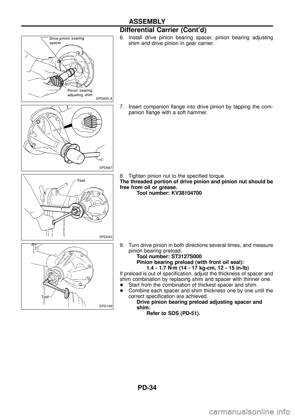
6. Install drive pinion bearing spacer, pinion bearing adjusting
shim and drive pinion in gear carrier.
7. Insert companion ¯ange into drive pinion by tapping the com-
panion ¯ange with a soft hammer.
8. Tighten pinion nut to the speci®ed torque.
The threaded portion of drive pinion and pinion nut should be
free from oil or grease.
Tool number: KV38104700
9. Turn drive pinion in both directions several times, and measure
pinion bearing preload.
Tool number: ST3127S000
Pinion bearing preload (with front oil seal):
1.4 - 1.7 Nzm (14 - 17 kg-cm, 12 - 15 in-lb)
If preload is out of speci®cation, adjust the thickness of spacer and
shim combination by replacing shim and spacer with thinner one.
+Start from the combination of thickest spacer and shim.
+Combine each spacer and shim thickness one by one until the
correct speci®cation are achieved.
Drive pinion bearing preload adjusting spacer and
shim:
Refer to SDS (PD-51).
SPD935-A
SPD697
SPD040
SPD149
ASSEMBLY
Differential Carrier (Cont'd)
PD-34
Page 36 of 54

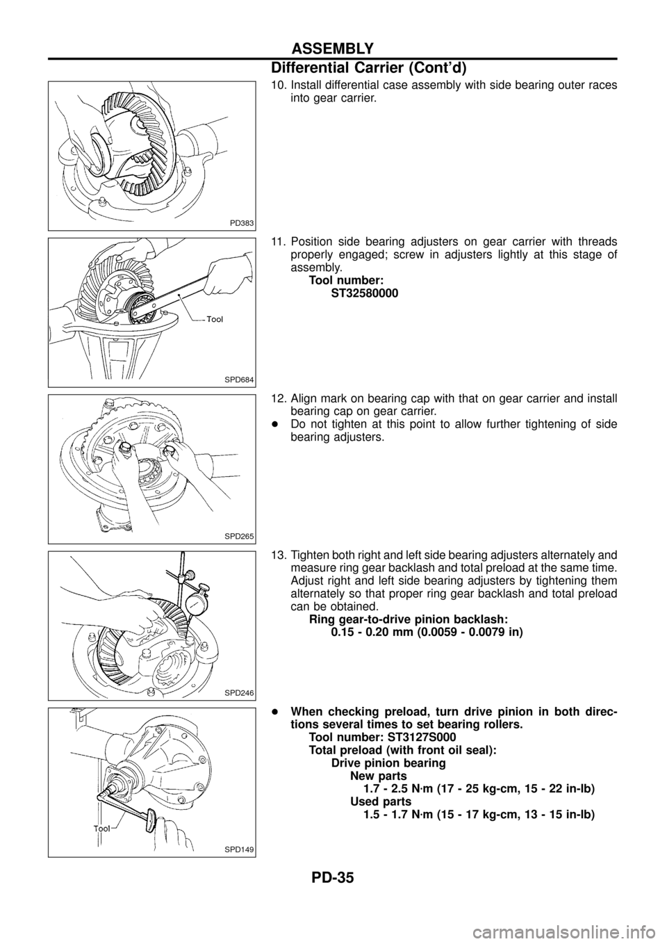
10. Install differential case assembly with side bearing outer races
into gear carrier.
11. Position side bearing adjusters on gear carrier with threads
properly engaged; screw in adjusters lightly at this stage of
assembly.
Tool number:
ST32580000
12. Align mark on bearing cap with that on gear carrier and install
bearing cap on gear carrier.
+Do not tighten at this point to allow further tightening of side
bearing adjusters.
13. Tighten both right and left side bearing adjusters alternately and
measure ring gear backlash and total preload at the same time.
Adjust right and left side bearing adjusters by tightening them
alternately so that proper ring gear backlash and total preload
can be obtained.
Ring gear-to-drive pinion backlash:
0.15 - 0.20 mm (0.0059 - 0.0079 in)
+When checking preload, turn drive pinion in both direc-
tions several times to set bearing rollers.
Tool number: ST3127S000
Total preload (with front oil seal):
Drive pinion bearing
New parts
1.7 - 2.5 Nzm (17 - 25 kg-cm, 15 - 22 in-lb)
Used parts
1.5 - 1.7 Nzm (15 - 17 kg-cm, 13 - 15 in-lb)
PD383
SPD684
SPD265
SPD246
SPD149
ASSEMBLY
Differential Carrier (Cont'd)
PD-35