Page 67 of 128
jA
STEP 2 - SENSOR CIRCUITS ARE
CHECKED FOR OPEN OR SHORT
CIRCUIT.
Does code No.
appear on the dis-
play?
Ye sNo
.
Turn temperature
dial clockwise.Refer to the following chart for malfunctioning code
No.
(If two or more sensors malfunction, corresponding
code Nos. blink respectively two times.)
*1: Conduct self-diagnosis STEP 2 under sunshine.
When conducting indoors, aim a light (more than
60W) at sunload sensor, otherwise Code No.
will indicate despite that sunload sensor is func-
tioning properly. j
B
(Go to next page.)
Code No.Malfunctioning sensor
(including circuits)Reference
page
Ambient sensor HA-103A/C LED
In-vehicle sensor HA-105A/C LED
Sunload sensor*1 HA-107A/C LED
Air mix door motor
(LCU) PBRHA-79
A/C LED
RHA970DA
RHA528G
RHA501A
.
.
.
TROUBLE DIAGNOSESAUTO
Self-diagnosis (Cont'd)
HA-65
Page 68 of 128
jB
STEP 3 - MODE DOOR POSITIONS
ARE CHECKED.
Does code No.
appear on the dis-
play?
Ye sNo
.
Turn temperature
dial clockwise.Mode door motor position switch is malfunctioning.
(If two or more mode doors are out of order, corre-
sponding code numbers blink respectively two
times.)
*1: If mode door motor harness connector is
disconnected, the following display pattern will
appear.
®
®®®®þ
jC
(Go to next page.)
Code
No.*1Mode door positionReference
page
VENT
HA-75
B/L
FOOT
F/D
DEF
RHA869DC
RHA168DA
RHA498A
.
.
.
TROUBLE DIAGNOSESAUTO
Self-diagnosis (Cont'd)
HA-66
Page 70 of 128
AUXILIARY MECHANISM: Temperature setting trimmer
The trimmer compensates for differences in range of 3ÉC between
temperature setting (displayed digitally) and temperature felt by
driver.
Operating procedures for this trimmer are as follows:
+Begin Self-diagnosis STEP 4 mode.
+Press
(fan) switch to set system in auxiliary mode.
+Turn temperature dial clockwise or counterclockwise as
desired. Temperature will change at a rate of 1ÉC each time a
switch is pressed.
When battery cable is disconnected, trimmer operation is can-
celed. Temperature set becomes that of initial condition, i.e.
0ÉC.
RHA581G
TROUBLE DIAGNOSESAUTO
Self-diagnosis (Cont'd)
HA-68
Page 73 of 128
b. Con®rm that discharge air comes out according to the air dis-
tribution table at left.
Refer to ``Discharge Air Flow'' (HA-13).
NOTE:
Con®rm that the compressor clutch is engaged (visualinspec-
tion) and intake door position is at FRESH when the DEF
is selected.
Intake door position is checked in the next step.
4. Check recirculation
a. Press RECswitch.
Recirculation indicator should illuminate.
b. Listen for intake door position change (you should hear blower
sound change slightly).
5. Check temperature dial
a. Turn temperature dial counterclockwise until 18ÉC is displayed.
b. Check for cold air at discharge air outlets.
c. Turn temperature dial clockwise until 32ÉC is displayed.
d. Check for hot air at discharge air outlets.
RHA654FD
RHA521G
RHA522G
TROUBLE DIAGNOSESAUTO
Operational Check (Cont'd)
HA-71
Page 83 of 128

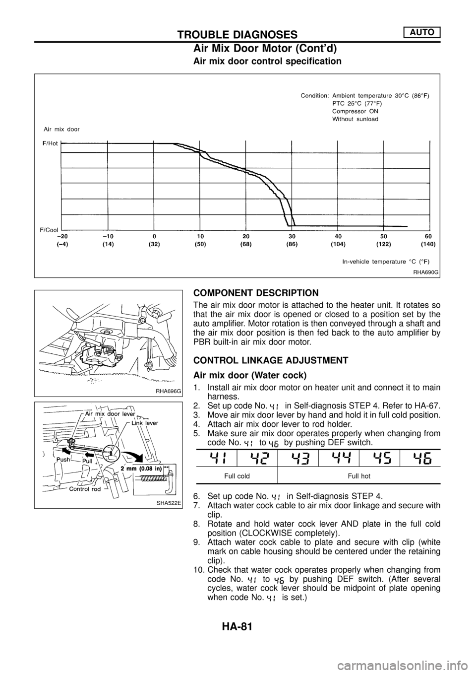
Air mix door control speci®cation
COMPONENT DESCRIPTION
The air mix door motor is attached to the heater unit. It rotates so
that the air mix door is opened or closed to a position set by the
auto ampli®er. Motor rotation is then conveyed through a shaft and
the air mix door position is then fed back to the auto ampli®er by
PBR built-in air mix door motor.
CONTROL LINKAGE ADJUSTMENT
Air mix door (Water cock)
1. Install air mix door motor on heater unit and connect it to main
harness.
2. Set up code No.
in Self-diagnosis STEP 4. Refer to HA-67.
3. Move air mix door lever by hand and hold it in full cold position.
4. Attach air mix door lever to rod holder.
5. Make sure air mix door operates properly when changing from
code No.
toby pushing DEF switch.
Full cold Full hot
6. Set up code No.in Self-diagnosis STEP 4.
7. Attach water cock cable to air mix door linkage and secure with
clip.
8. Rotate and hold water cock lever AND plate in the full cold
position (CLOCKWISE completely).
9. Attach water cock cable to plate and secure with clip (white
mark on cable housing should be centered under the retaining
clip).
10. Check that water cock operates properly when changing from
code No.
toby pushing DEF switch. (After several
cycles, water cock lever should be midpoint of plate opening
when code No.
is set.)
RHA690G
RHA696G
SHA522E
TROUBLE DIAGNOSESAUTO
Air Mix Door Motor (Cont'd)
HA-81
Page 87 of 128

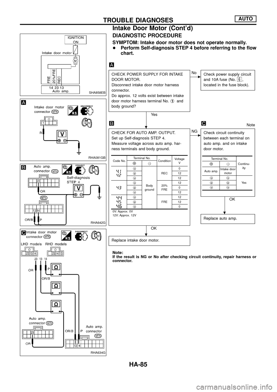
DIAGNOSTIC PROCEDURE
SYMPTOM: Intake door motor does not operate normally.
+Perform Self-diagnosis STEP 4 before referring to the ¯ow
chart.
CHECK POWER SUPPLY FOR INTAKE
DOOR MOTOR.
Disconnect intake door motor harness
connector.
Do approx. 12 volts exist between intake
door motor harness terminal No.j
1and
body ground?
Ye s
cNo
Check power supply circuit
and 10A fuse (No.
6,
located in the fuse block).
Note
CHECK FOR AUTO AMP. OUTPUT.
Set up Self-diagnosis STEP 4.
Measure voltage across auto amp. har-
ness terminals and body ground.
OK
cNG
Check circuit continuity
between each terminal on
auto amp. and on intake
door motor.
OK
Replace auto amp.
Replace intake door motor.
Note:If the result is NG or No after checking circuit continuity, repair harness or
connector.
Code No.Terminal No.
ConditionVoltage
VÅ@
j13
Body
groundREC0
j
2312
j
1412j1320%
FRE12
j230
j
1412j13
FRE12
j2312
j
140
0V: Approx. 0V
12V: Approx. 12V
Terminal No.
Continu-
ityÅ@
Auto amp.Intake door
motor
j
13j13
Ye s j23j23j14j14
SHA858EB
RHA081GB
RHA642G
RHA634G
.
.
.
TROUBLE DIAGNOSESAUTO
Intake Door Motor (Cont'd)
HA-85
Page 91 of 128

DIAGNOSTIC PROCEDURE
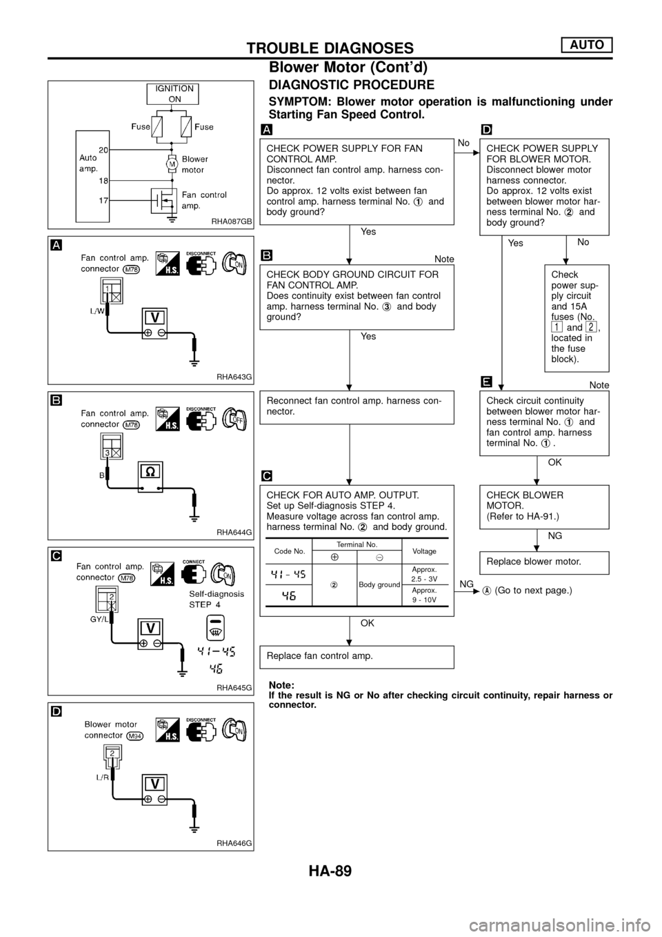
SYMPTOM: Blower motor operation is malfunctioning under
Starting Fan Speed Control.
CHECK POWER SUPPLY FOR FAN
CONTROL AMP.
Disconnect fan control amp. harness con-
nector.
Do approx. 12 volts exist between fan
control amp. harness terminal No.j
1and
body ground?
Ye s
cNo
CHECK POWER SUPPLY
FOR BLOWER MOTOR.
Disconnect blower motor
harness connector.
Do approx. 12 volts exist
between blower motor har-
ness terminal No.j
2and
body ground?
No
.
Ye s
Note
CHECK BODY GROUND CIRCUIT FOR
FAN CONTROL AMP.
Does continuity exist between fan control
amp. harness terminal No.j
3and body
ground?
Ye sCheck
power sup-
ply circuit
and 15A
fuses (No.1and2,
located in
the fuse
block).
Note
Reconnect fan control amp. harness con-
nector.
Check circuit continuity
between blower motor har-
ness terminal No.j
1and
fan control amp. harness
terminal No.j
1.
OK
CHECK FOR AUTO AMP. OUTPUT.
Set up Self-diagnosis STEP 4.
Measure voltage across fan control amp.
harness terminal No.j
2and body ground.
OKCHECK BLOWER
MOTOR.
(Refer to HA-91.)
NG
Replace blower motor.
cNG
jA(Go to next page.)
Replace fan control amp.
Note:If the result is NG or No after checking circuit continuity, repair harness or
connector.
Code No.Terminal No.
VoltageÅ@
þj2Body groundApprox.
2.5-3VApprox.
9 - 10V
RHA087GB
RHA643G
RHA644G
RHA645G
RHA646G
..
.
..
.
.
TROUBLE DIAGNOSESAUTO
Blower Motor (Cont'd)
HA-89
Page 92 of 128

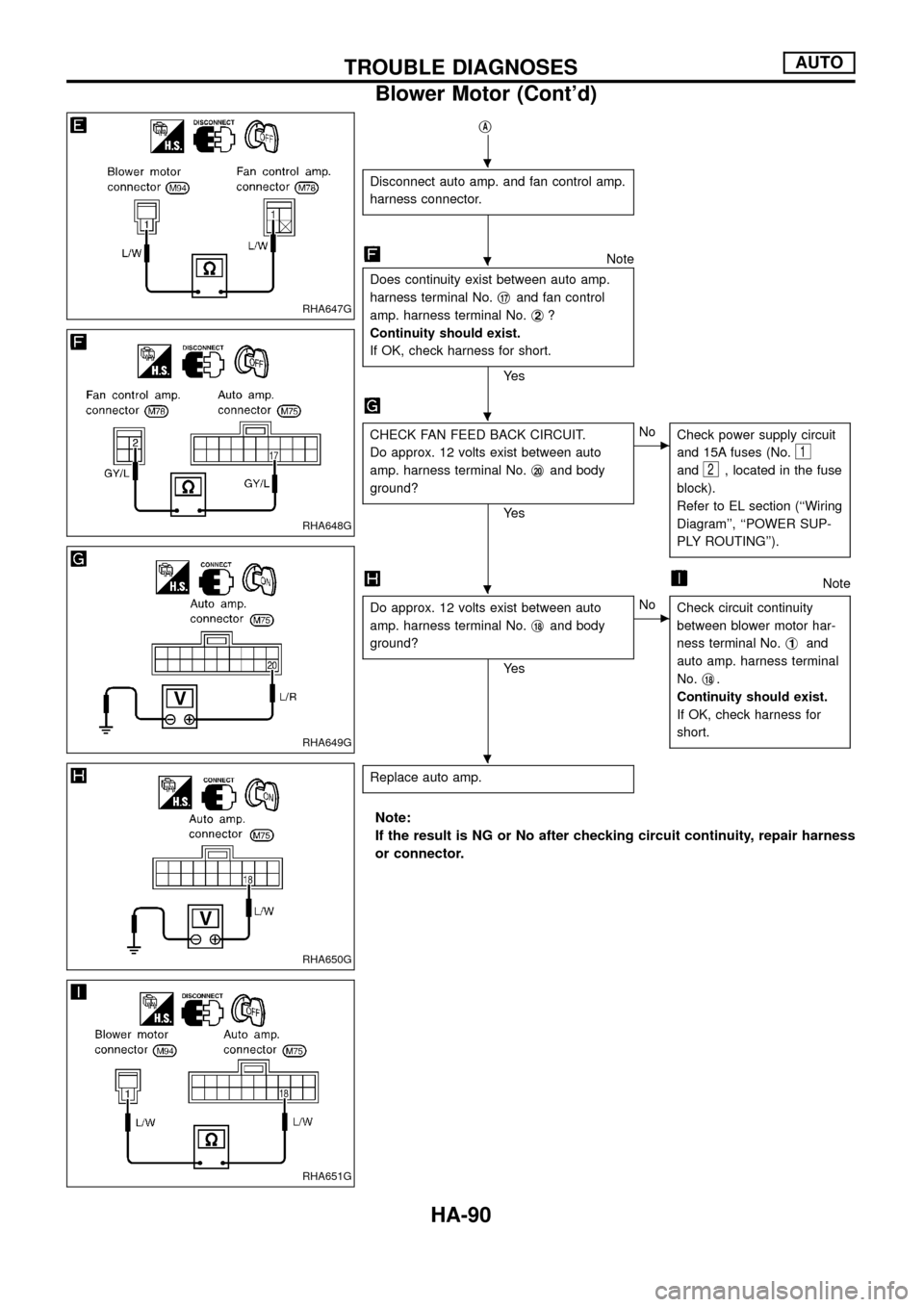
jA
Disconnect auto amp. and fan control amp.
harness connector.
Note
Does continuity exist between auto amp.
harness terminal No.j
17and fan control
amp. harness terminal No.j
2?
Continuity should exist.
If OK, check harness for short.
Ye s
CHECK FAN FEED BACK CIRCUIT.
Do approx. 12 volts exist between auto
amp. harness terminal No.j
20and body
ground?
Ye s
cNo
Check power supply circuit
and 15A fuses (No.
1
and2, located in the fuse
block).
Refer to EL section (``Wiring
Diagram'', ``POWER SUP-
PLY ROUTING'').
Note
Do approx. 12 volts exist between auto
amp. harness terminal No.j
18and body
ground?
Ye s
cNo
Check circuit continuity
between blower motor har-
ness terminal No.j
1and
auto amp. harness terminal
No.j
18.
Continuity should exist.
If OK, check harness for
short.
Replace auto amp.
Note:
If the result is NG or No after checking circuit continuity, repair harness
or connector.
RHA647G
RHA648G
RHA649G
RHA650G
RHA651G
.
.
.
.
.
TROUBLE DIAGNOSESAUTO
Blower Motor (Cont'd)
HA-90