Page 89 of 128

SYSTEM DESCRIPTION
Component parts
Fan speed control system components are:
1) Auto amp.
2) Fan control amp.
3) A/C LAN system (PBR built in mode door motor and air mix door motor)
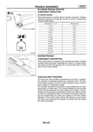
4) In-vehicle sensor
5) Ambient sensor
6) Sunload sensor
7) Intake sensor
System operation
Automatic mode
In the automatic mode, the blower motor speed is calculated by the automatic ampli®er based on inputs from
the PBR, in-vehicle sensor, sunload sensor, intake sensor and ambient sensor. The blower motor applied
voltage ranges from approximately 5 volts (lowest speed) to 12 volts (highest speed).
The control blower speed (in the range of 5 to 12V), the automatic ampli®er supplies a gate voltage to the fan
control ampli®er. Based on this voltage, the fan control ampli®er controls the voltage supplied to the blower
motor.
Starting fan speed control
Start up from ``COLD SOAK'' condition (Automatic mode)
In a cold start up condition where the engine coolant temperature is below 50ÉC, the blower will not operate
for a short period of time (up to 150 seconds). The exact start delay time varies depending on the ambient
and engine coolant temperature.
In the most extreme case (very low ambient) the blower starting delay will be 150 seconds as described above.
After this delay, the blower will operate at low speed until the engine coolant temperature rises above 55ÉC,
at which time the blower speed will increase to the objective speed.
Start up from normal or ``HOT SOAK'' condition (Automatic mode)
The blower will begin operation momentarily after the AUTO button is pushed. The blower speed will gradu-
ally rise to the objective speed over a time period of 3 seconds or less (actual time depends on the objective
blower speed).
SHA006FB
TROUBLE DIAGNOSESAUTO
Blower Motor (Cont'd)
HA-87
Page 90 of 128

Blower speed compensation
Sunload
When the in-vehicle temperature and the set temperature are very close, the blower will be operating at low
speed. The low speed will vary depending on the sunload. During conditions of high sunload, the blower low
speed is ``normal'' low speed (approx. 6V). During low or no sunload conditions, the low speed will drop to
``low'' low speed (approx. 5V).
Ambient
When the ambient temperature is in the ``moderate'' range [10 þ 15ÉC], the computed blower voltage will be
compensated (reduced) by up to 3.5V (depending on the blower speed). In the ``extreme'' ambient ranges
[below 0ÉC and above 20ÉC] the computed objective blower voltage is not compensated at all. In the ambi-
ent temperature ranges between ``moderate'' and ``extreme'' [0 - 10ÉC and 15 - 20ÉC], the amount of compen-
sation (for a given blower speed) varies depending on the ambient temperature.
Fan speed control speci®cation
COMPONENT DESCRIPTION
Fan control ampli®er
The fan control ampli®er is located on the cooling unit. The fan
control amp. receives a gate voltage from the auto amp. to step-
lessly maintain the blower fan motor voltage in the 5 to 12 volt
range (approx.).
RHA694G
RHA695G
TROUBLE DIAGNOSESAUTO
Blower Motor (Cont'd)
HA-88
Page 91 of 128

DIAGNOSTIC PROCEDURE
SYMPTOM: Blower motor operation is malfunctioning under
Starting Fan Speed Control.
CHECK POWER SUPPLY FOR FAN
CONTROL AMP.
Disconnect fan control amp. harness con-
nector.
Do approx. 12 volts exist between fan
control amp. harness terminal No.j
1and
body ground?
Ye s
cNo
CHECK POWER SUPPLY
FOR BLOWER MOTOR.
Disconnect blower motor
harness connector.
Do approx. 12 volts exist
between blower motor har-
ness terminal No.j
2and
body ground?
No
.
Ye s
Note
CHECK BODY GROUND CIRCUIT FOR
FAN CONTROL AMP.
Does continuity exist between fan control
amp. harness terminal No.j
3and body
ground?
Ye sCheck
power sup-
ply circuit
and 15A
fuses (No.1and2,
located in
the fuse
block).
Note
Reconnect fan control amp. harness con-
nector.
Check circuit continuity
between blower motor har-
ness terminal No.j
1and
fan control amp. harness
terminal No.j
1.
OK
CHECK FOR AUTO AMP. OUTPUT.
Set up Self-diagnosis STEP 4.
Measure voltage across fan control amp.
harness terminal No.j
2and body ground.
OKCHECK BLOWER
MOTOR.
(Refer to HA-91.)
NG
Replace blower motor.
cNG
jA(Go to next page.)
Replace fan control amp.
Note:If the result is NG or No after checking circuit continuity, repair harness or
connector.
Code No.Terminal No.
VoltageÅ@
þj2Body groundApprox.
2.5-3VApprox.
9 - 10V
RHA087GB
RHA643G
RHA644G
RHA645G
RHA646G
..
.
..
.
.
TROUBLE DIAGNOSESAUTO
Blower Motor (Cont'd)
HA-89
Page 92 of 128

jA
Disconnect auto amp. and fan control amp.
harness connector.
Note
Does continuity exist between auto amp.
harness terminal No.j
17and fan control
amp. harness terminal No.j
2?
Continuity should exist.
If OK, check harness for short.
Ye s
CHECK FAN FEED BACK CIRCUIT.
Do approx. 12 volts exist between auto
amp. harness terminal No.j
20and body
ground?
Ye s
cNo
Check power supply circuit
and 15A fuses (No.
1
and2, located in the fuse
block).
Refer to EL section (``Wiring
Diagram'', ``POWER SUP-
PLY ROUTING'').
Note
Do approx. 12 volts exist between auto
amp. harness terminal No.j
18and body
ground?
Ye s
cNo
Check circuit continuity
between blower motor har-
ness terminal No.j
1and
auto amp. harness terminal
No.j
18.
Continuity should exist.
If OK, check harness for
short.
Replace auto amp.
Note:
If the result is NG or No after checking circuit continuity, repair harness
or connector.
RHA647G
RHA648G
RHA649G
RHA650G
RHA651G
.
.
.
.
.
TROUBLE DIAGNOSESAUTO
Blower Motor (Cont'd)
HA-90
Page 93 of 128
COMPONENT INSPECTION
Blower motor
Con®rm smooth rotation of the blower motor.
+Ensure that there are no foreign particles inside the intake unit.
RHA941F
TROUBLE DIAGNOSESAUTO
Blower Motor (Cont'd)
HA-91
Page 94 of 128
Magnet Clutch
TROUBLE DIAGNOSIS PROCEDURE FOR MAGNET CLUTCH
SYMPTOM:
+Magnet clutch does not engage.
Inspection ¯ow
*1: HA-64
*2: HA-65
*3: HA-67
*4: HA-94*5: HA-103
*6: HA-105
*7: HA-107
*8: HA-110*9: HA-79
*10: HA-70
*11: HA-69
*12: HA-35
SHA023F
TROUBLE DIAGNOSESAUTO
HA-92
Page 95 of 128
SYSTEM DESCRIPTION
Auto ampli®er controls compressor operation by ambient tempera-
ture and signal from ECM (ECCS control module).
Low temperature protection control
Auto ampli®er will turn the compressor ``ON'' or ``OFF'' as deter-
mined by a signal detected by ambient sensor.
When ambient temperatures are greater than 1ÉC, the compressor
turns ``ON''. The compressor turns ``OFF'' when ambient tempera-
tures are less than þ2ÉC.
RHA094GA
TROUBLE DIAGNOSESAUTO
Magnet Clutch (Cont'd)
HA-93
Page 96 of 128

DIAGNOSTIC PROCEDURE
SYMPTOM: Magnet clutch does not engage when A/C switch
and fan switch are ON.
CHECK POWER SUPPLY FOR COM-
PRESSOR.
Disconnect compressor harness connector.
Do approx. 12 volts exist between compres-
sor harness terminal No.j
1and body
ground?
No
cYe s
Check magnet clutch coil.
NG
Replace magnet clutch.
Refer to HA-123.
Disconnect A/C relay.
Note
CHECK CIRCUIT CONTINUITY
BETWEEN A/C RELAY HARNESS TERMI-
NAL NO.j
7AND COMPRESSOR HAR-
NESS TERMINAL NO.j1.
Continuity should exist.
If OK, check harness for short.
OK
CHECK POWER SUPPLY FOR A/C
RELAY.
Disconnect A/C relay.
Do approx. 12 volts exist between A/C
relay harness terminal Nos.j
1,j6and
body ground?
Ye s
cNo
CHECK POWER SUPPLY
CIRCUIT AND 10A (No.
) FUSE AT FUSE
BLOCK.
Refer to EL section (``Wiring
Diagram'', ``POWER SUP-
PLY ROUTING'').
CHECK A/C RELAY AFTER DISCON-
NECTING IT.
Refer to HA-97.
OK OK
ECCS
engine
modelsExcept for
ECCS
engine
models
cNG
Replace A/C relay.
jA(Go to next page.)jB
Note:
If the result is NG or No after checking circuit continuity, repair harness or
connector.
RHA652G
RHA096GA
RHA653G
RHA654G
.
.
.
.
.
..
TROUBLE DIAGNOSESAUTO
Magnet Clutch (Cont'd)
HA-94