Page 25 of 47

Circuit Inspection
INTRODUCTION
In general, testing electrical circuits is an easy task if it is approached in a logical and organized method. Before
beginning it is important to have all available information on the system to be tested. Also, get a thorough
understanding of system operation. Then you will be able to use the appropriate equipment and follow the
correct test procedure.
You may have to simulate vehicle vibrations while testing electrical components.Gently shakethe wiring
harness or electrical component to do this.
OPEN A circuit is open when there is no continuity through a section of the circuit.
SHORT There are two types of shorts.
+SHORT CIRCUITWhen a circuit contacts another circuit and causes the
normal resistance to change.
+SHORT TO GROUNDWhen a circuit contacts a ground source and grounds the
circuit.
TESTING FOR ``OPENS'' IN THE CIRCUIT
Before you begin to diagnose and test the system, you should rough sketch a schematic of the system. This
will help you to logically walk through the diagnosis process. Drawing the sketch will also reinforce your work-
ing knowledge of the system.
Continuity check method
The continuity check is used to ®nd an open in the circuit. The Digital Multimeter (DMM) set on the resistance
function will indicate an open circuit as over limit (OL, no beep tone or no ohms symbol). Make sure to always
start with the DMM at the highest resistance level.
To help in understanding the diagnosis of open circuits please refer to the schematic above.
1. Disconnect the battery negative cable.
2. Start at one end of the circuit and work your way to the other end. (At the fuse block in this example)
3. Connect one probe of the DMM to the fuse block terminal on the load side.
4. Connect the other probe to the fuse block (power) side of SW1. Little or no resistance will indicate that
portion of the circuit has good continuity. If there were an open in the circuit, the DMM would indicate an
over limit or in®nite resistance condition. (point A)
5. Connect the probes between SW1 and the relay. Little or no resistance will indicate that portion of the cir-
cuit has good continuity. If there were an open in the circuit, the DMM would indicate an over limit or in®-
nite resistance condition. (point B)
6. Connect the probes between the relay and the solenoid. Little or no resistance will indicate that portion of
the circuit has good continuity. If there were an open in the circuit, the DMM would indicate an over limit
or in®nite resistance condition. (point C)
Any circuit can be diagnosed using the approach in the above example.
SGI846
HOW TO PERFORM EFFICIENT DIAGNOSIS FOR AN ELECTRICAL INCIDENT
GI-24
Page 26 of 47

Voltage check method
To help in understanding the diagnosis of open circuits please refer to the previous schematic.
In any powered circuit, an open can be found by methodically checking the system for the presence of volt-
age. This is done by switching the DMM to the voltage function.
1. Connect one probe of the DMM to a known good ground.
2. Begin probing at one end of the circuit and work your way to the other end.
3. With SW1 open, probe at SW1 to check for voltage.
voltage; open is further down the circuit than SW1.
no voltage; open is between fuse block and SW1 (point A).
4. Close SW1 and probe at relay.
voltage; open is further down the circuit than the relay.
no voltage; open is between SW1 and relay (point B).
5. Close the relay and probe at the solenoid.
voltage; open is further down the circuit than the solenoid.
no voltage; open is between relay and solenoid (point C).
Any powered circuit can be diagnosed using the approach in the above example.
TESTING FOR ``SHORTS'' IN THE CIRCUIT
To simplify the discussion of shorts in the system please refer to the schematic below.
Resistance check method
1. Disconnect the battery negative cable and remove the blown fuse.
2. Disconnect all loads (SW1 open, relay disconnected and solenoid disconnected) powered through the
fuse.
3. Connect one probe of the ohmmeter to the load side of the fuse terminal. Connect the other probe to a
known good ground.
4. With SW1 open, check for continuity.
continuity; short is between fuse terminal and SW1 (point A).
no continuity; short is further down the circuit than SW1.
5. Close SW1 and disconnect the relay. Put probes at the load side of fuse terminal and a known good
ground. Then, check for continuity.
continuity; short is between SW1 and the relay (point B).
no continuity; short is further down the circuit than the relay.
6. Close SW1 and jump the relay contacts with jumper wire. Put probes at the load side of fuse terminal and
a known good ground. Then, check for continuity.
continuity; short is between relay and solenoid (point C).
no continuity; check solenoid, retrace steps.
SGI847
HOW TO PERFORM EFFICIENT DIAGNOSIS FOR AN ELECTRICAL INCIDENT
Circuit Inspection (Cont'd)
GI-25
Page 27 of 47
 powered through the fuse.
2. Turn the ignition key to the ON or S")
Voltage check method
1. Remove the blown fuse and disconnect all loads (i.e. SW1 open, relay disconnected and solenoid discon-
nected) powered through the fuse.
2. Turn the ignition key to the ON or START position. Verify battery voltage at the B
+side of the fuse ter-
minal (one lead on the B
+terminal side of the fuse block and one lead on a known good ground).
3. With SW1 open and the DMM leads across both fuse terminals, check for voltage.
voltage; short is between fuse block and SW1 (point A).
no voltage; short is further down the circuit than SW1.
4. With SW1 closed, relay and solenoid disconnected and the DMM leads across both fuse terminals, check
for voltage.
voltage; short is between SW1 and the relay (point B).
no voltage; short is further down the circuit than the relay.
5. With SW1 closed, relay contacts jumped with fused jumper wire check for voltage.
voltage; short is down the circuit of the relay or between the relay and the disconnected solenoid
(point C).
no voltage; retrace steps and check power to fuse block.
GROUND INSPECTION
Ground connections are very important to the proper operation of electrical and electronic circuits. Ground
connections are often exposed to moisture, dirt and other corrosive elements. The corrosion (rust) can become
an unwanted resistance. This unwanted resistance can change the way a circuit works.
Electronically controlled circuits are very sensitive to proper grounding. A loose or corroded ground can dras-
tically affect an electronically controlled circuit. A poor or corroded ground can easily affect the circuit. Even
when the ground connection looks clean, there can be a thin ®lm of rust on the surface.
When inspecting a ground connection follow these rules:
1. Remove the ground bolt screw or clip.
2. Inspect all mating surfaces for tarnish, dirt, rust, etc.
3. Clean as required to assure good contact.
4. Reinstall bolt or screw securely.
5. Inspect for ``add-on'' accessories which may be interfering with the ground circuit.
6. If several wires are crimped into one ground eyelet terminal, check for proper crimps. Make sure all of the
wires are clean, securely fastened and providing a good ground path. If multiple wires are cased in one
eyelet make sure no ground wires have excess wire insulation.
SGI853
HOW TO PERFORM EFFICIENT DIAGNOSIS FOR AN ELECTRICAL INCIDENT
Circuit Inspection (Cont'd)
GI-26
Page 28 of 47

VOLTAGE DROP TESTS
Voltage drop tests are often used to ®nd components or circuits which have excessive resistance. A voltage
drop in a circuit is caused by a resistancewhen the circuit is in operation.
Check the wire in the illustration. When measuring resistance with ohmmeter, contact by a single strand of
wire will give reading of 0 ohms. This would indicate a good circuit. When the circuit operates, this single strand
of wire is not able to carry the current. The single strand will have a high resistance to the current. This will
be picked up as a slight voltage drop.
Unwanted resistance can be caused by many situations as follows:
Undersized wiring (single strand example)
Corrosion on switch contacts
Loose wire connections or splices.
If repairs are needed always use wire that is of the same or larger gauge.
Measuring voltage drop Ð Accumulated method
1. Connect the voltmeter across the connector or part of the circuit you want to check. The positive lead of
the voltmeter should be closer to power and the negative lead closer to ground.
2. Operate the circuit.
3. The voltmeter will indicate how many volts are being used to ``push'' current through that part of the cir-
cuit.
Note in the illustration that there is an excessive 4.1 volt drop between the battery and the bulb.
Measuring voltage drop Ð Step by step
The step by step method is most useful for isolating excessive drops in low voltage systems (such as those
in ``Computer Controlled Systems'').
Circuits in the ``Computer Controlled System'' operate on very low amperage.
The (Computer Controlled) system operations can be adversely affected by any variation in resistance in the
system. Such resistance variation may be caused by poor connection, improper installation, improper wire
gauge or corrosion.
The step by step voltage drop test can identify a component or wire with too much resistance.
SGI974
HOW TO PERFORM EFFICIENT DIAGNOSIS FOR AN ELECTRICAL INCIDENT
Circuit Inspection (Cont'd)
GI-27
Page 29 of 47
SGI854
HOW TO PERFORM EFFICIENT DIAGNOSIS FOR AN ELECTRICAL INCIDENT
Circuit Inspection (Cont'd)
GI-28
Page 30 of 47
CONTROL UNIT CIRCUIT TEST
System Description: When the switch is ON, the control unit lights up the lamp.
AGI059
HOW TO PERFORM EFFICIENT DIAGNOSIS FOR AN ELECTRICAL INCIDENT
Circuit Inspection (Cont'd)
GI-29
Page 31 of 47
 Use the ¯ow chart after locating probable causes o")
NOTICE:
The ¯ow chart indicates work procedures required to diagnose
problems effectively. Observe the following instructions before
diagnosing.
1) Use the ¯ow chart after locating probable causes of a prob-
lem following the ``Preliminary Check'', the ``Symptom
Chart'' or the ``Work Flow''.
2) After repairs, re-check that the problem has been com-
pletely eliminated.
3) Refer to Component Parts and Harness Connector Loca-
tion for the Systems described in each section for
identi®cation/location of components and harness con-
nectors.
4) Refer to the Circuit Diagram for Quick Pinpoint Check.
If you must check circuit continuity between harness con-
nectors in more detail, such as when a sub-harness is
used, refer to Wiring Diagram in each individual section
and Harness Layout in EL section for identi®cation of har-
ness connectors.
5) When checking circuit continuity, ignition switch should
be ``OFF''.
6) Before checking voltage at connectors, check battery volt-
age.
7) After accomplishing the Diagnostic Procedures and Elec-
trical Components Inspection, make sure that all harness
connectors are reconnected as they were.
Example
AGI056
HOW TO FOLLOW FLOW CHART IN TROUBLE DIAGNOSES
GI-30
Page 32 of 47
 Turn ig")
How to Follow This Flow Chart
Work and diagnostic procedure
Start to diagnose a problem using procedures indicated in
enclosed blocks, as shown in the following example.
CHECK POWER SUPPLY.
1) Turn ignition switch ``ON''.
2) Check voltage between terminal
V1and ground.
Battery voltage should exist.
bCheck item being performed.
Procedure, steps or
measurement results
Measurement results
Required results are indicated in bold type in the correspond-
ing block, as shown below:
These have the following meanings:
Battery voltage®11 - 14V or approximately 12V
Voltage: Approximately 0V®Less than 1V
Cross reference of work symbols in the text and
illustrations
Illustrations are provided as visual aids for work procedures.
For example, symbol
indicated in the left upper portion of
each illustration corresponds with the symbol in the ¯ow chart
for easy identi®cation. More precisely, the procedure under the
``CHECK POWER SUPPLY'' outlined previously is indicated by
illustration
.
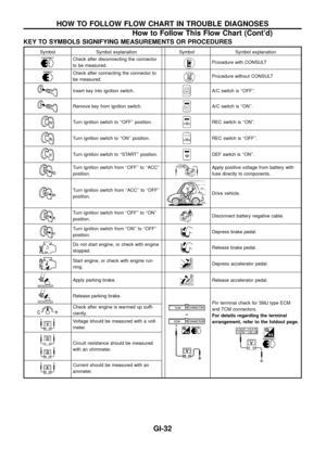
Symbols used in illustrations
Symbols included in illustrations refer to measurements or pro-
cedures. Before diagnosing a problem, familiarize yourself with
each symbol.
DIRECTION MARK
Refer to ``CONNECTOR SYMBOLS'' on GI-12.
HOW TO FOLLOW FLOW CHART IN TROUBLE DIAGNOSES
GI-31


GI-28")
