Page 38 of 75
Removal and Installation
CAUTION:
Be careful not to damage sensor edge and sensor rotor teeth.
When removing the front wheel hub or rear axle shaft
assembly, disconnect the ABS wheel sensor from the assem-
bly and move it away.
FRONT WHEEL SENSOR
SBR187E
ANTI-LOCK BRAKE SYSTEM
BR-36
Page 39 of 75
REAR WHEEL SENSOR
G SENSOR
Always replace G sensor if bumped or dropped. Otherwise,
performance characteristics of G sensor will be changed,
which in turn changes ABS control performance characteris-
tics.
SBR188E
SBR190E
ANTI-LOCK BRAKE SYSTEM
Removal and Installation (Cont'd)BR-37
Page 40 of 75
ABS ACTUATOR AND ELECTRIC UNIT
Removal
1. Disconnect battery cable.
2. Drain brake ¯uid. Refer to ``Changing Brake Fluid'', BR-3.
3. Remove mounting bracket ®xing bolts and nuts.
4. Disconnect connector, brake pipes and remove ®xing nuts.
Installation
CAUTION:
After installation, re®ll brake ¯uid. Then bleed air. Refer to
Bleeding Brake System'', BR-4.
1. Connect brake pipes temporarily.
2. Tighten ®xing bolts and nuts.
3. Tighten brake pipes.
4. Connect connector and battery cable.
SBR191E
ANTI-LOCK BRAKE SYSTEM
Removal and Installation (Cont'd)BR-38
Page 49 of 75

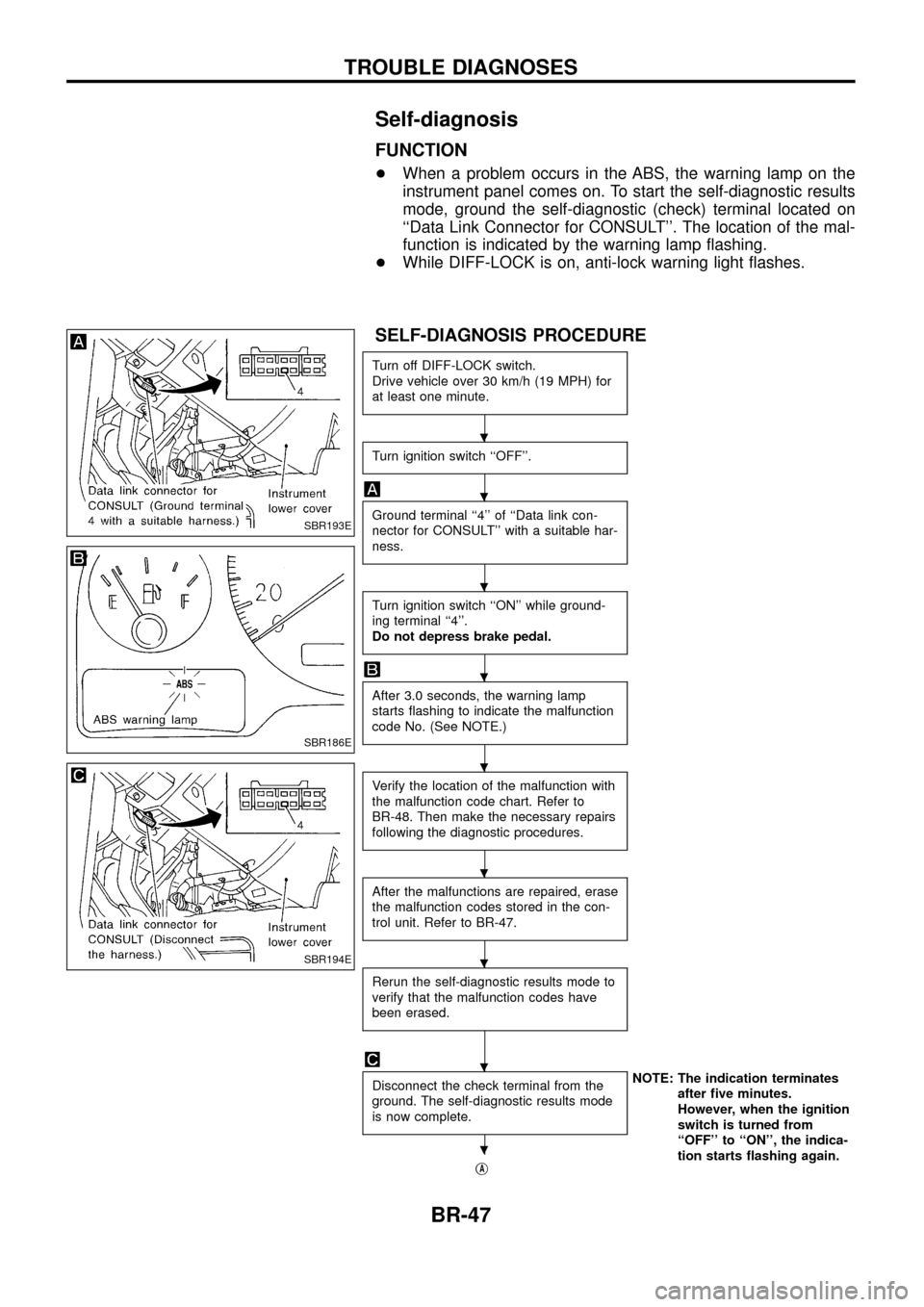
Self-diagnosis
FUNCTION
+When a problem occurs in the ABS, the warning lamp on the
instrument panel comes on. To start the self-diagnostic results
mode, ground the self-diagnostic (check) terminal located on
``Data Link Connector for CONSULT''. The location of the mal-
function is indicated by the warning lamp ¯ashing.
+ While DIFF-LOCK is on, anti-lock warning light ¯ashes.
SELF-DIAGNOSIS PROCEDURE
Turn off DIFF-LOCK switch.
Drive vehicle over 30 km/h (19 MPH) for
at least one minute.
Turn ignition switch ``OFF''.
Ground terminal ``4'' of ``Data link con-
nector for CONSULT'' with a suitable har-
ness.
Turn ignition switch ``ON'' while ground-
ing terminal ``4''.
Do not depress brake pedal.
After 3.0 seconds, the warning lamp
starts ¯ashing to indicate the malfunction
code No. (See NOTE.)
Verify the location of the malfunction with
the malfunction code chart. Refer to
BR-48. Then make the necessary repairs
following the diagnostic procedures.
After the malfunctions are repaired, erase
the malfunction codes stored in the con-
trol unit. Refer to BR-47.
Rerun the self-diagnostic results mode to
verify that the malfunction codes have
been erased.
Disconnect the check terminal from the
ground. The self-diagnostic results mode
is now complete.NOTE: The indication terminates
after ®ve minutes.
However, when the ignition
switch is turned from
``OFF'' to ``ON'', the indica-
tion starts ¯ashing again.
j
A
SBR193E
SBR186E
SBR194E
.
.
.
.
.
.
.
.
.
TROUBLE DIAGNOSES
BR-47