Page 35 of 75

Purpose
The Anti-Lock Brake System (ABS) consists of electronic and hydraulic components. It allows for control of
braking force so locking of the wheels can be avoided.
The ABS:
1) Improves proper tracking performance through steering wheel operation.
2) Eases obstacle avoidance through steering wheel operation.
3) Improves vehicle stability.
Operation
+When the vehicle speed is less than 10 km/h (6 MPH) this system does not work.
+ The Anti-Lock Brake System (ABS) has a self-test function. The system turns on the ABS warning lamp
for 1 second each time the ignition switch is turned ``ON''. After the engine is started, the ABS warning
lamp turns off. The system performs a test the ®rst time the vehicle reaches 6 km/h (4 MPH). A mechani-
cal noise may be heard as the ABS performs this self-test. This is a normal part of the self-test feature. If
a malfunction is found during this check, the ABS warning lamp will stay on.
+ While driving, a mechanical noise may be heard during ABS operation. This is a normal condition.
+ While DIFF-LOCK is on, the anti-lock brake warning light ¯ashes. This indicates that anti-lock may not be
fully operated. (ABS only)
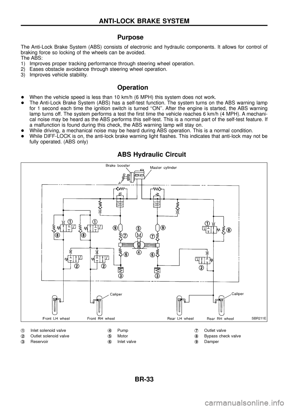
ABS Hydraulic Circuit
j1Inlet solenoid valve
j
2Outlet solenoid valve
j
3Reservoir j
4Pump
j
5Motor
j
6Inlet valve j
7Outlet valve
j
8Bypass check valve
j
9Damper
SBR211E
ANTI-LOCK BRAKE SYSTEM
BR-33
Page 36 of 75

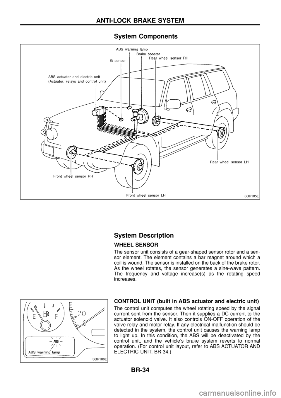
System Components
System Description
WHEEL SENSOR
The sensor unit consists of a gear-shaped sensor rotor and a sen-
sor element. The element contains a bar magnet around which a
coil is wound. The sensor is installed on the back of the brake rotor.
As the wheel rotates, the sensor generates a sine-wave pattern.
The frequency and voltage increase(s) as the rotating speed
increases.
CONTROL UNIT (built in ABS actuator and electric unit)
The control unit computes the wheel rotating speed by the signal
current sent from the sensor. Then it supplies a DC current to the
actuator solenoid valve. It also controls ON-OFF operation of the
valve relay and motor relay. If any electrical malfunction should be
detected in the system, the control unit causes the warning lamp
to light up. In this condition, the ABS will be deactivated by the
control unit, and the vehicle's brake system reverts to normal
operation. (For control unit layout, refer to ABS ACTUATOR AND
ELECTRIC UNIT, BR-34.)
SBR185E
SBR186E
ANTI-LOCK BRAKE SYSTEM
BR-34
Page 49 of 75

Self-diagnosis
FUNCTION
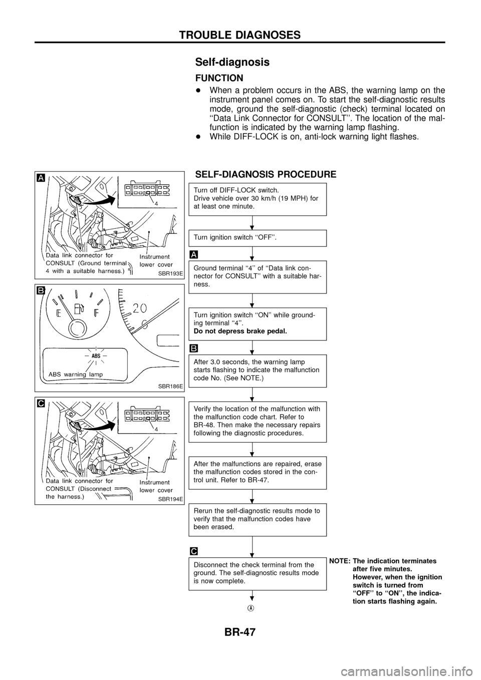
+When a problem occurs in the ABS, the warning lamp on the
instrument panel comes on. To start the self-diagnostic results
mode, ground the self-diagnostic (check) terminal located on
``Data Link Connector for CONSULT''. The location of the mal-
function is indicated by the warning lamp ¯ashing.
+ While DIFF-LOCK is on, anti-lock warning light ¯ashes.
SELF-DIAGNOSIS PROCEDURE
Turn off DIFF-LOCK switch.
Drive vehicle over 30 km/h (19 MPH) for
at least one minute.
Turn ignition switch ``OFF''.
Ground terminal ``4'' of ``Data link con-
nector for CONSULT'' with a suitable har-
ness.
Turn ignition switch ``ON'' while ground-
ing terminal ``4''.
Do not depress brake pedal.
After 3.0 seconds, the warning lamp
starts ¯ashing to indicate the malfunction
code No. (See NOTE.)
Verify the location of the malfunction with
the malfunction code chart. Refer to
BR-48. Then make the necessary repairs
following the diagnostic procedures.
After the malfunctions are repaired, erase
the malfunction codes stored in the con-
trol unit. Refer to BR-47.
Rerun the self-diagnostic results mode to
verify that the malfunction codes have
been erased.
Disconnect the check terminal from the
ground. The self-diagnostic results mode
is now complete.NOTE: The indication terminates
after ®ve minutes.
However, when the ignition
switch is turned from
``OFF'' to ``ON'', the indica-
tion starts ¯ashing again.
j
A
SBR193E
SBR186E
SBR194E
.
.
.
.
.
.
.
.
.
TROUBLE DIAGNOSES
BR-47