1998 MITSUBISHI MONTERO light
[x] Cancel search: lightPage 559 of 1501

during manufacture, some new type valves cannot be reground.
Resurface valve on proper angle specification using valve
grinding machine. Follow manufacturer's instructions for valve
grinding machine. Specifications may indicate a different valve face
angle than seat angle.
Measure valve margin after grinding. Replace valve if not
within specification. Valve stem tip can be refinished using valve
grinding machine.
Valve Lapping
During valve lapping of recent designed valves, be sure to
follow manufacturers recommendations. Surface hardening and materials
used with some valves do not permit lapping. Lapping process will
remove excessive amounts of the hardened surface.
Valve lapping is done to ensure adequate sealing between
valve face and seat. Use either a hand drill or lapping stick with
suction cup attached.
Moisten and attach suction cup to valve. Lubricate valve stem
and guide. Apply a thin coat of fine valve grinding compound between
valve and seat. Rotate lapping tool between the palms or with hand
drill.
Lift valve upward off the seat and change position often.
This is done to prevent grooving of valve seat. Lap valve until a
smooth polished seat is obtained. Thoroughly clean grinding compound
from components. Valve to valve seat concentricity should be checked.
See VALVE SEAT CONCENTRICITY.
CAUTION: Valve guides must be in good condition and free of carbon
deposits prior to valve seat grinding. Some engines contain
an induction hardened valve seat. Excessive material removal
will damage valve seats.
Valve Seat Grinding
Select coarse stone of correct size and angle for seat to be
ground. Ensure stone is true and has a smooth surface. Select correct
size pilot for valve guide dimension. Install pilot in valve guide.
Lightly lubricate pilot shaft. Install stone on pilot. Move stone off
and on the seat approximately 2 times per second during grinding
operation.
Select a fine stone to finish grinding operation. Grinding
stones with 30 and 60 degree angles are used to center and narrow the
valve seat as required. See Fig. 10.
Fig. 10: Adjusting Valve Seat Width - Typical
This Graphic For General Information Only
Valve Seat Replacement
Replacement of valve seat inserts is done by cutting out
Page 560 of 1501

the old insert and machining an oversize insert bore. Replacement
oversize insert is usually chilled and the cylinder head is sometimes
warmed. Valve seat is pressed into the head. This operation requires
specialized machine shop equipment.
Valve Seat Concentricity
Using dial gauge, install gauge pilot in valve guide.
Position gauge arm on the valve seat. Adjust dial indicator to zero.
Rotate arm 360 degrees and note reading. Runout should not exceed
specification.
To check valve-to-valve seat concentricity, coat valve face
lightly with Prussian Blue dye. Install valve and rotate it on valve
seat. If pattern is even and entire seat is coated at valve contact
point, valve is concentric with the seat.
REASSEMBLY
Valve Stem Installed Height
Valve stem installed height must be checked when new valves
are installed or when valves or valve seats have been ground. Install
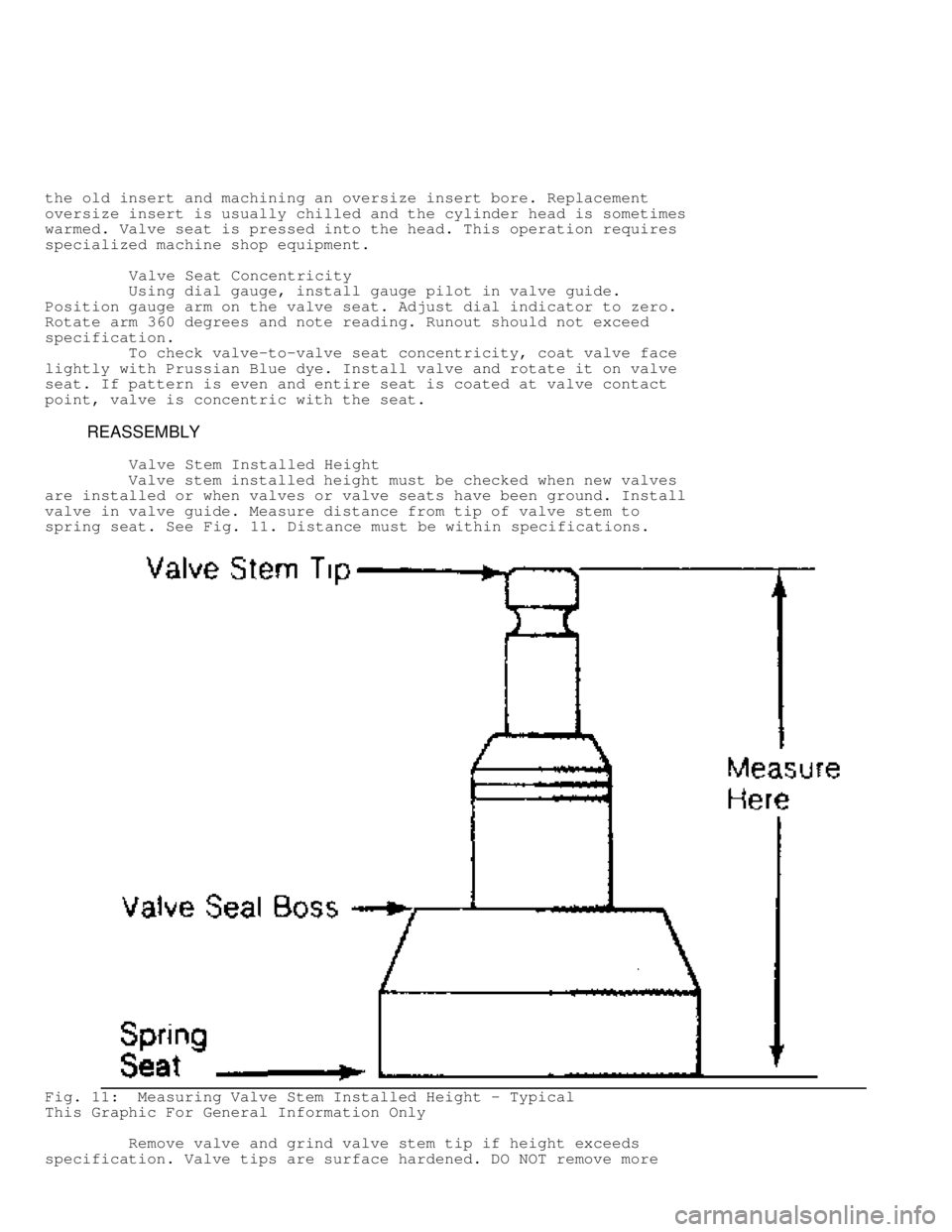
valve in valve guide. Measure distance from tip of valve stem to
spring seat. See Fig. 11. Distance must be within specifications.
Fig. 11: Measuring Valve Stem Installed Height - Typical
This Graphic For General Information Only
Remove valve and grind valve stem tip if height exceeds
specification. Valve tips are surface hardened. DO NOT remove more
Page 569 of 1501

over connecting rod bolts. Install piston and connecting rod assembly.
Ensure piston notch, arrow or "FRONT" mark is toward front of engine.
See Fig. 17 .
Fig. 17: Installing Piston & Connecting Rod Assembly - Typical
This Graphic For General Information Only
Carefully tap piston into cylinder until rod bearing is
seated on crankshaft journal. Remove protectors. Install rod cap and
bearing. Lightly tighten connecting rod bolts. Repeat procedure for
remaining cylinders. Check bearing clearance. See
MAIN & CONNECTING ROD BEARING CLEARANCE in this article.
Once clearance is checked, lubricate journals and bearings.
Install bearing caps. Ensure marks are aligned on connecting rod and
cap. Tighten rod nuts or bolts to specification. Ensure rod moves
freely on crankshaft. Check connecting rod side clearance. See
CONNECTING ROD SIDE CLEARANCE in this article.
CONNECTING ROD SIDE CLEARANCE
Position connecting rod toward one side of crankshaft as far
as possible. Using feeler gauge, measure clearance between side of
connecting rod and crankshaft. See Fig. 18. Clearance must be within
specifications.
Page 576 of 1501

length of cylinder block at several points.
If warpage exceeds specifications, deck must be resurfaced.
If warpage exceeds manufacturer's maximum tolerance for material
removal, replace block.
DECK HEIGHT
Distance from the crankshaft centerline to the block
deck is termed the deck height. Measure and record front and rear main
journals of crankshaft. To compute this distance, install crankshaft
and retain with center main bearing and cap only. Measure distance
from the crankshaft journal to the block deck, parallel to the
cylinder centerline.
Add one half of the main bearing journal diameter to distance
from crankshaft journal to block deck. This dimension should be
checked at front and rear of cylinder block. Both readings should be
the same.
If difference exceeds specifications, cylinder block must be
repaired or replaced. Deck height and warpage should be corrected at
the same time.
MAIN BEARING BORE & ALIGNMENT
For checking main bearing bore, remove all bearings from
cylinder block and main bearing caps. Install main bearing caps in
original location. Tighten bolts to specification. Using inside
micrometer, measure main bearing bore in 2 areas 90 degrees apart.
Determine bore size and out-of-round. If diameter is not within
specification, block must be align-bored.
For checking alignment, place a straightedge along centerline
of main bearing saddles. Check for clearance between straightedge and
main bearing saddles. Block must be align-bored if clearance is
present.
EXPANSION PLUG REMOVAL & INSTALLATION
Removal
Drill a hole in the center of expansion plug. Remove with
screwdriver or punch. Use care not to damage sealing surface.
Installation
Ensure sealing surface is free of burrs. Coat expansion plug
with sealer. Use a wooden dowel or pipe of slightly smaller diameter,
install expansion plug. Ensure expansion plug is evenly located.
OIL GALLERY PLUG REMOVAL & INSTALLATION
Removal
Remove threaded oil gallery plugs using the appropriate
wrench. Soft, press-in plugs are removed by drilling into plug and
installing a sheet metal screw. Remove plug with slide hammer or
pliers.
Installation
Ensure threads or sealing surface is clean. Coat threaded oil
gallery plugs with sealer and install. Replacement soft press-in plugs
are driven in place with a hammer and drift.
CAMSHAFT
* PLEASE READ THIS FIRST *
Page 583 of 1501

lightly into its seat. Using seal installer, fully seat seal in
bearing cap or cylinder block.
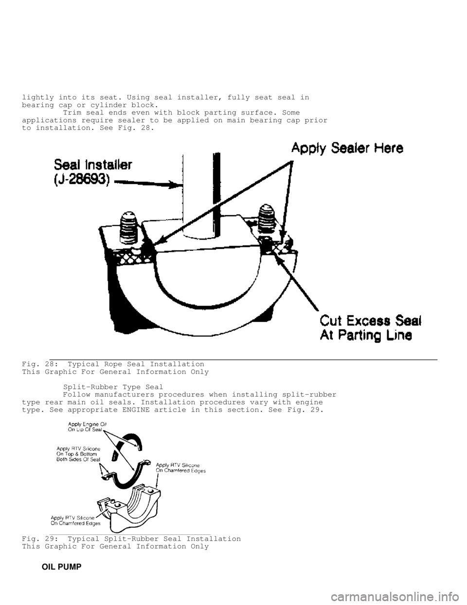
Trim seal ends even with block parting surface. Some
applications require sealer to be applied on main bearing cap prior
to installation. See Fig. 28.
Fig. 28: Typical Rope Seal Installation
This Graphic For General Information Only
Split-Rubber Type Seal
Follow manufacturers procedures when installing split-rubber
type rear main oil seals. Installation procedures vary with engine
type. See appropriate ENGINE article in this section. See Fig. 29.
Fig. 29: Typical Split-Rubber Seal Installation
This Graphic For General Information Only
OIL PUMP
Page 586 of 1501

damaged.
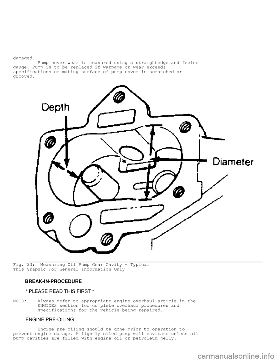
Pump cover wear is measured using a straightedge and feeler
gauge. Pump is to be replaced if warpage or wear exceeds
specifications or mating surface of pump cover is scratched or
grooved.
Fig. 33: Measuring Oil Pump Gear Cavity - Typical
This Graphic For General Information Only
BREAK-IN-PROCEDURE
* PLEASE READ THIS FIRST *
NOTE: Always refer to appropriate engine overhaul article in the
ENGINES section for complete overhaul procedures and
specifications for the vehicle being repaired.
ENGINE PRE-OILING
Engine pre-oiling should be done prior to operation to
prevent engine damage. A lightly oiled pump will cavitate unless oil
pump cavities are filled with engine oil or petroleum jelly.
Page 717 of 1501

98V220000: FRONT BRAKE LINE INSPECTION
1998 Mitsubishi Montero
NHTSA RECALL BULLETIN
Model(s): 1997-98 Mitsubishi Montero
Campaign No: 98V220000
Number of Affected Vehicles: 61800
Beginning Date of Manufacture: 1996 JUN
Ending Date of Manufacture: 1998 MAY
VEHICLE DESCRIPTION:
Sport utility vehicles.
DESCRIPTION OF DEFECT:
The front brake lines can develop pin holes due to chaffing against
the edge of the pass-through hole in the inner fender.
CONSEQUENCE OF DEFECT:
Brake fluid can leak resulting in deteriorated braking performance and
illumination of the brake indicator lamp.
CORRECTIVE ACTION:
Dealers will inspect the front brake lines for signs of wear and
routing. If the lines are not correctly centered in the pass-through
hole, the lines will be repositioned by bending slightly to correct.
If there is evidence of brake line wear, the brake line will be
replaced.
OWNER NOTIFICATION:
Owner notification is expected to begin October 19, 1998. Owners who
take their vehicles to an authorized dealer on an agreed upon service
date and do not receive the free remedy within a reasonable time
should contact Mitsubishi at 1-800-222-0037. Also contact the
National Highway Traffic Safety Administration's Auto Safety Hotline
at 1-888-dash-2-dot (1-888-327-4236).
ADDITIONAL INFORMATION:
The National Highway Traffic Safety Administration operates Monday
through Friday from 8:00 AM to 4:00 PM, Eastern Time. For more
information call (800) 424-9393 or (202) 366-0123. For the hearing
impaired, call (800) 424-9153.
Page 719 of 1501

* Load Value (Displayed As Percent)
* Engine Coolant Temperature
* Short Term Fuel Trim (Displayed As Percent)
* Long Term Fuel Trim (Displayed As Percent)
* MAP Vacuum
* Engine RPM
* Vehicle Speed Sensor
* DTC During Data Recording
SELF-DIAGNOSTIC SYSTEM
SERVICE PRECAUTIONS
Before proceeding with diagnosis, following precautions must
be observed:
* Ensure vehicle has a fully charged battery and functional
charging system.
* Visually inspect connectors and circuit wiring being worked
on.
* DO NOT disconnect battery or PCM. This will erase any DTCs
stored in PCM.
* DO NOT cause short circuits when performing electrical tests.
This will set additional DTCs, making diagnosis of original
problem more difficult.
* DO NOT use a test light in place of a voltmeter.
* When checking for spark, ensure coil wire is NOT more than
1/4" from chassis ground. If coil wire is more than 1/4" from
chassis ground, damage to vehicle electronics and/or PCM may
result.
* DO NOT prolong testing of fuel injectors. Engine may
hydrostatically (liquid) lock.
* When a vehicle has multiple DTCs, always repair lowest number
DTC first.
VISUAL INSPECTION
Most driveability problems in the engine control system
result from faulty wiring, poor electrical connections or leaking air
and vacuum hose connections. To avoid unnecessary component testing,
perform a visual inspection before beginning self-diagnostic tests.
ENTERING ON-BOARD DIAGNOSTICS
NOTE: DO NOT skip any steps in self-diagnostic tests or incorrect
diagnosis may result. Ensure self-diagnostic test applies to
vehicle being tested.
DTCs may be retrieved by using a scan tool only. Proceed to
DTC retrieval method.
NOTE: Although other scan tools are available, Mitsubishi
recommends using Multi-Use Tester II (MUT II) scan tool.
Using Scan Tool
1) Refer to manufacturer's operation manual for instructions
in use of scan tool. Before entering on-board diagnostics, see
SERVICE PRECAUTIONS . Locate Data Link Connector (DLC) under instrument
panel, near steering column.
2) Turn ignition switch to OFF position. Connect scan tool to
DLC. Turn ignition switch to ON position. Read and record scan tool
self-diagnostic output. Proceed to TROUBLE CODE DEFINITION.