Page 820 of 2490
Engine - Secondary Timing Chain Tensioner RH4.0L NA V8 - AJ27
In-vehicle Repair
Removal
Special Tool(s)
Camshaft setting
303-530
Crankshaft setting
303-531
Timing chain tensioning
303-532 1. Open the engine compartment and fit paintwork protection
sheets.
2. Disconnect the batt ery ground cable.
Remove the battery cover.
3. Remove the Cam Cover from Ba nk 1. Refer to Operation
12.29.44.
4. Raise the vehicle on a ramp.
5. Remove the crankshaft position sensor.
1. Remove the bolt which secures the crankshaft position sensor to the flywheel housing.
Remove the sensor and allow it to hang free under the
engine.
2. Remove the access grommet (for torque converter bolts) from the housing.
Page 825 of 2490
Engine - Secondary Timing Chain Tensioner RH4.0L SC V8 - AJ26/3.2L NA
V8 - AJ26, 3.2L/4.0L
In-vehicle Repair
Removal
Special Tool(s)
Camshaft setting
303-530
Crankshaft setting
303-531
Timing chain tensioning
303-532
1. Open the engine compartment and fit paintwork protection
sheets.
2. Disconnect the batt ery ground cable.
Remove the battery cover.
3. Remove the Cam Cover from Ba nk 1. Refer to Operation
12.29.44.
4. Raise the vehicle on a ramp.
5. Remove the crankshaft position sensor.
1. Remove the bolt which secures the crankshaft position sensor to the flywheel housing.
Remove the sensor and allow it to hang free under the
engine.
2. Remove the access grommet (for torque converter bolts) from the housing.
Page 836 of 2490
3. Install and tighten the bolts to 11-13 Nm.
7. Install the oil pan gasket to the oil pan body assembly.
Insert the seal into the locating positions in the groove,
working around from a corner.
Press in the remainder of th e seal, following the same
procedure.
8. Install the oil pan to the oil pan body.
1. Position and align the oil pan.
2. Install, but do not tighte n, all eighteen bolts which
secure the oil pan.
9. Tighten the bolts to the correct torque figure 11-13 Nm, in the
sequence indicated.
Tighten the drain plug to 30-40 Nm.
10. Install the oil pressure switch.
For additional information, refer to Oil Pressure Switch
- in this
section.
11. NOTE: Apply a suitable amount of clean engine oil to lubricate
the oil filter O-ring seal.
Using the special tool, install the oil filter.
Page 845 of 2490
3. Install and tighten the bolts to 11-13 Nm.
7. Install the oil pan gasket to the oil pan body assembly.
Insert the seal into the locating positions in the groove,
working around from a corner.
Press in the remainder of th e seal, following the same
procedure.
8. Install the oil pan to the oil pan body.
1. Position and align the oil pan.
2. Install, but do not tighte n, all eighteen bolts which
secure the oil pan.
9. Tighten the bolts to the correct torque figure 11-13 Nm, in the
sequence indicated.
Tighten the drain plug to 30-40 Nm.
10. Install the oil pressure switch.
For additional information, refer to Oil Pressure Switch
- in this
section.
11. NOTE: Apply a suitable amount of clean engine oil to lubricate
the oil filter O-ring seal.
Using the special tool, install the oil filter.
Page 855 of 2490
3. Install and tighten the bolts to 11-13 Nm.
7. Install the oil pick-up pipe.
1. Install a new O-ring se al to the pick-up pipe.
2. Lubricate the O-ring seal with clean engine oil and install the pipe to the oil pan body.
3. Install and tighten the bolts to 11-13 Nm.
8. Install the oil pan gasket to the oil pan body assembly.
Insert the seal into the locating positions in the groove,
working around from a corner.
Press in the remainder of th e seal, following the same
procedure.
9. Install the oil pan to the oil pan body.
1. Position and align the oil pan.
2. Install, but do not tighte n, all eighteen bolts which
secure the oil pan.
10. Tighten the bolts to the correct torque figure 11-13 Nm, in
the sequence indicated.
Tighten the drain plug to 30-40 Nm.
Page 880 of 2490

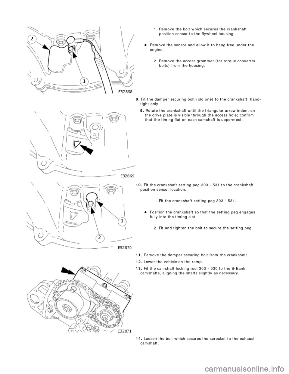
1. Remove the bolt which secures the crankshaft position sensor to the flywheel housing.
Remove the sensor and allow it to hang free under the
engine.
2. Remove the access grommet (for torque converter bolts) from the housing.
8. Fit the damper securing bolt (old one) to the crankshaft, hand-
tight only.
9. Rotate the crankshaft until the triangular arrow indent on
the drive plate is visible thro ugh the access hole; confirm
that the timing flat on ea ch camshaft is uppermost.
10. Fit the crankshaft setting peg 303 - 531 to the crankshaft
position sensor location.
1. Fit the crankshaft setting peg 303 - 531.
Position the crankshaft so that the setting peg engages
fully into the timing slot.
2. Fit and tighten the bolt to secure the setting peg.
11. Remove the damper securing bolt from the crankshaft.
12. Lower the vehicle on the ramp.
13. Fit the camshaft locking tool 303 - 530 to the B-Bank
camshafts, aligning the shafts slightly as necessary.
14. Loosen the bolt which secures the sprocket to the exhaust
camshaft.
Page 886 of 2490

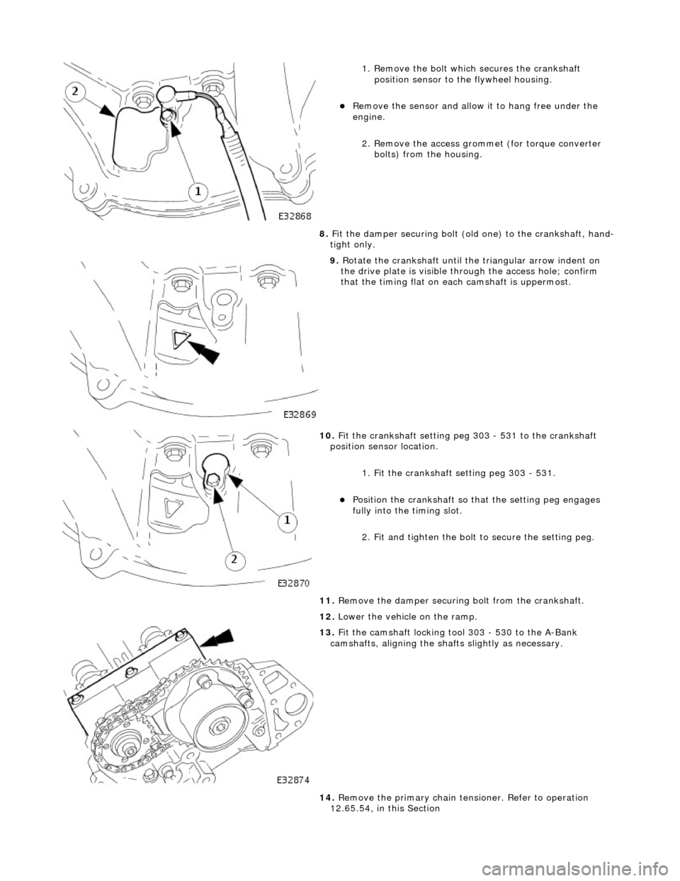
1. Remove the bolt which secures the crankshaft position sensor to the flywheel housing.
Remove the sensor and allow it to hang free under the
engine.
2. Remove the access grommet (for torque converter bolts) from the housing.
8. Fit the damper securing bolt (old one) to the crankshaft, hand-
tight only.
9. Rotate the crankshaft until the triangular arrow indent on
the drive plate is visible thro ugh the access hole; confirm
that the timing flat on ea ch camshaft is uppermost.
10. Fit the crankshaft setting peg 303 - 531 to the crankshaft
position sensor location.
1. Fit the crankshaft setting peg 303 - 531.
Position the crankshaft so that the setting peg engages
fully into the timing slot.
2. Fit and tighten the bolt to secure the setting peg.
11. Remove the damper securing bolt from the crankshaft.
12. Lower the vehicle on the ramp.
13. Fit the camshaft locking tool 303 - 530 to the A-Bank
camshafts, aligning the shafts slightly as necessary.
14. Remove the primary chain tens ioner. Refer to operation
12.65.54, in this Section
Page 912 of 2490
Align th
e engine front mountings and fit the securing nuts.
Tighte
n to the stated torque value.
3. Operate the crane controls and the ramp simultaneously (with
assistance) to raise the vehicle to a convenient working height.
4. Po
sition the transmission jack and raise it to take the weight of
the transmission. Fit and adjust the chains to secure the
transmission to the jack.
5. Fit th
e engine rear mounting bracket.
Fi
t the four bolts which secu
re the crossmember to the
body.
Fi t t
he bolt which secures the
engine rear mounting rubber
to the transmission.
6. Tigh ten th
e rear mounting bolts
to the stated torque figure.
7. Release and remove the transmission jack.
8. Operate the crane controls and the ramp simultaneously (with
assistance) to lower the vehicle to a convenient working height.
9. Lower th e cran
e and remove th
e chain assembly and lifting
eyes.