Page 1277 of 2490

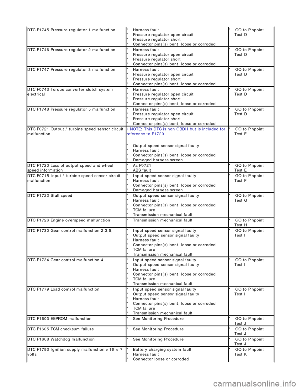
DTC P1745 Pressure regulator 1 malfunctionHarness fault
Pressure regulator open circuit
Pressure regulator short
Connector pins(s) bent, loose or corroded
*
*
*
*GO to Pinpoint
Test D
*
DTC P1746 Pressure regulator 2 malfunctionHarness fault
Pressure regulator open circuit
Pressure regulator short
Connector pins(s) bent
, loose or corroded
*
*
*
*GO to Pinpoint
Test D
*
DTC P1747 Pressure regulator 3 malfunctionHarness fault
Pressure regulator open circuit
Pressure regulator short
Connector pins(s) bent
, loose or corroded
*
*
*
*GO to Pinpoint
Test D
*
DTC P0743 Torque converter clutch system
electricalHarness fault
Pressure regulator open circuit
Pressure regulator short
Connector pins(s) bent
, loose or corroded
*
*
*
*GO to Pinpoint
Test D
*
DTC P1748 Pressure regulator 5 malfunctionHarness fault
Pressure regulator open circuit
Pressure regulator short
Connector pins(s) bent
, loose or corroded
*
*
*
*GO to Pinpoint
Test D
*
DTC P0721 Output / turbine speed sensor circuit
malfunction• NOTE: This DTC is non OBDII but is included for
reference to P1720
Output speed sensor signal faulty
Harness fault
Connector pins(s) bent , loose or corroded
Damaged harness screen
*
*
*
*GO to Pinpoint
Test E
*
DTC P1720 Loss of output speed and wheel
speed informationAs P0721
ABS fault
*
*GO to Pinpoint
Test E
*
DTC P0715 Input / turbine speed sensor circuit
malfunctionInput speed sensor signal faulty
Harness fault
Connector pins(s) bent
, loose or corroded
Damaged harness screen
*
*
*
*GO to Pinpoint
Test F
*
DTC P1722 Stall speedOutput speed sensor signal faulty
Harness fault
Connector pins(s) bent
, loose or corroded
TCM failure
Transmission mechanical fault
*
*
*
*
*GO to Pinpoint
Test G
*
DTC P1726 Engine overspeed malfunctionTransmission mechanical fault
*GO to Pinpoint
Test H
*
DTC P1730 Gear control malfunction 2,3,5,Input speed sensor signal faulty
Output speed sensor signal faulty
Harness fault
Connector pins(s) bent
, loose or corroded
TCM failure
Transmission mechanical fault
*
*
*
*
*
*GO to Pinpoint
Test I
*
DTC P1734 Gear control malfunction 4Input speed sensor signal faulty
Output speed sensor signal faulty
Harness fault
Connector pins(s) bent
, loose or corroded
TCM failure
Transmission mechanical fault
*
*
*
*
*
*GO to Pinpoint
Test I
*
DTC P1779 Load control malfunctionInput speed sensor signal faulty
Output speed sensor signal faulty
Harness fault
Connector pins(s) bent
, loose or corroded
TCM failure
Transmission mechanical fault
*
*
*
*
*
*GO to Pinpoint
Test I
*
DTC P1603 EEPROM malfunctionSee Monitoring Procedure
*GO to Pinpoint
Test J
*
DTC P1605 TCM checksum failureSee Monitoring Procedure
*GO to Pinpoint
Test J
*
DTC P1608 Watchdog malfunctionSee Monitoring Procedure
*GO to Pinpoint
Test J
*
DTC P1793 Ignition supply malfunction >16 < 7
voltsBattery charging system fault
Harness fault
Connector loose or corroded
*
*
*GO to Pinpoint
Test K
*
Page 1278 of 2490

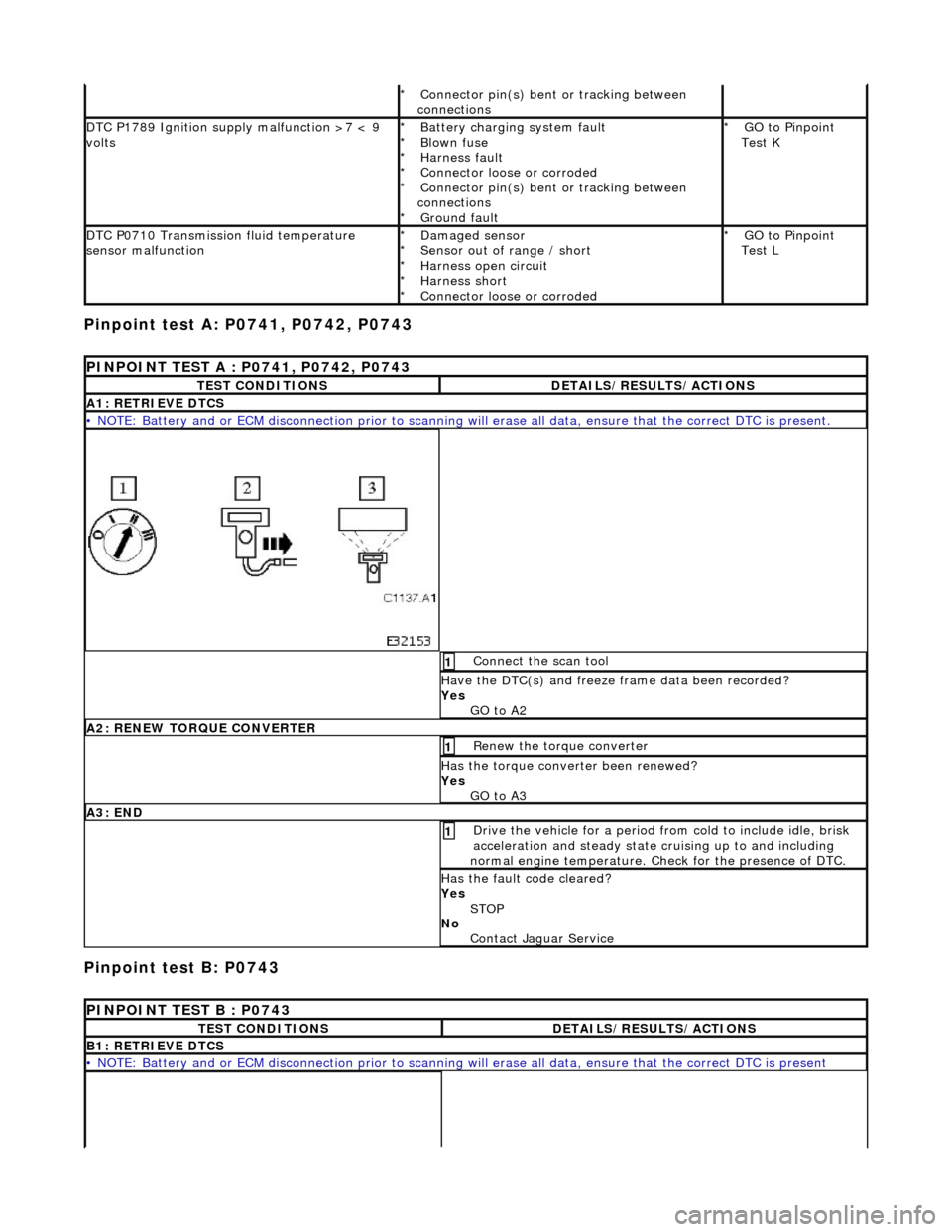
Pinpoint test A: P0741, P0742, P0743
Pinpoint test B: P0743
Connector pin(s) bent or tracking between
connections
*
DTC P1789 Ignition supply malfunction >7 < 9
voltsBattery charging system fault
Blown fuse
Harness fault
Connector loose or corroded
Connector pin(s) bent or tracking between
connections Ground fault
*
*
*
*
*
*GO to Pinpoint
Test K
*
DTC P0710 Transmission fluid temperature
sensor malfunctionDamaged sensor
Sensor out of range / short
Harness open circuit
Harness short
Connector loose or corroded
*
*
*
*
*GO to Pinpoint
Test L
*
PINPOINT TEST A : P0741, P0742, P0743
TEST CONDITIONSDETAILS/RESULTS/ACTIONS
A1: RETRIEVE DTCS
• NOTE: Battery and or ECM disconnection prior to scanning wi
ll erase all data, ensure that the correct DTC is present.
Connect the scan tool 1
Have the DTC(s) and freeze frame data been recorded?
Yes GO to A2
A2: RENEW TORQUE CONVERTER
Renew the torque converter 1
Has the torque converter been renewed?
Yes GO to A3
A3: END
Drive the vehicle for a period from cold to include idle, brisk
acceleration and steady state cruising up to and including
normal engine temperature. Check for the presence of DTC. 1
Has the fault code cleared?
Yes STOP
No Contact Jaguar Service
PINPOINT TEST B : P0743
TEST CONDITIONSDETAILS/RESULTS/ACTIONS
B1: RETRIEVE DTCS
• NOTE: Battery and or ECM disconnection prior to scanning wi ll erase all data, ensure that the correct DTC is present
Page 1335 of 2490
Automatic Transmission/Transaxle - 4.0L NA V8 - AJ27/3.2L NA V8 - AJ26
- Transmission Fluid Drain and Refill
General Procedures
Removal
Installation
Special Tool(s)
Syringe 1. Raise the vehicle for access.
2. NOTE: This procedure will not re move residual fluid from the
torque converter.
Drain the transmission fluid.
2. WARNING: TRANSMISSION FLUID MAY CAUSE
SEVERE BURNS, ENSURE THAT ALL SAFETY PROCEDURES
ARE OBSERVED AND THAT THE RECEPTACLE FOR WASTE
HAS SUFFICIENT CAPACITY.
Carefully remove the drain plug and drain the
transmission fluid.
3. Refit the drain plug and tighten to the specified torque figure.
Use a new O-ring.
1. Remove the fluid level / filler plug.
2. Using a syringe dedicated to tran smission fluid only (not used
for any other type of oil or fluids ), inject transmission fluid until
Page 1337 of 2490
8. Cycle the gear selector.
From P to D.
From D to R.
From R to P.
9. From below.
10. Adjust the transmission fluid level.
1. Remove the filler / level plug.
2. Inject fluid until it ove rflows from the plug orifice.
10. CAUTION: The fluid temperature MUST NOT
exceed 50°C.
Wait for the flow of fluid to re duce to a trickle (for at least
1 minute).
11. Refit the filler / level plug and tighten to the specified torque
figure.
Page 1340 of 2490
Installation
6. Remove the nine screws from th e pressure regulator / solenoid
retaining plate.
7. Remove the relevant pressure regulator.
1. Installation is the reverse of the removal procedure, noting
that a new pressure regulator 'O' ring MUST be used.
Fit the nine screws securing the pressure regulator /
solenoid retaining plate and ti ghten to the specified torque
figure.
2. Refit the RH rear valve body secu ring screws and tighten to the
specified torque figure.
Page 1341 of 2490
3. NOTE: Ensure extreme clea nliness and never reuse
transmission fluid.
Using a new gasket, install the fl uid pan and tighten the fixings
to the specified torque figure.
4. Connect the battery and fit the battery cover..
Reset the radio and the clock.
5. Refer to (44.24.02) for fluid fill procedure.
Page 1344 of 2490
Hold the housing assembly in a vice with soft jaws fitted
and carefully insert the coupling.
Fit tool 205 - 053 to the coupling.
3. Use tool 307 - 356 to tighten th e coupling nut to the specified
torque figure.
4. Stake the coupling nut at two positions.
5. Refit the rear extension housing. Refer to Operation 44.20.19.
6. Check the transmission fluid level. Refer to Operation
44.24.02.
Page 1346 of 2490
Installation
9. Clean the mating faces.
1. Installation is the reverse of the removal procedure noting
that;
1. Install a new O-ring seal.
2. Tighten the ten bolts to the specified torque figure.
2. Align the driveshaft with the tr ansmission drive flange using
the marks made on removal.
Tighten the three bolts to the specified torque figure.
3. Raise the transmission carefu lly to position, using the
transmission jack
4. Fit the engine rear mounting and tighten the centre bolt and
outer bolts to the specified torque figures.
Check that the safety chain on the transmission jack will
not be trapped when the mounting is fitted.
5. Remove the transmission jack.