Page 1808 of 2490

Air Conditioning - Condenser Core
Removal and Installation
Removal
1. Disconnect battery ground cable (IMPORTANT, see SRO
86.15.19 for further information).
2. Drain radiator coolant only; refer to 26.10.01 or (SC)
26.10.01.
3. Recover refrigerant from air co nditioning system; refer to
82.30.30.
4. Release both gas struts, set the engine cover fully forward to
the service access position an d support with a wooden (or
similar) strut.
5. CAUTION: Take care not to damage hood or radiator
grille.
Remove twin fan and motor as sembly; refer to 26.25.12.
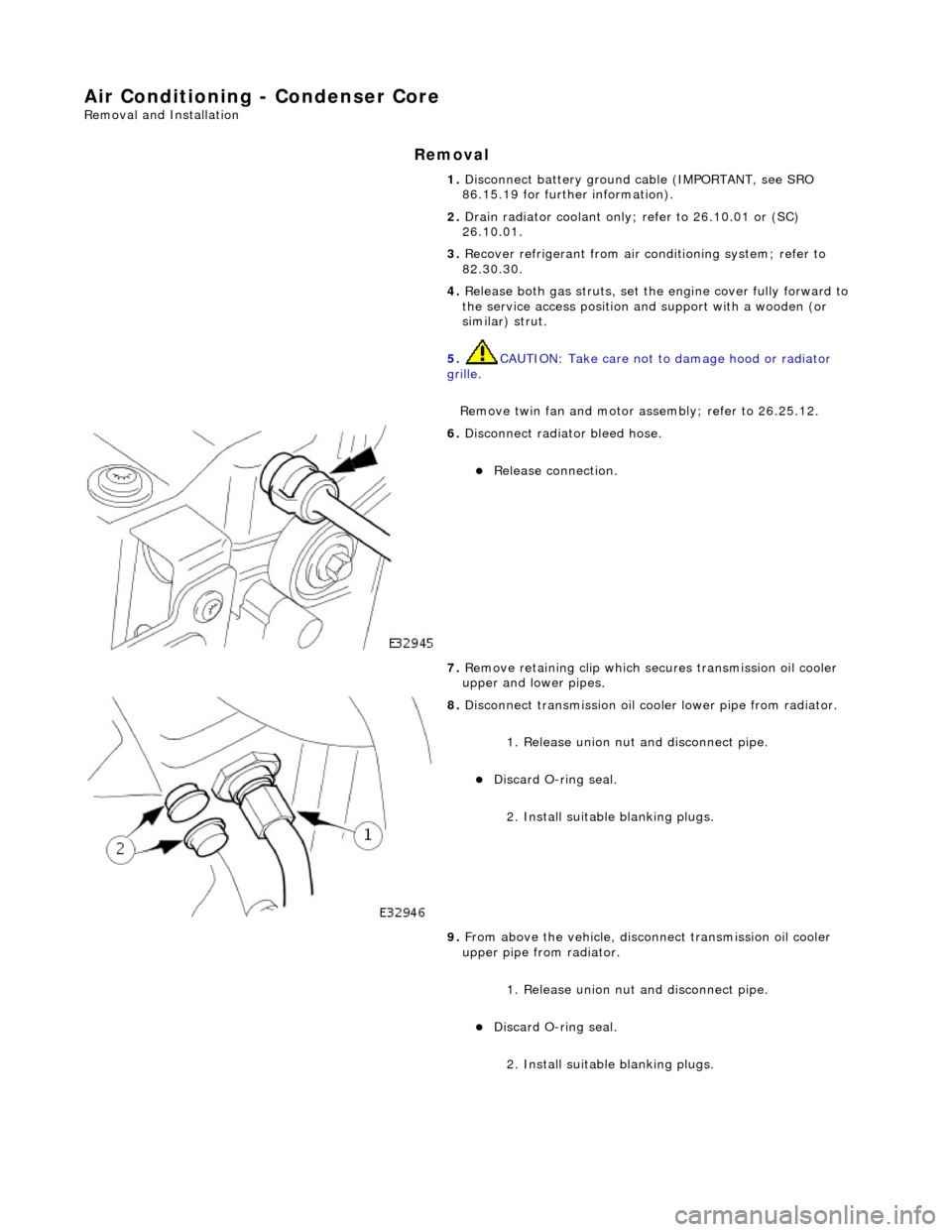
6. Disconnect radiator bleed hose.
Release connection.
7. Remove retaining clip which secures transmission oil cooler
upper and lower pipes.
8. Disconnect transmission oil cooler lower pipe from radiator.
1. Release union nut and disconne ct pipe.
Discard O-ring seal.
2. Install suitable blanking plugs.
9. From above the vehicle, discon nect transmission oil cooler
upper pipe from radiator.
1. Release union nut and disconne ct pipe.
Discard O-ring seal.
2. Install suitable blanking plugs.
Page 1858 of 2490
In
stallation
8.
Slac ken an
d remove four screws securing major gauge
module/surround to fascia and withdraw surround.
9. With draw major gau
ge module fo
r access, disconnect the two
harness multiplugs and remove gauge module from fascia.
1. Position major gauge module in fascia and connect both
harness multiplugs.
2. Position major gauge surround on panel, routing harness
multiplugs through apertures.
3. Fit and tighten screws securing major gauge module/surround
to fascia.
4. Connect harness multiplug to tr ip keyboard and fit and fully
seat keyboard in gauge surround, ensuring correct location of
retaining tangs
5. Connect harness multiplug to fog lamp switch and fit and fully
seat switch in gaug e surround, ensuring correct location of
tangs.
6. Fit veneer panel. Refer to 76.47.24.
7. Connect ground cable to battery terminal and fit battery cover.
Refer to 86.15.15.
8. Return steering column to original position.
Page 1877 of 2490
Battery, Mounting and Cables - Battery Connect
General Procedures
1.
NOTE: Whether one, or both, cables are disconnected, a
minimum of 30 seconds MUST elapse between disconnection of
the FIRST cable and reconnection of the LAST cable. A clean final
connection must be made; do not allow temporary contact.
Connect the batter y terminal(s).
2. Reset the clock.
3. Enter the radio security code. If necessary, refer to the Sound
System Handbook.
Page 1878 of 2490
Battery, Mounting and Cables - Battery
Removal and Installation
Removal
Installation
1.
Remove the luggage compartment floor panel (when standard
size spare wheel is supplied) and the cover from the battery.
2. Disconnect the battery cables.
Disconnect the ground cable. Disconnect the positive cable.
1. Disconnect the vent pipe.
3. Remove the battery.
1. Remove the two bolts which secure the battery clamp.
2. Remove the clamp.
3. Remove the battery.
1. Installation is the reverse of removal.
2. Perform the Battery Reconnection Procedure described in this
section.
Page 1881 of 2490
Battery, Mounting and Cables - Battery Retaining Bracket
Removal and Installation
Removal
Installation
1.
Remove the luggage compartment floor panel (when standard
size spare wheel is supplied) and the cover from the battery.
2. Disconnect the battery terminal ground cable.
3. Remove the battery hold-down clamp.
1. Remove the two bolts which secure the battery hold-down clamp.
2. Remove the hold-down clamp.
1. Installation is the reverse of removal.
2. Perform the Battery Reconnection Procedure described in this
section.
Page 1882 of 2490

Generator and Regulator - Generator
Description and Operation
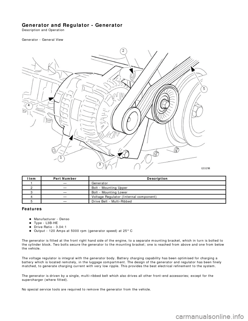
Generator - General View
Features
Manufacturer - Denso Type - L3B-HE Drive Ratio - 3.04:1 Output - 120 Amps at 5000 rpm (generator speed) at 25° C
The generator is fitted at the front right hand side of the engine, to a sepa rate mounting bracket, which in turn is bolted to
the cylinder block. Two bolts secure th e generator to the mounting bracket; one is reached from above and one from below
the vehicle.
The voltage regulator is integral with th e generator body. Battery charging capabi lity has been optimised for charging a
battery which is located remotely, in the luggage compartment. The design of the generator and regulator has been finely
matched, to generate charging current with very low ripple. This provides the best electrical refinement to the system.
The generator is driven by a single, multi-ribbed belt which also drives all other front-e nd accessories; except for the
supercharger (where fitted).
No special service tools are required to remove the generator from the vehicle.
ItemPart NumberDescription
1—Generator
2—Bolt - Mounting Upper
3—Bolt - Mounting Lower
4—Voltage Regulator (Internal component)
5—Drive Belt - Multi-Ribbed
Page 1885 of 2490

If the field were not controlled, the 'B+' output would rise to a level which could damage bulbs and ECMs. The regulator
compares the output voltage to an intern al voltage reference circuit to achieve the controlled output of the generator.
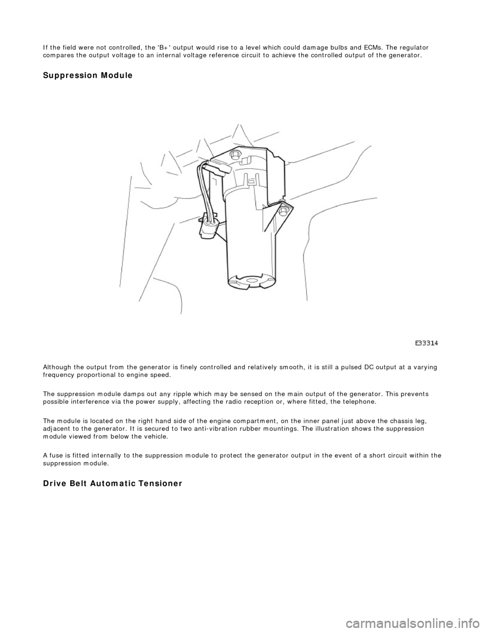
Suppression Module
Although the output from the generator is fi nely controlled and relatively smooth, it is still a pulsed DC output at a varying
frequency proportional to engine speed.
The suppression module damps ou t any ripple which may be sensed on the main output of the generator. This prevents
possible interference via the power supply, affecting the radio reception or, where fitted, the telephone.
The module is located on the right hand side of the engine compartment, on the inner panel just above the chassis leg,
adjacent to the generator. It is secured to two anti-vibration rubber moun tings. The illustration shows the suppression
module viewed from below the vehicle.
A fuse is fitted internally to the suppression module to protect the generator output in the event of a short circuit within th e
suppression module.
Drive Belt Automatic Tensioner
Page 1891 of 2490
suppression module positive cable from the positive
terminal.
3. Where fitted, remove the nut which secures the
suppression module negati ve cable and disconnect
the cable from the generator. Reposition the
suppression module harness clear of the generator.
9. Remove the lower mounting bolt and reposition the harness
mounting bracket.
10. Remove the upper securing bolt and withdraw the generator
from the mounting bracket.
11. Carefully, manoeuvre the ge nerator forward towards the
radiator.
12. Change the position of the ge nerator and remove it upwards
between the engine and the radiator.