Page 1967 of 2490
Interior Lighting - Door Courtesy Lamp Lens
Removal and Installation
Removal
Installation
1. Using a thin plastic bl ade, carefully release lens retaining tang
from guard lamp assembly.
2. Withdraw lens from gu ard lamp assembly.
1. Position lens on guard lamp assembly.
2. Press lens firmly to fully seat securing tang in guard lamp
assembly..
Page 1970 of 2490
Interior Lighting - Vanity Mirror Lamp
Removal and Installation
Removal
Installation
1.
Release sun visor from retention bezel to isolate from electrical
supply.
2. Move sun visor to downward position and turn mirror cover
upwards.
3. Using a small screwdriver, carefu lly release illumination lens
tangs from vanity assembly.
4. Supporting vanity assembly, sl acken and remove securing
screws and remove assembly from sun visor.
1. Ensure that bulb holders and sw itch contactors are correctly
positioned and seated.
2. Position and fully seat vanity as sembly on sun visor and fit and
tighten securing screws.
3. Fit and fully seat mirror illumination lenses.
4. Turn mirror cover downwards.
5. Reposition sun visor in retentio n bezel and return to upward
position.
Page 1975 of 2490

Location of J1962 socket
The J1962 socket is located at the driver side inboard footwell.
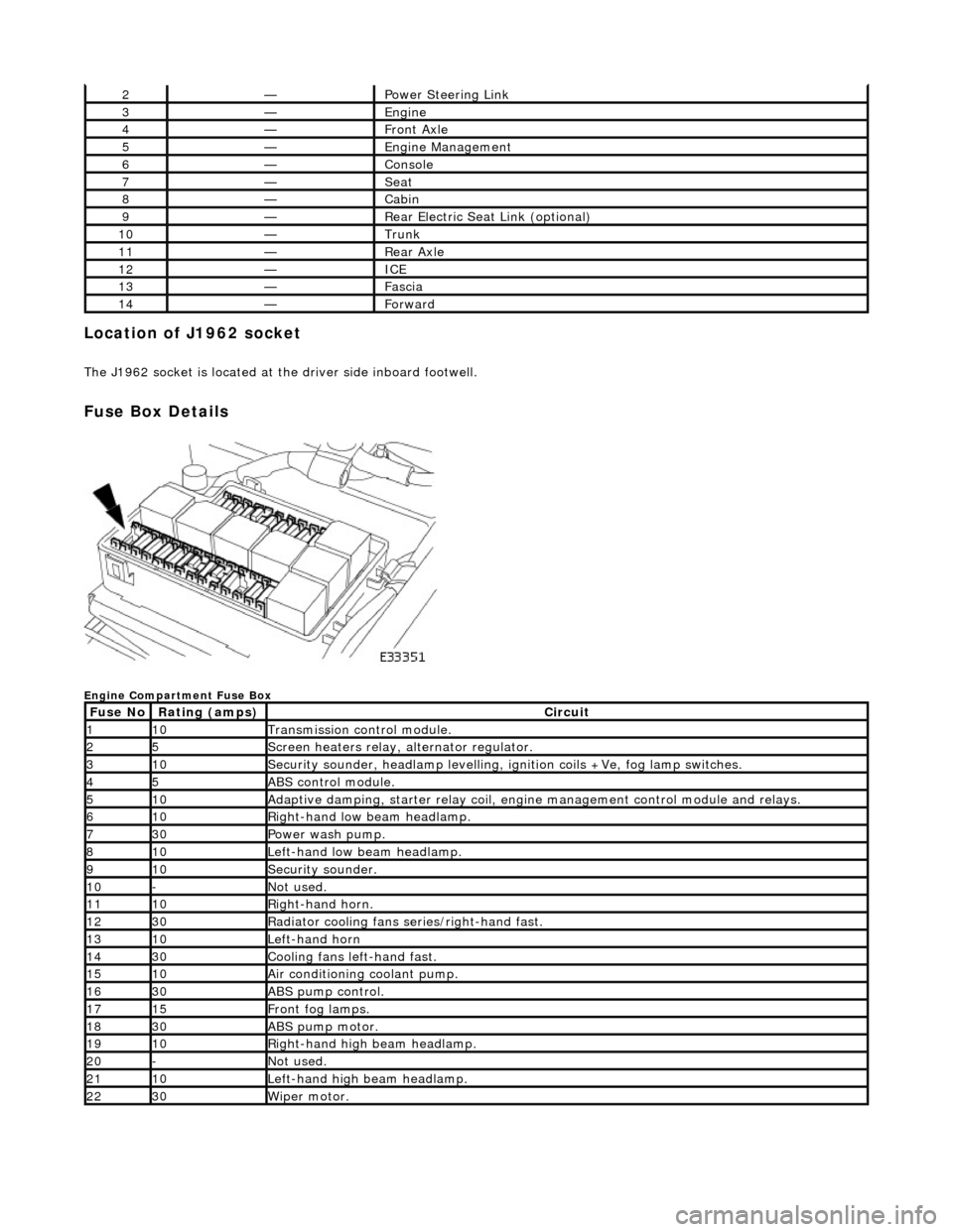
Fuse Box Details
Engine Compartment Fuse Box
2—Power Steering Link
3—Engine
4—Front Axle
5—Engine Management
6—Console
7—Seat
8—Cabin
9—Rear Electric Seat Link (optional)
10—Trunk
11—Rear Axle
12—ICE
13—Fascia
14—Forward
Fuse NoRating (amps)Circuit
110Transmission control module.
25Screen heaters relay, alternator regulator.
310Security sounder, headlamp levelling, ignition coils +Ve, fog lamp switches.
45ABS control module.
510Adaptive damping, starter relay coil, engine management control module and relays.
610Right-hand low beam headlamp.
730Power wash pump.
810Left-hand low beam headlamp.
910Security sounder.
10-Not used.
1110Right-hand horn.
1230Radiator cooling fans series/right-hand fast.
1310Left-hand horn
1430Cooling fans left-hand fast.
1510Air conditioning coolant pump.
1630ABS pump control.
1715Front fog lamps.
1830ABS pump motor.
1910Right-hand high beam headlamp.
20-Not used.
2110Left-hand high beam headlamp.
2230Wiper motor.
Page 1978 of 2490

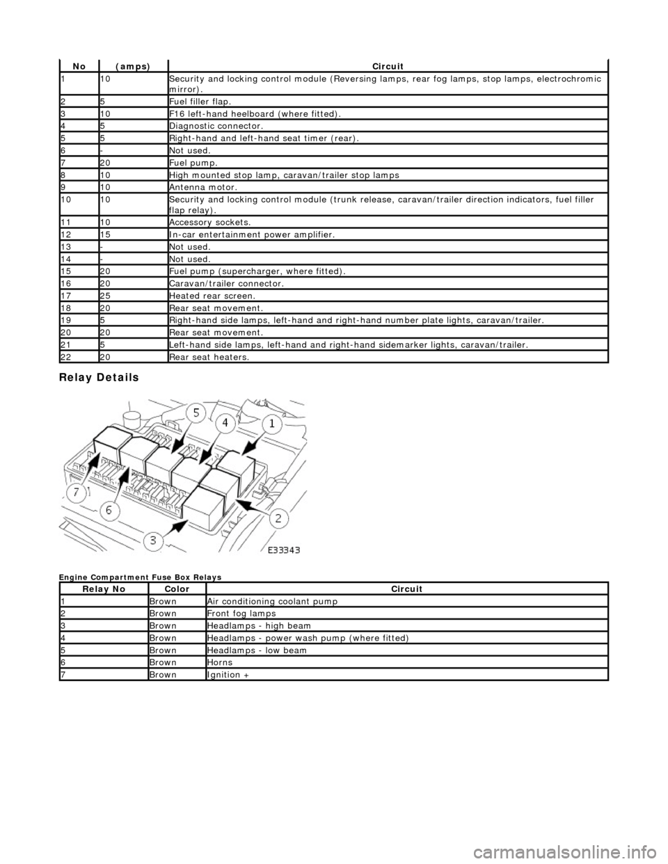
Relay Details
Engine Compartment Fuse Box Relays
No(amps)Circuit
110Security and locking control module (Reversing lamps, rear fog lamps, stop lamps, electrochromic
mirror).
25Fuel filler flap.
310F16 left-hand heelboard (where fitted).
45Diagnostic connector.
55Right-hand and left-han d seat timer (rear).
6-Not used.
720Fuel pump.
810High mounted stop lamp, caravan/trailer stop lamps
910Antenna motor.
1010Security and locking control module (trunk release, caravan/trailer direction indicators, fuel filler
flap relay).
1110Accessory sockets.
1215In-car entertainment power amplifier.
13-Not used.
14-Not used.
1520Fuel pump (supercharger, where fitted).
1620Caravan/trailer connector.
1725Heated rear screen.
1820Rear seat movement.
195Right-hand side lamps, left-h and and right-hand number pl ate lights, caravan/trailer.
2020Rear seat movement.
215Left-hand side lamps, left-hand and right-hand sidemarker lights, caravan/trailer.
2220Rear seat heaters.
Relay NoColorCircuit
1BrownAir conditioning coolant pump
2BrownFront fog lamps
3BrownHeadlamps - high beam
4BrownHeadlamps - power wash pump (where fitted)
5BrownHeadlamps - low beam
6BrownHorns
7BrownIgnition +
Page 1982 of 2490
Module Communications Network - Battery Junction Box (BJB)
Removal and Installation
Removal
1. Disconnect battery ground cable; refer to 86.15.19.
2. Remove cover from fuse box.
1. Release securing tangs.
2. Remove cover.
3. Remove positive supply power cable.
1. Displace cover.
2. Remove nut.
3. Disconnect cable.
4. Displace fuse box from mounting panel for access.
1. Release securing latch, upwards.
Release fuse box from mountin g panel by displacement
towards spare wheel.
5. Remove fuse box.
1. Identify and disconne ct harness connectors.
Page 1984 of 2490
Module Communications Network - Central Junction Box (CJB) Removal and Installation
Removal
Installation
1. Disconnect battery ground cable; refer to 86.15.19.
2. Remove heelboard trim panel.
3. Remove positive supply power cable and displace fuse box.
1. Displace cover.
Remove nut which secures posi tive cable to fuse box.
2. Disconnect cable.
3. Remove nuts.
4. Remove fuse box.
Identify and disconnect harness connectors.
5. Remove fuses and relay.
1. Remove relay.
2. Identify each fuse and remove them.
The value and position of each fuse is illustrated on the lid of the
trunk compartment fuse box - for all fuse boxes on the vehicle.
1. Installation is reverse of removal.
2. Reconnect battery ground cable; refer to 86.15.15.
Page 1985 of 2490
Module Communications Network - Front Auxiliary Junction Box
Removal and Installation
Removal
1. Disconnect battery ground cable; refer to 86.15.19.
2. Open bonnet and fit body pa intwork protection sheets.
3. Remove positive supply power cable.
1. Displace cover.
2. Remove nut.
3. Disconnect cable.
4. Remove fuse box fro m mounting panel.
1. Release securing latch, upwards, displace fuse box
outwards and remove from mounting panel.
2. Release securing tangs and remove cover.
5. Remove fuse box.
1. Identify and disconne ct harness connectors.
6. Remove fuses and relays.
Page 1988 of 2490
Installation
1. Release securing tangs and remove cover.
2. Remove relay.
3. Identify each fuse and remove them.
The value and position of each fuse is illustrated on the lid
of the trunk compartment fuse box - for all fuse boxes on
the vehicle.
1. Installation is reverse of removal.
2. Reconnect battery ground cable; refer to 86.15.15.