Page 2198 of 2490
Glass, Frames and Mechanisms - Rear Door Window Regulator Motor
Removal and Installation
Removal
Installation
1.
Remove lift motor and regulator assembly from door. Refer to
86.25.09.
2. Slacken and remove th ree screws securing motor to regulator.
3. Remove lift motor from regulator.
1. Position lift motor on regulator and fit and tighten securing
screws.
2. Fit lift motor and regulator assembly in door. Refer to
86.25.09.
Page 2199 of 2490
Glass, Frames and Mechanisms - Rear Door Window Control Switch
Removal and Installation
Removal
Installation
1.
Remove casing/armrest asse mbly from door. Refer to
76.34.04.
2. Remove armrest from casing. Refer to 76.34.23.
3. Position armrest for access, slacken and remove two
switchpack securing screws and remove switchpack assembly from armrest.
4. Slacken and remove screws securing veneer panels to switch
and ashtray.
1. Position veneer panels on sw itch and ashtray, and fit and
tighten securing screws.
2. Position switch/ashtray assembly on armrest and fit and
tighten securing screws.
3. Fit armrest to door casing. Refer to 76.34.23.
4. Fit casing/armrest assembly to door. Refer to 76.34.04.
Page 2249 of 2490
multiplug.
52. Withdraw in-car sensor from housing and remove
housing/trunk release switch assembly.
53. Remove LH vent/duct assembly from facia.
Remove two screws securing vent/duct assembly to facia
and remove assembly. Remove and discard screw
retaining plastic inserts from facia.
54. WARNING: FOLLOWING DISCONNECTION OF THE
BATTERY, A PERIOD OF AT LEAST ONE MINUTE MUST BE
ALLOWED TO ELAPSE BEFORE ANY WORK IS CARRIED OUT ON
AN AIR BAG MODULE.
Remove passenger air bag depl oyment door for access, and
remove and discard deployment d oor retaining clips from facia.
55. Remove and discard four nuts securing passenger air bag
module to facia.
Page 2264 of 2490

Instrument Panel and Console - Instrument Panel Finish Panel
Removal and Installation
Removal
1. WARNINGS:
FOLLOWING DISCONNECTION OF THE BATTERY, A PERIOD
OF AT LEAST ONE MINUTE MUST BE ALLOWED TO ELAPSE
BEFORE ANY WORK IS CARRIED OUT ON AN AIR BAG MODULE.
IN THE EVENT OF A FAULT RUPTURING THE 10A BATTERY
SUPPLY FUSE (F4 LOCATED IN THE FUSE-BOX AT THE DRIVER'S
END OF THE FASCIA), THE FUSE MUST NOT BE RENEWED UNTIL
THE AIRBAG/SRS SYSTEM HAS BEEN DE-ACTIVATED. FUSES OF
ANY OTHER VALUE MUST NEVER BE USED, AS THIS CAN CAUSE
DISARM FAILURE.
Remove battery cover and disconnect ground cable from
battery terminal. Refer to 86.15.19.
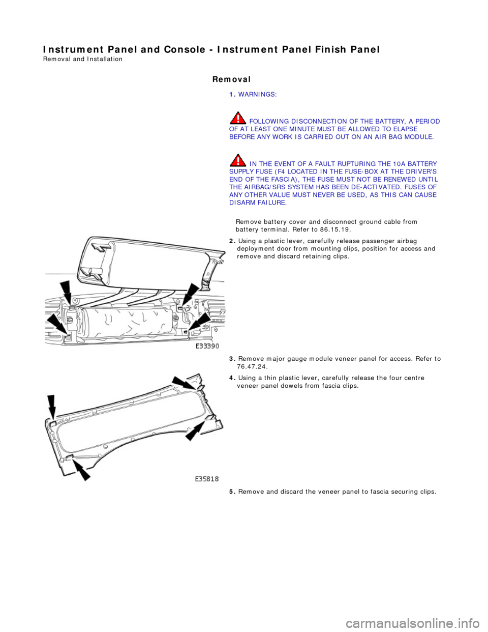
2. Using a plastic lever, carefu lly release passenger airbag
deployment door from mounting cl ips, position for access and
remove and discard retaining clips.
3. Remove major gauge module veneer panel for access. Refer to
76.47.24.
4. Using a thin plastic lever, care fully release the four centre
veneer panel dowels from fascia clips.
5. Remove and discard the veneer pa nel to fascia securing clips.
Page 2275 of 2490
Handles, Locks, Latches and Entry Systems - Door Lock Control Switch
Removal and Installation
Removal
1. Disconnect battery ground cable; refer to 86.15.19.
2. Remove center console veneer panel; refer to 76.47.26.
3. Displace radio for access; refer to 86.50.03.
4. Disconnect air conditioning control module flying lead
connector (blue) from harness connector located at side of 'J'
gate.
5. Displace air conditioning switch module / center console
switch module assembly.
Remove screw.
Reposition assembly for access to connector.
6. Remove air conditioning switch module / center console switch
module assembly.
Disconnect center console switch module harness
connector.
Remove assembly.
Page 2277 of 2490
Handles, Locks, Latches and Entry Systems - Exterior Driver Door Handle
Removal and Installation
Removal
1. Motor door glass to fully up position.
2. Remove battery cover and disconnect ground cable from
battery terminal. Refer to 86.15.19.
3. Remove door casing veneer panel. Refer to 76.47.11.
4. Remove door casing for access. Refer to 76.34.01.
5. Feeding electrical harness thro ugh water shedder, carefully
peel shedder from door and pl ace adhesive face down on a
clean dry polythene sheet.
6. Position PVC inner sheet for access.
7. Disconnect outer handle link rod from lock assembly.
8. Slacken and remove outer handle rear securing bolt.
9. Slacken and remove security gu ard lower securing bolt and
remove guard from door.
Page 2278 of 2490
10. Pull door barrel to lock link rod locking collar downward to
release link rod.
11. Holding handle firmly in posi tion, slacken and remove front
securing bolt and remove ha ndle assembly from door.
12. Remove door handle clamping plate.
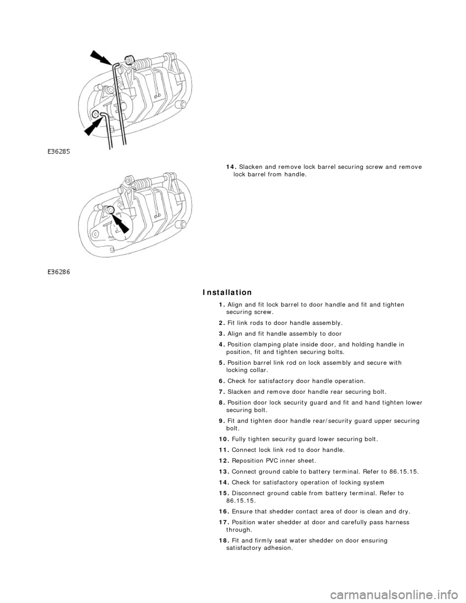
13. Remove link rods from door handle assembly.
Page 2279 of 2490

Installation
14. Slacken and remove lock barre l securing screw and remove
lock barrel from handle.
1. Align and fit lock barrel to door handle and fit and tighten
securing screw.
2. Fit link rods to door handle assembly.
3. Align and fit handle assembly to door
4. Position clamping plate inside door, and holding handle in
position, fit and tighten securing bolts.
5. Position barrel link rod on lock assembly and secure with
locking collar.
6. Check for satisfactory door handle operation.
7. Slacken and remove door handle rear securing bolt.
8. Position door lock security guard and fit and hand tighten lower
securing bolt.
9. Fit and tighten door handle rear /security guard upper securing
bolt.
10. Fully tighten security guard lower securing bolt.
11. Connect lock link rod to door handle.
12. Reposition PVC inner sheet.
13. Connect ground cable to battery terminal. Refer to 86.15.15.
14. Check for satisfactory operation of locking system
15. Disconnect ground cable from battery terminal. Refer to
86.15.15.
16. Ensure that shedder contact area of door is clean and dry.
17. Position water shedder at door and carefully pass harness
through.
18. Fit and firmly seat water shedder on door ensuring
satisfactory adhesion.